Page 3091 of 5135

ON±VEHICLE INSPECTION
1. WINDSHIELD WASHER MOTOR AND PUMP ASSY
(a) Operation Che")
660CL±01
E67356
E67356
E67352
E68115
66±4
± WIPER & WASHERWIPER AND WASHER SYSTEM
AVENSIS REPAIR MANUAL (RM1018E)
ON±VEHICLE INSPECTION
1. WINDSHIELD WASHER MOTOR AND PUMP ASSY
(a) Operation Check
(1) Pour the washer fluid into the washer jar with the
washer motor and the pump installed to the washer
jar assy.
(2) Connect the battery (+) to the terminal 1 of the wind-
shield washer motor and pump assy, the battery (±)
to the terminal 2 of the windshield washer motor and
pump assy. Check that the washer fluid comes out
from the washer jar.
2. REAR WASHER MOTOR ASSY
(a) Operation Check
(1) Pour the washer fluid into the washer jar with the
washer motor and the pump installed to the washer
jar assy.
(2) Connect the battery (+) to the terminal 1 of the rear
washer motor assy, the battery (±) to the terminal 2
of the rear washer motor assy. Check that the wash-
er fluid comes out from the washer jar.
3. HEADLAMP CLEANER MOTOR AND PUMP ASSY
(a) Operation Check
(1) Pour the washer fluid into the washer jar with the
washer motor and the pump installed to the washer
jar assy.
(2) Connect the battery (+) to the terminal 2 of the head-
lamp cleaner motor and pump assy, the battery (±)
to the terminal 1 of the headlamp cleaner motor and
pump assy. Check that the washer fluid comes out
from the washer jar.
4. RAIN SENSOR
(a) Check voltage of each terminal of the connector
Standard:
Tester connectionConditionSpecified voltage
2 ± 3Rain sensor is covered by
handSignal waveform
Page 3092 of 5135

5. WINDSHIELD WIPER RELAY ASSY
(a) Check voltage of each terminal of the connector
Standard:
Tester connectionCo")
E68116
± WIPER & WASHERWIPER AND WASHER SYSTEM
66±5
AVENSIS REPAIR MANUAL (RM1018E)
5. WINDSHIELD WIPER RELAY ASSY
(a) Check voltage of each terminal of the connector
Standard:
Tester connectionConditionSpecified voltage
1 (+B) ± Body groundIgnition switch OFF � ON0 � 10 to 14 V
2 (RSI) ± Body groundRain sensor is covered by handSignal waveform
4 (WF) ± Body groundFront washer switch OFF � ON10 to 14 V � 0 V
8 (+2) ± Body groundFront wiper is in high speed operation
(When front wiper switch is in AUTO position)10 to 14 V
9 (F1) ± Body groundFront wiper switch OFF � AUTO10 to 14 V � 0 V
11 (F2) ± Body groundFront wiper switch OFF � AUTO0 � 10 to 14 V
12 (WF) ± Body groundFront washer switch OFF� ON10 to 14 V � 0 V
16 (+1) ± Body groundFront wiper is in 10 speed operation
(when front wiper switch is in AUTO position)10 to 14 V
17 (+S) ± Body groundAlwaysBelow 1 V
19 (SP) ± Body groundIgnition switch OFF � ON0 V � 10 to 14 V
20 (VR1) ± Body groundIgnition switch OFF � ON0 V � 10 to 14 V
22 (E) ± Body groundAlwaysBelow 1 V
23 (SG) ± Body groundAlwaysBelow 1 V
24 (VP2) ± Body groundIgnition switch is ON and rain sensor adjust
switch is in (+) position � (±) positionSignal waveform
6. AUTO WIPER SYSTEM OPERATION CHECK
(a) Spray once at the area where the rain sensor is placed, then the wiper blades immediately will carry
out a wiping cycle. If the water is continuos sprayed to the rain sensor area of the windscreen, the wiper
blades first should carry out interval mode, then change to low speed and finally reach high speed after
a few seconds.
By stopping spraying water to the screen the wiper blade changing back their speed until they stop
wiping.
Page 3093 of 5135

PROBLEM SYMPTOMS TABLE
1.FRONT WIPER AND WASHER SYSTEM (W/O AUTO WIPER SYSTEM)
SymptomSuspect AreaSee page
F")
660CK±01
66±2
±
WIPER & WASHER WIPER AND WASHER SYSTEM
AVENSIS REPAIR MANUAL (RM1018E)
PROBLEM SYMPTOMS TABLE
1.FRONT WIPER AND WASHER SYSTEM (W/O AUTO WIPER SYSTEM)
SymptomSuspect AreaSee page
Front wipers and washers do not operate.
1. IG relay
2. WIP fuse
3. Windshield wiper switch assy
4. Wire harness or connector±
±
66±6 ±
Front wipers do not operate in LO or HI.
1. Windshield wiper switch assy
2. Windshield wiper motor assy
3. Wire harness or connector66±6
66±6±
Front wipers do not operate in INT.
1. Windshield wiper switch assy
2. Windshield wiper motor assy
3. Wire harness or connector66±6
66±6±
Front washer motor does not operate.
1 Windshield washer switch assy
2. Windshield washer motor assy
3. Wire harness or connector66±6
66±6±
Front wipers does not operate when washer switch in ON.
1. Windshield wiper switch assy
2. Windshield wiper motor assy
3. Wire harness or connector66±6
66±6±
Washer fluid does not operate.Washer hose and nozzle±
� When front wiper switch is in HI position, the wiper blade is in
contact with the body.
� When the front wiper switch is OFF, the wiper blade does not
retract or the retract position is wrong.
1. Windshield wiper motor assy
2. Front wiper arm installation position66±6
66±13
2. FRONT WIPER AND WASHER SYSTEM (W/ AUTO WIPER SYSTEM)
SymptomSuspect AreaSee page
Front wipers and washer do not operate.
1. IG1 relay
2. WIP fuse
3. Windshield wiper switch assy
4. Windshield wiper relay assy
5. Wire harness or connector±
±
66±6
66±6 ±
Front wipers does not operate in LO
(Auto wiper system is normal).Windshield wiper switch assy66±6
Front wipers does not operate in HI
(Auto wiper system is normal).1. Windshield wiper switch assy
2. Wire harness or connector66±6
±
Front washer motor does not operate.
1. Windshield wiper switch assy
2. Windshield washer motor assy
3. Wire harness or connector66±6
66±6±
Auto wiper system does not operate.
1. Windshield wiper switch assy
2. Windshield wiper relay assy
3. Rain sensor
4. Wire harness or connector66±6
66±6
66±4±
Page 3097 of 5135
650T4±01
I35240
I35240
A
B
A
±
LIGHTING HEIGHT CONTROL SENSOR SUB±ASSY REAR RH
65±29
AVENSIS REPAIR MANUAL (RM1018E)
HEIGHT CONTROL SENSOR SUB±ASSY REAR RH
REPLACEMENT
1.REMOVE HEIGHT CONTROL SENSOR SUB±ASSY
REAR RH
(a)Disconnect the connector.
(b)Remove the 2 bolts, the nut and height control sensor sub±assy rear RH.
2.INSTALL HEIGHT CONTROL SENSOR SUB±ASSY REAR RH
(a)Install the height control sensor sub±assy rear RH with the 2 bolts and the nut.
Torque:
Bolt (A): 7.9 N �m (81 kgf �cm, 70 in. �lbf)
Nut (B): 5.8 N �m (59 kgf �cm, 51 in. �lbf)
(b)Connect the connector.
3.HEADLIGHT AIM ONLY (See page 65±19)
Page 3098 of 5135
650T3±01
I35231
I35231
AB
A
65±28
±
LIGHTING HEIGHT CONTROL SENSOR SUB±ASSY FR RH
AVENSIS REPAIR MANUAL (RM1018E)
HEIGHT CONTROL SENSOR SUB±ASSY FR RH
REPLACEMENT
1.REMOVE HEIGHT CONTROL SENSOR SUB±ASSY FR RH
(a)Disconnect the connector.
(b)Remove the 3 nuts and height control sensor sub±assy front RH.
2.INSTALL HEIGHT CONTROL SENSOR SUB±ASSY FR RH
(a)Install the height control sensor sub±assy front RH with the 3 nuts.
Torque:
A: 7.9 N �m (81 kgf �cm, 70 in. �lbf)
B: 5.8 N �m (59 kgf �cm, 51 in. �lbf)
(b)Connect the connector.
3.HEADLIGHT AIM ONLY (See page 65±19)
Page 3117 of 5135
E68134
20��6�
0� +45�
±45�(Low) (High)
E68135
21.3��6� 0�
+45� ±45�(Low)
(High)
65±14
± LIGHTINGLIGHTING SYSTEM
AVENSIS REPAIR MANUAL (RM1018E)
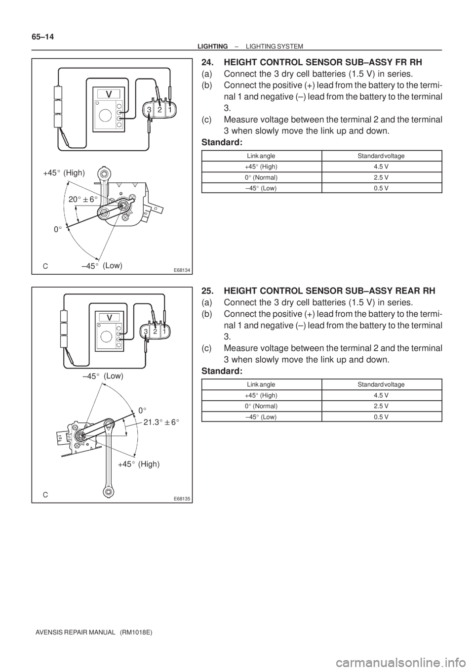
24. HEIGHT CONTROL SENSOR SUB±ASSY FR RH
(a) Connect the 3 dry cell batteries (1.5 V) in series.
(b) Connect the positive (+) lead from the battery to the termi-
nal 1 and negative (±) lead from the battery to the terminal
3.
(c) Measure voltage between the terminal 2 and the terminal
3 when slowly move the link up and down.
Standard:
Link angleStandard voltage
+45� (High)4.5 V
0� (Normal)2.5 V
±45� (Low)0.5 V
25. HEIGHT CONTROL SENSOR SUB±ASSY REAR RH
(a) Connect the 3 dry cell batteries (1.5 V) in series.
(b) Connect the positive (+) lead from the battery to the termi-
nal 1 and negative (±) lead from the battery to the terminal
3.
(c) Measure voltage between the terminal 2 and the terminal
3 when slowly move the link up and down.
Standard:
Link angleStandard voltage
+45� (High)4.5 V
0� (Normal)2.5 V
±45� (Low)0.5 V
Page 3125 of 5135
I35174
I35177
I35176
I351782 Clips
I35179
± AUDIO & VISUAL SYSTEMMULTI±DISPLAY (CRT DISPLAY) DISPLAY
67±7
AVENSIS REPAIR MANUAL (RM1018E)
(b) Remove the 4 screws and the instrument cluster finish
panel assy.
6. REMOVE CONTROL KNOB PROTECTOR NO.1
(a) Remove the screw and control knob protector No.1.
(b) Separate the position sensor.
7. REMOVE MULTI±DISPLAY (CRT DISPLAY) DISPLAY
(a) Remove the 4 screws and separate the navigation com-
puter cover.
(b) Disengage the 2 clips, slide them in the arrow direction
shown in the illustration to remove the navigation comput-
er cover.
(c) Slide the lock of the connector in the arrow direction
shown in the illustration to disconnect the flexible flat
cable.
Page 3127 of 5135
I35183
I35184
I35185
I35186
± AUDIO & VISUAL SYSTEMMULTI±DISPLAY (CRT DISPLAY) DISPLAY
67±9
AVENSIS REPAIR MANUAL (RM1018E)
(j) Remove the 4 screws and the multi±display.
8. INSTALL MULTI±DISPLAY (CRT DISPLAY) DISPLAY
(a) Install the multi±display with the 4 screws.
NOTICE:
Tighten each screw together with the earth wire.
(b) Insert the flexible flat cable as deep as possible and install
it by sliding the lock of the connector in the arrow direction
shown in the illustration.
9. INSTALL CONTROL KNOB PROTECTOR NO.1
(a) Fit the protrusion of the position sensor into the groove
shown in the illustration to fix.
(b) Install the control knob protector No.1.

HEIGHT CONTROL SENSOR SUB±ASSY REAR RH
REPLACEMENT
1.REMOVE HEIGHT CONTROL S")

HEIGHT CONTROL SENSOR SUB±ASSY FR RH
REPLACEMENT
1.REMOVE HEIGHT CONTROL SENSOR")
 DISPLAY
67±7
AVENSIS REPAIR MANUAL (RM1018E)
(b) Remove the 4 screws and the instrument cluster finish")
 DISPLAY
67±9
AVENSIS REPAIR MANUAL (RM1018E)
(j) Remove the 4 screws and the multi±display.
8. INSTALL MULTI±DISPL")