Page 3464 of 5135
Abbreviations Meaning
HIHigh
HIDHigh Intensity Discharge (Head Lamp)
HSGHousing
HTHard Top
HWSHeated Windshield System
ICIntegrated")
± INTRODUCTIONTERMS
01±9
1AZ±FSE ENGINE REPAIR MANUAL (RM1019E)Abbreviations Meaning
HIHigh
HIDHigh Intensity Discharge (Head Lamp)
HSGHousing
HTHard Top
HWSHeated Windshield System
ICIntegrated Circuit
IDIIndirect Diesel Injection
IFSIndependent Front Suspension
IGIgnition
IIAIntegrated Ignition Assembly
INIntake (Manifold, Valve)
INTIntermittent
I/PInstrument Panel
IRSIndependent Rear Suspension
ISCIdle Speed Control
J/BJunction Block
J/CJunction Connector
KDKick±Down
LANLocal Area Network
LBLiftback
LCDLiquid Crystal Display
LEDLight Emitting Diode
LHLeft±Hand
LHDLeft±Hand Drive
L/H/WLength, Height, Width
LLCLong±Life Coolant
LNGLiquified Natural Gas
LOLow
LPGLiquified Petroleum Gas
LSDLimited Slip Differential
LSP & PVLoad Sensing Proportioning And Bypass Valve
LSPVLoad Sensing Proportioning Valve
MAPManifold Absolute Pressure
MAX.Maximum
MICMicrophone
MILMalfunction Indicator Lamp
MIN.Minimum
MG1Motor Generator No.1
MG2Motor Generator No.2
MPMultipurpose
MPIMultipoint Electronic Injection
MPXMultiplex Communication System
M/T, MTMManual Transmission (Transaxle)
MTMount
MTGMounting
NNeutral
NANatural Aspiration
No.Number
O2SOxygen Sensor
O/DOverdrive
OEMOriginal Equipment Manufacturing
Page 3465 of 5135
Abbreviations Meaning
OHCOverhead Camshaft
OHVOverhead Valve
OPTOption
ORVROn±board Refilling Vapor Recovery
O/SOversize
P & BVPro")
01±10
± INTRODUCTIONTERMS
1AZ±FSE ENGINE REPAIR MANUAL (RM1019E)Abbreviations Meaning
OHCOverhead Camshaft
OHVOverhead Valve
OPTOption
ORVROn±board Refilling Vapor Recovery
O/SOversize
P & BVProportioning And Bypass Valve
PCSPower Control System
PCVPositive Crankcase Ventilation
PKBParking Brake
PPSProgressive Power Steering
PTCPositive Temperature Coefficient
PSPower Steering
PTOPower Take±Off
P/WPower Window
R & PRack And Pinion
RAMRandom Access Memory
R/BRelay Block
RBSRecirculating Ball Type Steering
R/FReinforcement
RFSRigid Front Suspension
RHRight±Hand
RHDRight±Hand Drive
RLYRelay
ROMRead Only Memory
RrRear
RRSRigid Rear Suspension
RWDRear±Wheel Drive
SDNSedan
SENSensor
SICSStarting Injection Control System
SOCState Of Charge
SOHCSingle Overhead Camshaft
SPECSpecification
SPISingle Point Injection
SRSSupplemental Restraint System
SSMSpecial Service Materials
SSTSpecial Service Tools
STDStandard
STJCold±Start Fuel Injection
SWSwitch
SYSSystem
T/ATransaxle
TACHTachometer
TBIThrottle Body Electronic Fuel Injection
TCTurbocharger
TCCSTOYOTA Computer±Controlled System
TCVTiming Control Valve
TDCTop Dead Center
TEMP.Temperature
TEMSTOYOTA Electronic Modulated Suspension
TFTToyota Free±Tronic
Page 3512 of 5135

GLOSSARY OF SAE AND TOYOTA TERMS
This glossary lists all SAE±J1930 terms and abbreviations u")
010BZ±02
01±6
± INTRODUCTIONTERMS FOR MANUAL TRANSAXLE REPAIR MANUAL
C250 M/T REPAIR MANUAL (RM1020E)
GLOSSARY OF SAE AND TOYOTA TERMS
This glossary lists all SAE±J1930 terms and abbreviations used in this manual in compliance with SAE rec-
ommendations, as well as their Toyota equivalents.
SAE
ABBREVIATIONSSAE TERMSTOYOTA TERMS
( )±±ABBREVIATIONS
A/CAir ConditioningAir Conditioner
ACLAir CleanerAir Cleaner
AIRSecondary Air InjectionAir Injection (AI)
APAccelerator Pedal±
B+Battery Positive Voltage+B, Battery Voltage
BAROBarometric Pressure±
CACCharge Air CoolerInter cooler
CARBCarburetorCarburetor
CFIContinuous Fuel Injection±
CKPCrankshaft PositionCrank Angle
CLClosed LoopClosed Loop
CMPCamshaft positionCam Angle
CPPClutch Pedal Position±
CTOXContinuous Trap Oxidizer±
CTPClosed Throttle Potion±
DFIDirect Fuel Injection (Diesel)Direct Injection (DI)
DIDistributor Ignition±
DLC1
DLC2
DLC3Data Link Connector 1
Data Link Connector 2
Data Link Connector 31: Check Connector
2: Total Diagnosis Communication Link (TDCL)
3: OBD II Diagnostic Connector
DTCDiagnostic Trouble CodeDiagnostic Code
DTMDiagnostic Test Mode±
ECLEngine Control Level±
ECMEngine Control ModuleEngine ECU (Electronic Control Unit)
ECTEngine Control TemperatureCoolant Temperature, Water Temperature (THW)
EEPROMElectrically Erasable Programmable Read Only
memoryElectrically Erasable Programmable Read Only memory
(EEPROM),
Erasable Programmable Read Only memory (EPROM)
EFEEarly Fuel EvaporationCold Mixture Heater (CMH), Heat Control Valve (HCV)
EGRExhaust Gas RecirculationExhaust Gas Recirculation (EGR)
EIElectronic IgnitionDistributorless Ignition (DI)
EMEngine ModificationEngine Modification (EM)
EPROMErasable Programmable Read Only MemoryProgrammable Read Only Memory (PROM)
EVAPEvaporative EmissionEvaporative Emission Control (EVAP)
FCFan Control±
FEEPROMFlash Electrically Erasable Programmable
Read Only Memory±
FEPROMFlash Erasable Programmable Read Only Memory±
FFFlexible Fuel±
FPFuel PumpFuel Pump
GENGeneratorAlternator
GNDGroundGround (GND)
HO2SHeated Oxygen SensorHeated Oxygen Sensor (HO2S)
IACIdol Air ControlIdol Speed Control (ISC)
IATIntake Air TemperatureIntake or Inlet Air Temperature
ICMIgnition Control Module±
IFIIndirect Fuel InjectionIndirect Injection
IFSInertia Fuel±Shutoff±
Page 3513 of 5135
 ISC
Idle Speed Control±
KSKnock SensorKnock Sensor
MAFMass Air FlowAir Flow Meter
MAPManifold Absolute")
± INTRODUCTIONTERMS FOR MANUAL TRANSAXLE REPAIR MANUAL
01±7
C250 M/T REPAIR MANUAL (RM1020E) ISC
Idle Speed Control±
KSKnock SensorKnock Sensor
MAFMass Air FlowAir Flow Meter
MAPManifold Absolute PressureManifold Pressure
Intake Vacuum
MCMixture Control
Electric Bleed Air Control Valve (EBCV)
Mixture Control Valve (MCV)
Electric Air Control Valve (EACV)
MDPManifold Differential Pressure±
MFIMultiport Fuel InjectionElectronic Fuel Injection (EFI)
MILMalfunction Indicator LampCheck Engine Light
MSTManifold Surface temperature±
MVZManifold Vacuum Zone±
NVRAMNon±Volatile Random Access Memory±
O2SOxygen SensorOxygen Sensor, O2 Sensor (O2S)
OBDOn±Board DiagnosticOn±Board Diagnostic (OBD)
OCOxidation Catalytic ConverterOxidation Catalyst Converter (OC), CC0
OPOpen LoopOpen Loop
PAIRPulsed Secondary Air InjectionAir Suction (AS)
PCMPowertrain Control Module±
PNPPark/Neutral Position±
PROMProgrammable Read Only Memory±
PSPPower Steering Pressure±
PTOXPeriodic Trap OxidizerDiesel Particulate Filter (DPF)
Diesel Particulate Trap (DPT)
RAMRandom Access MemoryRandom Access Memory (RAM)
RMRelay Module±
ROMRead Only MemoryRead Only Memory (ROM)
RPMEngine SpeedEngine Speed
SCSuperchargerSupercharger
SCBSupercharger Bypass±
SFISequential Multiport Fuel InjectionElectronic Fuel Injection (EFI), Sequential Injection
SPLSmoke Puff Limiter±
SRIService Reminder Indicator±
SRTSystem Readiness Test±
STScan Tool±
TBThrottle BodyThrottle Body
TBIThrottle Body Fuel InjectionSingle Point Injection
Central Fuel Injection (Ci)
TCTurbochargerTurbocharger
TCCTorque Converter ClutchTorque Converter
TCMTransmission Control ModuleTransmission ECU (Electronic Control Unit)
TPThrottle PositionThrottle Position
TRTransmission Range±
TVVThermal Vacuum ValveBimetallic Vacuum Switching Valve (BVSV)
Thermostatic Vacuum Switching Valve (TVSV)
TWCThree±Way Catalytic ConverterThree±Way Catalytic (TWC)
CC
RO
TWC+OCThree±Way + Oxidation Catalytic ConverterCCR + CCO
VA FVolume Air FlowAir Flow Meter
VRVoltage RegulatorVoltage Regulator
VSSVehicle Speed SensorVehicle Speed Sensor (Read Switch Type)
WOTWide Open ThrottleFull Throttle
Page 3637 of 5135
C83143
C83144
C83142
D03900
D03900
± AUTOMATIC TRANSMISSION / TRANSAUTOMATIC TRANSAXLE ASSY (U241E)
40±15
U241E A/T REPAIR MANUAL (RM840U)
4. REMOVE OIL COOLER TUBE UNION(INLET OIL
COOLER UNION)
(a) Remove the union.
(b) Remove the O±ring from the union.
5. REMOVE OIL COOLER TUBE UNION(OUTLET OIL
COOLER UNION)
(a) Remove the elbow.
(b) Remove the O±ring from the elbow.
6. REMOVE TRANSAXLE CASE NO.1 PLUG
(a) Remove the 4 transaxle case No. 1 plugs from the trans-
axle case.
(b) Remove 4 O±rings from the 4 transaxle case No. 1 plugs.
7. REMOVE SPEED SENSOR(TMC ±MADE)
(a) Remove the 2 bolts and the 2 speed sensors from the
transaxle assy.
(b) Remove the 2 O±rings from the sensors.
8. REMOVE TRANSMISSION REVOLUTION
SENSOR(AISIN ±MADE)
(a) Remove the 2 bolts and the 2 transmission revolution
sensors from the transaxle assy.
(b) Remove the 2 O±rings from the sensors.
Page 3638 of 5135
D09176
D09177
AT0103
D09637
40±16
± AUTOMATIC TRANSMISSION / TRANSAUTOMATIC TRANSAXLE ASSY (U241E)
U241E A/T REPAIR MANUAL (RM840U)
9. FIX AUTOMATIC TRANSAXLE ASSY
10. REMOVE AUTOMATIC TRANSAXLE OIL PAN
SUB±ASSY
(a) Remove the 18 bolts.
(b) Remove the oil pan and 2 magnets.
11. REMOVE AUTOMATIC TRANSAXLE OIL PAN GASKET
(a) Remove the gasket from the oil pan.
12. INSPECT AUTOMATIC TRANSAXLE OIL PAN
SUB±ASSY
(a) Remove the magnets and use them to collect any steel
chips. Examine the chips and particles in the pan and on
the magnet to determine what type of wear has occurred
in the transaxle:
Steel (magnetic).... bearing, gear and plate wear
Brass (non±magnetic).... bushing wear
13. REMOVE TRANSMISSION WIRE
(a) Remove the 5 connectors from the shift solenoid valves.
(b) Remove the bolt, clamp and ATF temperature sensor.
Page 3687 of 5135
D09178
D09180
D09179
± AUTOMATIC TRANSMISSION / TRANSAUTOMATIC TRANSAXLE ASSY (U241E)
40±65
U241E A/T REPAIR MANUAL (RM840U)
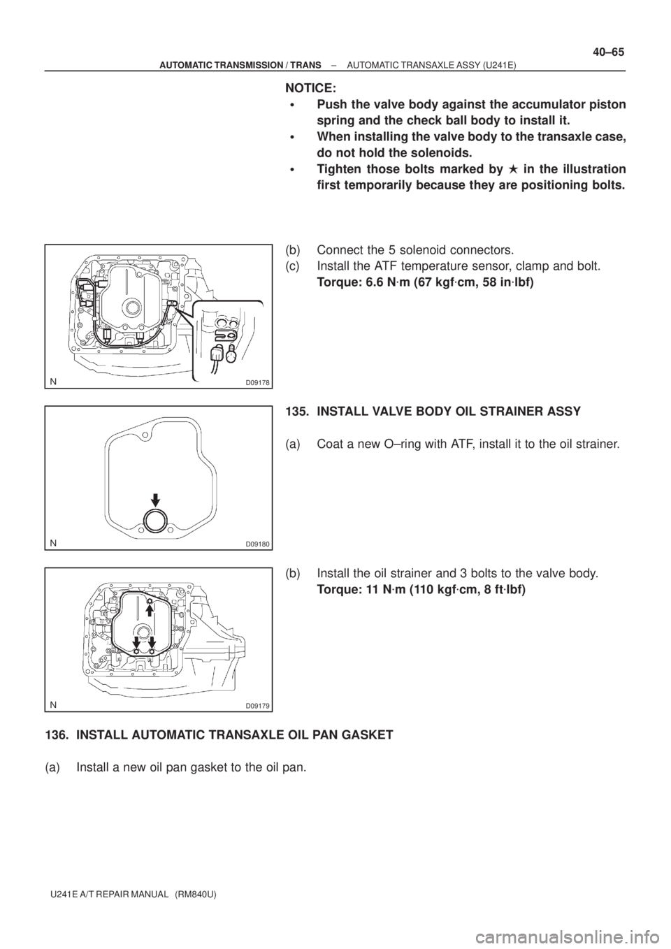
NOTICE:
�Push the valve body against the accumulator piston
spring and the check ball body to install it.
�When installing the valve body to the transaxle case,
do not hold the solenoids.
�Tighten those bolts marked by � in the illustration
first temporarily because they are positioning bolts.
(b) Connect the 5 solenoid connectors.
(c) Install the ATF temperature sensor, clamp and bolt.
Torque: 6.6 N�m (67 kgf�cm, 58 in�lbf)
135. INSTALL VALVE BODY OIL STRAINER ASSY
(a) Coat a new O±ring with ATF, install it to the oil strainer.
(b) Install the oil strainer and 3 bolts to the valve body.
Torque: 11 N�m (110 kgf�cm, 8 ft�lbf)
136. INSTALL AUTOMATIC TRANSAXLE OIL PAN GASKET
(a) Install a new oil pan gasket to the oil pan.
Page 3688 of 5135

U241E A/T REPAIR MANUAL (RM840U)
137. I N S TA L L A U TO M AT I C TRANSAXLE OIL PAN
SUB±")
D25674
D09176
D03900
D03900
C83144
40±66
± AUTOMATIC TRANSMISSION / TRANSAUTOMATIC TRANSAXLE ASSY (U241E)
U241E A/T REPAIR MANUAL (RM840U)
137. I N S TA L L A U TO M AT I C TRANSAXLE OIL PAN
SUB±ASSY
(a) Install the 2 magnets in the oil pan.
(b) Apply seal packing or equivalent to new 18 bolts.
Seal packing:
THREE BOND 2430 or equivalent
(c) Install oil pan and 18 bolts to the transaxle case.
Torque: 7.8 N�m (80 kgf�cm, 69 in.�lbf)
NOTICE:
Because the bolts should be seal bolts, apply seal packing
to new bolts and tighten them within 10 minutes after ap-
plication.
138. INSTALL SPEED SENSOR(TMC ±MADE)
(a) Coat 2 new O±rings with ATF, install them to the 2 sen-
sors.
(b) Install the 2 sensors with the 2 bolts to the transaxle case.
Torque: 11.3 N�m (115 kgf�cm, 8 ft�lbf)
139. I N S TA L L TRANSMISSION REVOLUTION
SENSOR(AISIN ±MADE)
(a) Coat 2 new O±rings with ATF, install them to the 2 sen-
sors.
(b) Install the 2 sensors with the 2 bolts to the transaxle case.
Torque: 11.3 N�m (115 kgf�cm, 8 ft�lbf)
140. INSTALL OIL COOLER TUBE UNION
(a) Coat a new O±ring with ATF, install it to the elbow.
(b) Install the elbow to the transaxle case.
Torque: 27 N�m (276 kgf�cm, 20 ft�lbf)

40±15
U241E A/T REPAIR MANUAL (RM840U)
4. REMOVE OIL COOLER TUBE UNION(INLET OIL
COOLER UNION)
(")

U241E A/T REPAIR MANUAL (RM840U)
9. FIX AUTOMATIC TRANSAXLE ASSY
10. REMOVE AUTOMATIC TRANSAXLE O")