Page 2793 of 5135
D30484
D30483
A
A
A
A
B
D11561
(a)
(c)
(b)(a)
G24210
±
MANUAL TRANSMISSION/TRANSAXLE MANUAL TRANSAXLE ASSY (1ZZ±FE/3ZZ±FE)
41±19
AVENSIS REPAIR MANUAL (RM1018E)
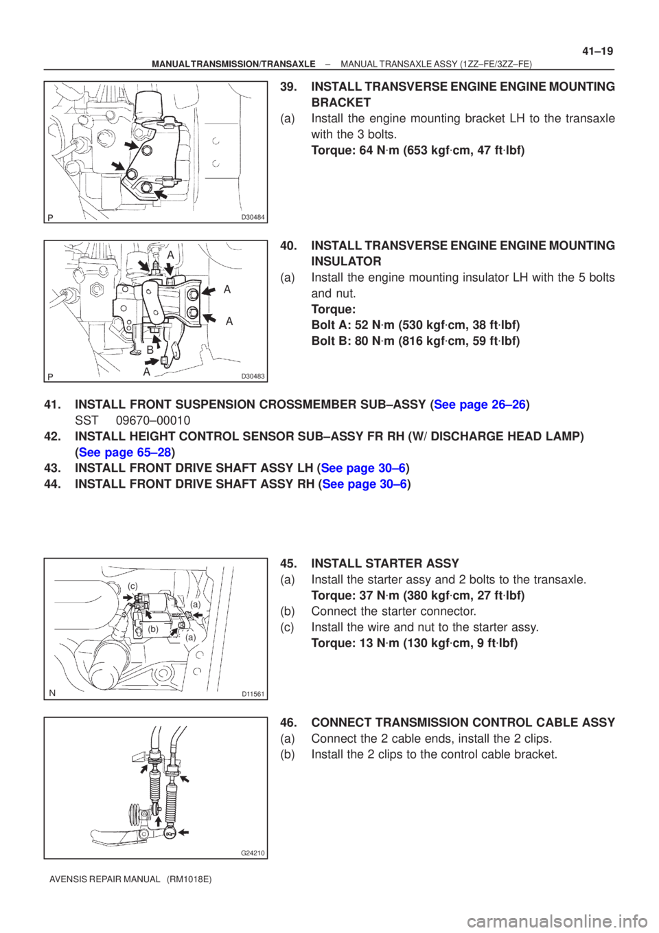
39. INSTALL TRANSVERSE ENGINE ENGINE MOUNTING
BRACKET
(a) Install the engine mounting bracket LH to the transaxle
with the 3 bolts.
Torque: 64 N �m (653 kgf �cm, 47 ft �lbf)
40. INSTALL TRANSVERSE ENGINE ENGINE MOUNTING INSULATOR
(a) Install the engine mounting insulator LH with the 5 bolts and nut.
Torque:
Bolt A: 52 N �m (530 kgf �cm, 38 ft �lbf)
Bolt B: 80 N �m (816 kgf �cm, 59 ft �lbf)
41.INSTALL FRONT SUSPENSION CROSSMEMBER SUB±ASSY (See page 26±26) SST 09670±00010
42. INSTALL HEIGHT CONTROL SENSOR SUB±ASSY FR RH (W/ DISCHARGE HEAD LAMP) (See page 65±28)
43.INSTALL FRONT DRIVE SHAFT ASSY LH (See page 30±6)
44.INSTALL FRONT DRIVE SHAFT ASSY RH (See page 30±6)
45. INSTALL STARTER ASSY
(a) Install the starter assy and 2 bolts to the transaxle.Torque: 37 N �m (380 kgf �cm, 27 ft �lbf)
(b) Connect the starter connector.
(c) Install the wire and nut to the starter assy.
Torque: 13 N �m (130 kgf �cm, 9 ft �lbf)
46. CONNECT TRANSMISSION CONTROL CABLE ASSY
(a) Connect the 2 cable ends, install the 2 clips.
(b) Install the 2 clips to the control cable bracket.
Page 2795 of 5135
D30480
±
MANUAL TRANSMISSION/TRANSAXLE MANUAL TRANSAXLE ASSY (1ZZ±FE/3ZZ±FE)
41±21
AVENSIS REPAIR MANUAL (RM1018E)
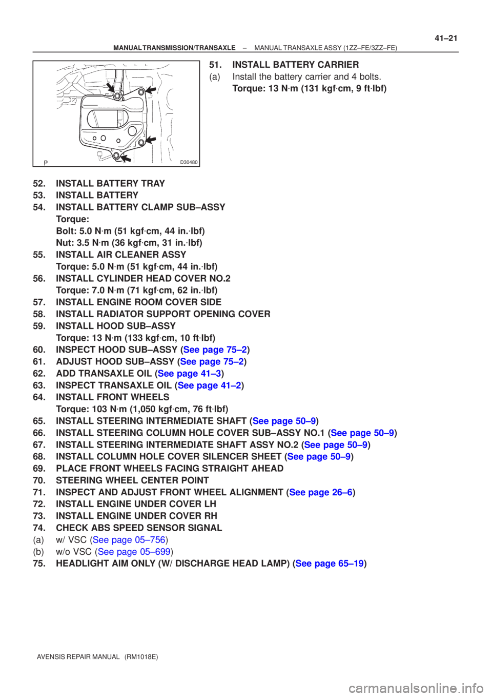
51. INSTALL BATTERY CARRIER
(a) Install the battery carrier and 4 bolts.
Torque: 13 N �m (131 kgf �cm, 9 ft �lbf)
52. INSTALL BATTERY TRAY
53. INSTALL BATTERY
54. INSTALL BATTERY CLAMP SUB±ASSY Torque:
Bolt: 5.0 N �m (51 kgf �cm, 44 in. �lbf)
Nut: 3.5 N �m (36 kgf �cm, 31 in. �lbf)
55. INSTALL AIR CLEANER ASSY Torque: 5.0 N �m (51 kgf �cm, 44 in. �lbf)
56. INSTALL CYLINDER HEAD COVER NO.2 Torque: 7.0 N �m (71 kgf �cm, 62 in. �lbf)
57. INSTALL ENGINE ROOM COVER SIDE
58. INSTALL RADIATOR SUPPORT OPENING COVER
59. INSTALL HOOD SUB±ASSY Torque: 13 N �m (133 kgf �cm, 10 ft �lbf)
60.INSPECT HOOD SUB±ASSY (See page 75±2)
61.ADJUST HOOD SUB±ASSY (See page 75±2)
62.ADD TRANSAXLE OIL (See page 41±3)
63.INSPECT TRANSAXLE OIL (See page 41±2)
64. INSTALL FRONT WHEELS
Torque: 103 N �m (1,050 kgf �cm, 76 ft �lbf)
65.INSTALL STEERING INTERMEDIATE SHAFT (See page 50±9)
66.INSTALL STEERING COLUMN HOLE COVER SUB±ASSY NO.1 (See page 50±9)
67.INSTALL STEERING INTERMEDIATE SHAFT ASSY NO.2 (See page 50±9)
68.INSTALL COLUMN HOLE COVER SILENCER SHEET (See page 50±9)
69. PLACE FRONT WHEELS FACING STRAIGHT AHEAD
70. STEERING WHEEL CENTER POINT
71.INSPECT AND ADJUST FRONT WHEEL ALIGNMENT (See page 26±6)
72. INSTALL ENGINE UNDER COVER LH
73. INSTALL ENGINE UNDER COVER RH
74. CHECK ABS SPEED SENSOR SIGNAL
(a)w/ VSC (See page 05±756)
(b)w/o VSC (See page 05±699)
75.HEADLIGHT AIM ONLY (W/ DISCHARGE HEAD LAMP) (See page 65±19)
Page 2801 of 5135
5006Z±01
50±20
±
STEERING COLUMN POWER STEERING ECU ASSY
AVENSIS REPAIR MANUAL (RM1018E)
POWER STEERING ECU ASSY
REPLACEMENT
1.PRECAUTION (See page 60±1)
2.DISCONNECT BATTERY NEGATIVE TERMINAL (See page 60±1)
3.REMOVE INSTRUMENT CLUSTER FINISH PANEL GARNISH NO.1 (See page 71±11)
4.REMOVE INSTRUMENT CLUSTER FINISH PANEL GARNISH NO.2 (See page 71±11)
5.REMOVE INSTRUMENT PANEL REGISTER ASSY CTR (See page 71±11)
6.REMOVE STEERING COLUMN COVER LWR (See page 50±9)
7. REMOVE STEERING COLUMN COVER W/INSTRUMENT CLUSTER FINISH PANEL ASSY (See page 50±9)
8.REMOVE COMBINATION METER ASSY (See page 71±11)
9.REMOVE INSTRUMENT PANEL REGISTER ASSY NO.1 (See page 71±11)
10.REMOVE INSTRUMENT PANEL REGISTER ASSY NO.2(See page 71±11)
11.REMOVE GLOVE COMPARTMENT DOOR ASSY (See page 71±11)
12.REMOVE FRONT PILLAR GARNISH LH (See page 71±11)
13.REMOVE FRONT PILLAR GARNISH RH (See page 71±11)
14.DISCONNECT PASSENGER AIRBAG CONNECTOR(See page 71±11)
15. REMOVE INSTRUMENT PANEL SUB±ASSY UPPER W/INSTR PNL PASS L/DOOR AIR BAG
ASSY (See page 71±11)
16. REMOVE POWER STEERING ECU ASSY
NOTICE:
Thoroughly check the procedures for removing and instal-
ling the power steering ECU assy when replacing it. Do the
same for the removing and installing the steering column
assy.
(a) Mark the clamp position on the torque sensor wire har-ness in order to reinstall the wire harness as shown in the
illustration.
(b) Disconnect the torque sensor wire harness from the clamp.
NOTICE:
In case the clamp will be reused, pay attention so as not to
damage it.
(c) Disconnect the 4 connectors.
(d) LHD: (1) Remove the 2 bolts,screw and power steering ECUassy.
(e) RHD: (1) Remove the 2 bolts,2 screw and power steeringECU assy.
Page 2802 of 5135
F44857F44857
LHD:RHD:
Torque Sensor Wire Harness Clamp
Marks
Power Steering ECU Assy
Front
Motor Wire Harness
Torque Sensor
Wire Harness
Front
Torque Sensor
Wire Harness
Motor Wire Harness
Power Steering ECU Assy
Torque Sensor Wire Harness Clamp
Marks
Bolt (A)
Bolt (B)
ScrewScrew Bolt (B)Bolt (A)
± STEERING COLUMNPOWER STEERING ECU ASSY
50±21
AVENSIS REPAIR MANUAL (RM1018E)
17. INSTALL POWER STEERING ECU ASSY
(a) LHD:
Install the power steering ECU assy with the 2 bolts and
screw.
Torque:
BOLT (A): 8.0 N�m (82 kgf�cm, 71 in.�lbf)
BOLT (B): 15.5 N�m (158 kgf�cm, 11 ft�lbf)
(b) RHD:
Install the power steering ECU assy with the 2 bolts and
2 screws.
Torque:
BOLT (A): 8.0 N�m (82 kgf�cm, 71 in.�lbf)
BOLT (B): 15.5 N�m (158 kgf�cm, 11 ft�lbf)
(c) Connect the 4 connectors.
(d) Align the marks on the torque sensor wire harness with
the clamp, as shown in the illustration.
Page 2803 of 5135
50±22
±
STEERING COLUMN POWER STEERING ECU ASSY
AVENSIS REPAIR MANUAL (RM1018E)
NOTICE:
�When reusing the clamp, check that there is no dam-
age on it.
�When reinstalling the wire harness, make sure there
is no twist in the harness or with other wire harness.
18. CONNECT BATTERY NEGATIVE TERMINAL
19.INSPECT SRS WARNING LIGHT (See page 05±1184)
20.PERFORM CALIBRATION OF TORQUE SENSOR ZERO POINT (See page 05±1045)
Page 2807 of 5135
F44857F44857
LHD:RHD:
Torque Sensor Wire Harness Clamp
Marks
Power Steering ECU Assy
Front
Motor Wire Harness
Torque Sensor
Wire Harness
Front
Torque Sensor
Wire Harness
Motor Wire Harness
Power Steering ECU Assy
Torque Sensor Wire Harness Clamp
Marks 50±12
± STEERING COLUMNSTEERING COLUMN ASSY
AVENSIS REPAIR MANUAL (RM1018E)
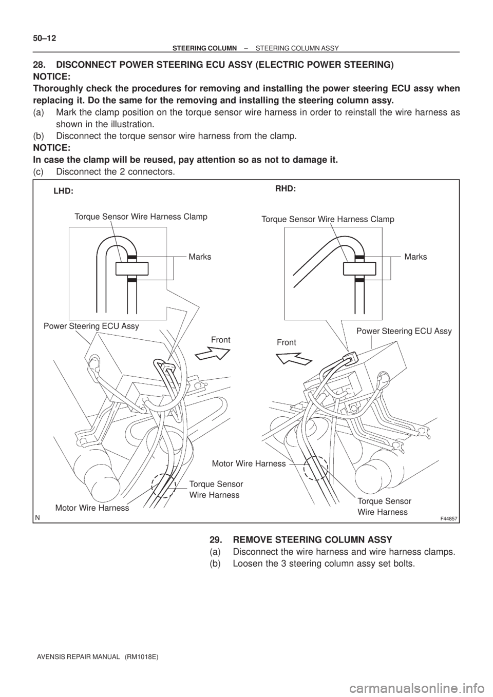
28. DISCONNECT POWER STEERING ECU ASSY (ELECTRIC POWER STEERING)
NOTICE:
Thoroughly check the procedures for removing and installing the power steering ECU assy when
replacing it. Do the same for the removing and installing the steering column assy.
(a) Mark the clamp position on the torque sensor wire harness in order to reinstall the wire harness as
shown in the illustration.
(b) Disconnect the torque sensor wire harness from the clamp.
NOTICE:
In case the clamp will be reused, pay attention so as not to damage it.
(c) Disconnect the 2 connectors.
29. REMOVE STEERING COLUMN ASSY
(a) Disconnect the wire harness and wire harness clamps.
(b) Loosen the 3 steering column assy set bolts.
Page 2808 of 5135
F44789
RHD:
A
B
Matchmarks
F44790
LHD:
Matchmarks
BA
F45269
F44793Matchmarks
±
STEERING COLUMN STEERING COLUMN ASSY
50±13
AVENSIS REPAIR MANUAL (RM1018E)
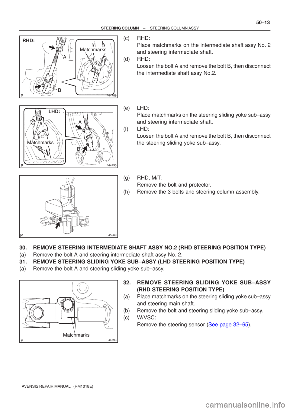
(c) RHD:
Place matchmarks on the intermediate shaft assy No. 2
and steering intermediate shaft.
(d) RHD: Loosen the bolt A and remove the bolt B, then disconnect
the intermediate shaft assy No.2.
(e) LHD: Place matchmarks on the steering sliding yoke sub±assy
and steering intermediate shaft.
(f) LHD: Loosen the bolt A and remove the bolt B, then disconnect
the steering sliding yoke sub±assy.
(g) RHD, M/T: Remove the bolt and protector.
(h) Remove the 3 bolts and steering column assembly.
30. REMOVE STEERING INTERMEDIATE SHAFT ASSY NO.2 (RHD STEERING POSITION TYPE)
(a) Remove the bolt A and steering intermediate shaft assy No. 2.
31. REMOVE STEERING SLIDING YOKE SUB±ASSY (LHD STEERING POSITION TYPE)
(a) Remove the bolt A and steering sliding yoke sub±assy. 32. REMOVE STEERING SLIDING YOKE SUB±ASSY(RHD STEERING POSITION TYPE)
(a) Place matchmarks on the steering sliding yoke sub±assy
and steering main shaft.
(b) Remove the bolt and steering sliding yoke sub±assy.
(c) W/VSC: Remove the steering sensor (See page 32±65).
Page 2809 of 5135
F44793Matchmarks
F44794
Screw
Extractor
F44795
SST
F44796
F44797
50±14
±
STEERING COLUMN STEERING COLUMN ASSY
AVENSIS REPAIR MANUAL (RM1018E)
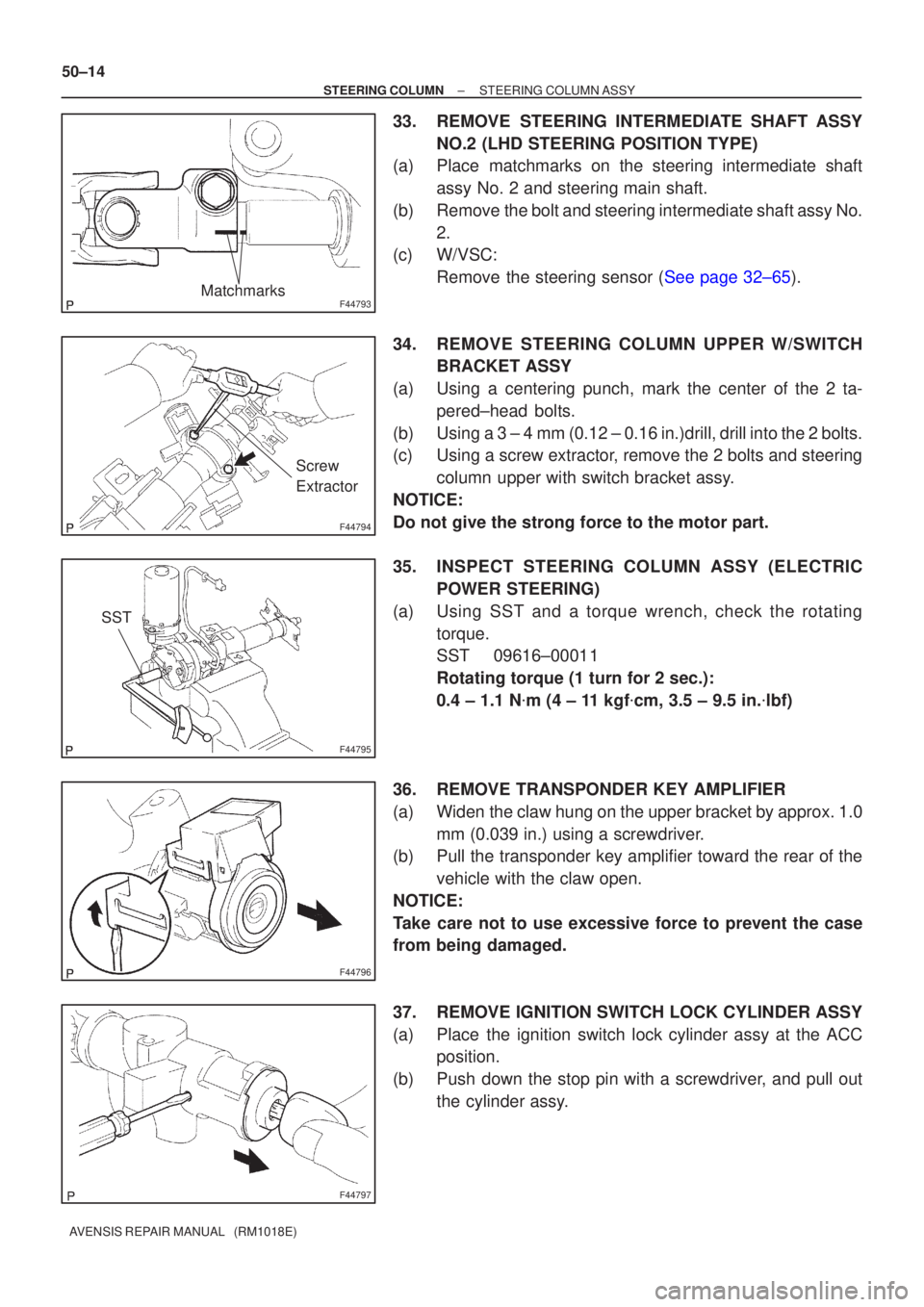
33. REMOVE STEERING INTERMEDIATE SHAFT ASSY NO.2 (LHD STEERING POSITION TYPE)
(a) Place matchmarks on the steering intermediate shaft
assy No. 2 and steering main shaft.
(b) Remove the bolt and steering intermediate shaft assy No. 2.
(c) W/VSC:
Remove the steering sensor (See page 32±65).
34. REMOVE STEERING COLUMN UPPER W/SWITCH BRACKET ASSY
(a) Using a centering punch, mark the center of the 2 ta- pered±head bolts.
(b) Using a 3 ± 4 mm (0.12 ± 0.16 in.)drill, drill into the 2 bolts.
(c) Using a screw extractor, remove the 2 bolts and steering column upper with switch bracket assy.
NOTICE:
Do not give the strong force to the motor part.
35. INSPECT STEERING COLUMN ASSY (ELECTRIC POWER STEERING)
(a) Using SST and a torque wrench, check the rotating torque.
SST 09616±00011
Rotating torque (1 turn for 2 sec.):
0.4 ± 1.1 N �m (4 ± 11 kgf �cm, 3.5 ± 9.5 in. �lbf)
36. REMOVE TRANSPONDER KEY AMPLIFIER
(a) Widen the claw hung on the upper bracket by approx. 1.0 mm (0.039 in.) using a screwdriver.
(b) Pull the transponder key amplifier toward the rear of the
vehicle with the claw open.
NOTICE:
Take care not to use excessive force to prevent the case
from being damaged.
37. REMOVE IGNITION SWITCH LOCK CYLINDER ASSY
(a) Place the ignition switch lock cylinder assy at the ACC position.
(b) Push down the stop pin with a screwdriver, and pull out the cylinder assy.