2005 NISSAN NAVARA control unit
[x] Cancel search: control unitPage 580 of 3171
BCS-14
BCM (BODY CONTROL MODULE)
CONSULT-II Function (BCM)
EKS00PA4
CONSULT-II can display each diagnostic item using the diagnostic test modes shown following.
CONSULT–II INSPECTION PROCEDURE
CAUTION:
If CONSULT-II is used with no connection of CONSULT-II CONVERTER, malfunctions might be
detected in self-diagnosis depending on control unit which carry out CAN communication.
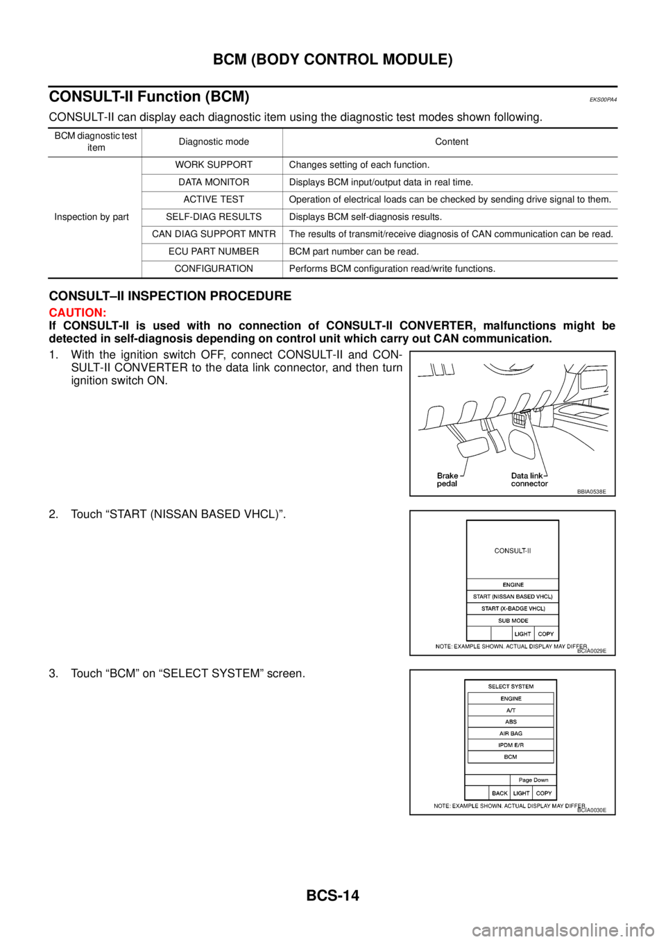
1. With the ignition switch OFF, connect CONSULT-II and CON-
SULT-II CONVERTER to the data link connector, and then turn
ignition switch ON.
2. Touch “START (NISSAN BASED VHCL)”.
3. Touch “BCM” on “SELECT SYSTEM” screen.
BCM diagnostic test
itemDiagnostic mode Content
Inspection by partWORK SUPPORT Changes setting of each function.
DATA MONITOR Displays BCM input/output data in real time.
ACTIVE TEST Operation of electrical loads can be checked by sending drive signal to them.
SELF-DIAG RESULTS Displays BCM self-diagnosis results.
CAN DIAG SUPPORT MNTR The results of transmit/receive diagnosis of CAN communication can be read.
ECU PART NUMBER BCM part number can be read.
CONFIGURATION Performs BCM configuration read/write functions.
BBIA0538E
BCIA0029E
BCIA0030E
Page 582 of 3171
BCS-16
BCM (BODY CONTROL MODULE)
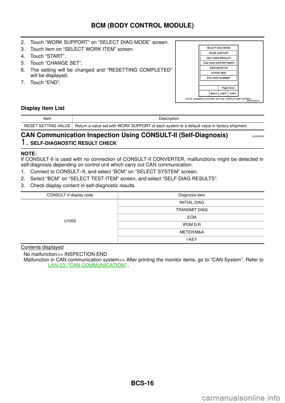
2. Touch “WORK SUPPORT” on “SELECT DIAG MODE” screen.
3. Touch item on “SELECT WORK ITEM” screen.
4. Touch “START”.
5. Touch “CHANGE SET”.
6. The setting will be changed and “RESETTING COMPLETED”
will be displayed.
7. Touch “END”.
Display Item List
CAN Communication Inspection Using CONSULT-II (Self-Diagnosis)EKS00PA5
1.SELF-DIAGNOSTIC RESULT CHECK
NOTE:
If CONSULT-II is used with no connection of CONSULT-II CONVERTER, malfunctions might be detected in
self-diagnosis depending on control unit which carry out CAN communication.
1. Connect to CONSULT–II, and select “BCM” on “SELECT SYSTEM” screen.
2. Select “BCM” on “SELECT TEST ITEM” screen, and select “SELF-DIAG RESULTS”.
3. Check display content in self-diagnostic results.
Contents displayed
No malfunction>> INSPECTION END
Malfunction in CAN communication system>> After printing the monitor items, go to “CAN System”. Refer to
LAN-23, "
CAN COMMUNICATION".
BCIA0031E
Item Description
RESET SETTING VALUE Return a value set with WORK SUPPORT of each system to a default value in factory shipment.
CONSULT-II display code Diagnosis item
U1000INITIAL DIAG
TRANSMIT DIAG
ECM
IPDM E/R
METER/M&A
I-KEY
Page 585 of 3171
BL-1
BODY, LOCK & SECURITY SYSTEM
IBODY
CONTENTS
C
D
E
F
G
H
J
K
L
M
SECTIONBL
A
B
BL
BODY, LOCK & SECURITY SYSTEM
PRECAUTIONS .......................................................... 4
Precautions for Supplemental Restraint System
(SRS)“AIRBAG”and“SEATBELTPRE-TEN-
SIONER” .................................................................. 4
Precautions for procedures with out cowl top cover..... 4
Precautions for Work ................................................ 4
Wiring Diagrams and Trouble Diagnosis .................. 4
PREPARATION ........................................................... 5
Commercial Service Tools ........................................ 5
SQUEAK AND RATTLE TROUBLE DIAGNOSES..... 6
Work Flow ................................................................ 6
CUSTOMER INTERVIEW ..................................... 6
DUPLICATE THE NOISE AND TEST DRIVE ....... 7
CHECK RELATED SERVICE BULLETINS ........... 7
LOCATE THE NOISE AND IDENTIFY THE
ROOT CAUSE ...................................................... 7
REPAIR THE CAUSE ........................................... 7
CONFIRM THE REPAIR ....................................... 8
Generic Squeak and Rattle Troubleshooting ........... 8
INSTRUMENT PANEL .......................................... 8
CENTER CONSOLE ............................................. 8
DOORS ................................................................. 8
TRUNK .................................................................. 9
SUNROOF/HEADLINING ..................................... 9
SEATS ................................................................... 9
UNDERHOOD ....................................................... 9
Diagnostic Worksheet ............................................ 10
HOOD ....................................................................... 12
Fitting Adjustment .................................................. 12
LONGITUDINAL AND LATERAL CLEARANCE
ADJUSTMENT .................................................... 13
FRONT END HEIGHT ADJUSTMENT ............... 13
SURFACE HEIGHT ADJUSTMENT ................... 13
Removal and Installation of Hood Assembly .......... 14
REMOVAL ........................................................... 14
INSTALLATION ................................................... 14
Removal and Installation of Hood Hinge ................ 15
REMOVAL ........................................................... 15
INSTALLATION ................................................... 15
Removal and Installation of Hood Lock Control ..... 15REMOVAL ........................................................... 15
INSTALLATION ................................................... 16
Hood Lock Control Inspection ................................ 17
RADIATOR CORE SUPPORT .................................. 18
Removal and Installation ........................................ 18
REMOVAL ........................................................... 18
INSTALLATION ................................................... 19
FRONT FENDER ...................................................... 20
Removal and Installation ........................................ 20
REMOVAL ........................................................... 20
INSTALLATION ................................................... 20
POWER DOOR LOCK SYSTEM .............................. 21
Component Parts and Harness Connector Location... 21
KING CAB ........................................................... 21
DOUBLE CAB ..................................................... 22
System Description ................................................. 23
OUTLINE ............................................................. 24
CAN Communication System Description .............. 25
CAN Communication Unit ....................................... 25
Schematic ............................................................... 26
Wiring Diagram —D/LOCK— ................................. 27
Terminals and Reference Value for BCM ............... 34
CONSULT-II Function (BCM) ................................. 35
CONSULT-II BASIC OPERATION PROCEDURE
... 35
CONSULT-II APPLICATION ITEMS .................... 36
Work Flow ............................................................... 37
Trouble Diagnoses Chart by Symptom ................... 37
Check Power Supply and Ground Circuit ............... 37
Check Door Switch ................................................. 39
CHECK DOOR SWITCH (DOUBLE CAB) .......... 39
CHECK DOOR SWITCH (KING CAB) ................ 41
Check Key Switch ................................................... 43
Check Door Key Cylinder Switch (LHD Model Only)... 45
Check Front Door Lock Actuator (Driver Side) ....... 48
Check Front Door Lock Actuator (Passenger Side)... 49
Check Front Door Lock Actuator Switch ................. 50
Check Rear Door Lock Actuator LH (Double Cab
Model) ..................................................................... 50
Check Rear Door Lock Actuator RH (Double Cab
Page 586 of 3171

BL-2
Model) ..................................................................... 51
Check RH and LH Rear Door Lock Actuator Switch... 51
Check Door Lock/Unlock Switch ............................ 52
Check Door Lock/Unlock Switch Indicator .............. 53
POWER DOOR LOCK — SUPER LOCK — ............ 55
Component Parts and Harness Connector Location... 55
KING CAB ........................................................... 55
DOUBLE CAB ..................................................... 56
System Description ................................................. 57
OUTLINE ............................................................. 58
OPERATION ........................................................ 58
CAN Communication System Description .............. 59
CAN Communication Unit ....................................... 59
Schematic ............................................................... 60
Wiring Diagram —D/LOCK— ................................. 61
Terminals and Reference Value for BCM ................ 69
CONSULT-II Function (BCM) .................................. 70
CONSULT-II BASIC OPERATION PROCEDURE
... 70
CONSULT-II APPLICATION ITEMS .................... 71
Work Flow ............................................................... 72
Trouble Diagnoses Chart by Symptom ................... 72
Check Power Supply and Ground Circuit ............... 73
Check Door Switch ................................................. 74
CHECK DOOR SWITCH (DOUBLE CAB) .......... 74
CHECK DOOR SWITCH (KING CAB) ................ 76
Check Key Switch ................................................... 78
Check Front Door Lock Actuator (Driver Side) ....... 80
Check Front Door Lock Actuator (Passenger Side)... 81
Check Front Door Lock Actuator Switch ................. 81
Check Rear Door Lock Actuator LH (Double Cab
Models) ................................................................... 82
Check Rear Door Lock Actuator RH (Double Cab
Models) ................................................................... 82
Check RH and LH Rear Door Lock Actuator Switch
(Double Cab Models) .............................................. 83
Check Super Lock Actuator (Driver Side) ............... 83
Check Super Lock Actuator (Passenger Side) ....... 84
Check Super Lock Actuator (Rear LH) ................... 84
Check Super Lock Actuator (Rear RH) .................. 85
Check Door Lock/Unlock Switch ............................ 86
Check Door Lock/Unlock Switch Indicator .............. 87
MULTI-REMOTE CONTROL SYSTEM ..................... 89
Component Parts and Harness Connector Location... 89
KING CAB ........................................................... 89
DOUBLE CAB ..................................................... 90
System Description ................................................. 91
INPUTS ............................................................... 91
OPERATING PROCEDURE ................................ 91
CAN Communication System Description .............. 92
Wiring Diagram — MULTI — For LHD Models ....... 93
Wiring Diagram — MULTI — For RHD Models ...... 97
Terminals and Reference Value for BCM ..............101
CONSULT-II Function (BCM) ................................102
CONSULT-II Inspection Procedure .......................102
“MULTI REMOTE ENT” .....................................102
CONSULT-II Application Items .............................103
“MULTI REMOTE ENT” .....................................103
Trouble Diagnosis Procedure ...............................104Trouble Diagnosis Chart by Symptom ..................105
Check Keyfob Battery and Function .....................106
Check ACC Switch ................................................107
Check Door Switch ...............................................108
CHECK DOOR SWITCH (DOUBLE CAB) .........108
CHECK DOOR SWITCH (KING CAB) ...............110
Check Key Switch .................................................113
Check Hazard Function ........................................114
Check Map Lamp and Ignition Keyhole Illumination
Function ................................................................114
ID Code Entry Procedure ......................................115
KEYFOB ID SET UP ..........................................115
CONSULT-II INSPECTION PROCEDURE ........115
Remote Controller Battery Replacement ..............116
DOOR ......................................................................117
Fitting Adjustment (King Cab) ...............................117
FRONT DOOR ...................................................118
REAR DOOR .....................................................118
STRIKER ADJUSTMENT ..................................118
Fitting Adjustment (Double Cab) ...........................119
FRONT DOOR ...................................................120
REAR DOOR .....................................................120
STRIKER ADJUSTMENT ..................................120
Removal and Installation of Front Door ................120
REMOVAL ..........................................................120
INSTALLATION ..................................................121
Removal and Installation of Rear Door (King Cab).121
REMOVAL ..........................................................121
INSTALLATION ..................................................122
Removal and Installation of Rear Door (Double Cab)
.123
REMOVAL ..........................................................123
INSTALLATION ..................................................123
Removal and Installation of Door Weather-strip
(King Cab) .............................................................124
REMOVAL ..........................................................124
INSTALLATION ..................................................124
Removal and Installation of Door Weather-strip
(Double Cab) .........................................................125
REMOVAL ..........................................................125
INSTALLATION ..................................................125
FRONT DOOR LOCK ..............................................126
Removal and Installation .......................................126
REMOVAL ..........................................................126
INSTALLATION ..................................................129
REAR DOOR LOCK ................................................130
Removal and Installation of Rear Door Lock (King
Cab) ......................................................................130
REMOVAL ..........................................................130
INSTALLATION ..................................................131
Removal and Installation of Rear Door Lock (Double
Cab) ......................................................................132
REMOVAL ..........................................................132
INSTALLATION ..................................................134
TAIL GATE ...............................................................135
Component Parts Location ...................................135
FUEL FILLER LID OPENER ...................................136
Removal and Installation of Fuel Filler Lid ............136
REMOVAL ..........................................................136
Page 592 of 3171
BL-8
SQUEAK AND RATTLE TROUBLE DIAGNOSES
FELT CLOTHTAPE
Used to insulate where movement does not occur. Ideal for instrument panel applications.
68370-4B000: 15´25 mm (0.59´0.98 in) pad/68239-13E00: 5 mm (0.20 in) wide tape roll
The following materials, not available through NISSAN Parts Department, can also be used to repair squeaks
and rattles.
UHMW(TEFLON) TAPE
Insulates where slight movement is present. Ideal for instrument panel applications.
SILICONE GREASE
Used in place of UHMW tape that will be visible or not fit.
Note: Will only last a few months.
SILICONE SPRAY
Use when grease cannot be applied.
DUCT TAPE
Use to eliminate movement.
CONFIRM THE REPAIR
Confirm that the cause of a noise is repaired by test driving the vehicle. Operate the vehicle under the same
conditions as when the noise originally occurred. Refer to the notes on the Diagnostic Worksheet.
Generic Squeak and Rattle TroubleshootingEIS00DI3
Refer to Table of Contents for specific component removal and installation information.
INSTRUMENT PANEL
Most incidents are caused by contact and movement between:
1. Cluster lid A and instrument panel
2. Acrylic lens and combination meter housing
3. Instrument panel to front pillar garnish
4. Instrument panel to windshield
5. Instrument panel mounting pins
6. Wiring harnesses behind the combination meter
7. A/C defroster duct and duct joint
These incidents can usually be located by tapping or moving the components to duplicate the noise or by
pressing on the components while driving to stop the noise. Most of these incidents can be repaired by apply-
ing felt cloth tape or silicon spray (in hard to reach areas). Urethane pads can be used to insulate wiring har-
ness.
CAUTION:
Do not use silicone spray to isolate a squeak or rattle. If you saturate the area with silicone, you will
not be able to recheck the repair.
CENTER CONSOLE
Components to pay attention to include:
1. Shifter assembly cover to finisher
2. A/C control unit and cluster lid C
3. Wiring harnesses behind audio and A/C control unit
The instrument panel repair and isolation procedures also apply to the center console.
DOORS
Pay attention to the:
1. Finisher and inner panel making a slapping noise
2. Inside handle escutcheon to door finisher
3. Wiring harnesses tapping
4. Door striker out of alignment causing a popping noise on starts and stops
Tapping or moving the components or pressing on them while driving to duplicate the conditions can isolate
many of these incidents. You can usually insulate the areas with felt cloth tape or insulator foam blocks to
repair the noise.
Page 609 of 3171
POWERDOORLOCKSYSTEM
BL-25
C
D
E
F
G
H
J
K
L
MA
B
BL
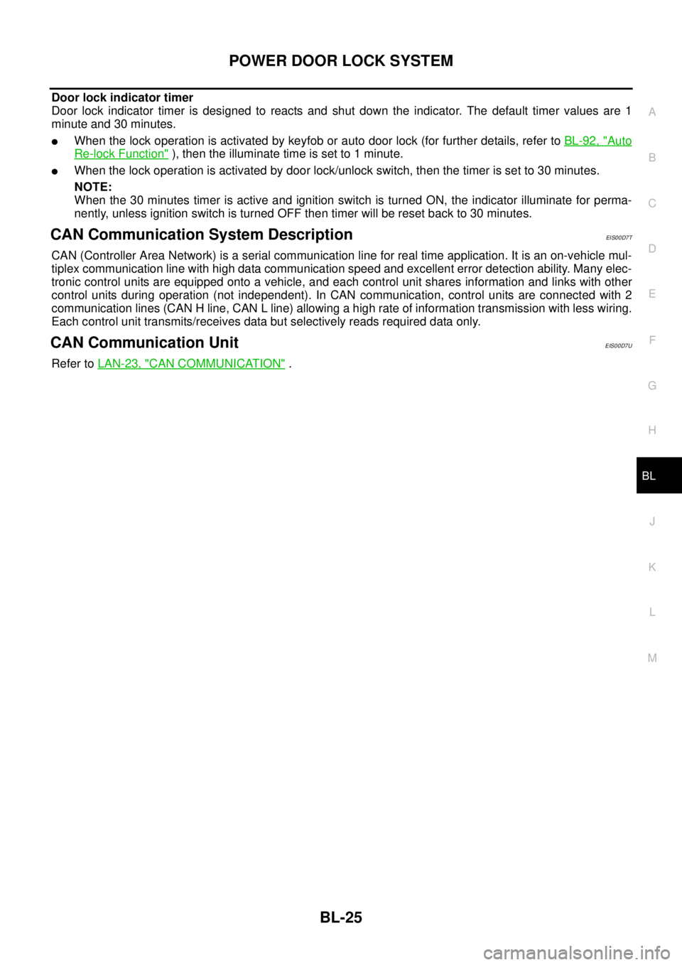
Door lock indicator timer
Door lock indicator timer is designed to reacts and shut down the indicator. The default timer values are 1
minute and 30 minutes.
lWhen the lock operation is activated by keyfob or auto door lock (for further details, refer toBL-92, "Auto
Re-lock Function"), then the illuminate time is set to 1 minute.
lWhen the lock operation is activated by door lock/unlock switch, then the timer is set to 30 minutes.
NOTE:
When the 30 minutes timer is active and ignition switch is turned ON, the indicator illuminate for perma-
nently, unless ignition switch is turned OFF then timer will be reset back to 30 minutes.
CAN Communication System DescriptionEIS00D7T
CAN (Controller Area Network) is a serial communication line for real time application. It is an on-vehicle mul-
tiplex communication line with high data communication speed and excellent error detection ability. Many elec-
tronic control units are equipped onto a vehicle, and each control unit shares information and links with other
control units during operation (not independent). In CAN communication, control units are connected with 2
communication lines (CAN H line, CAN L line) allowing a high rate of information transmission with less wiring.
Each control unit transmits/receives data but selectively reads required data only.
CAN Communication UnitEIS00D7U
Refer toLAN-23, "CAN COMMUNICATION".
Page 619 of 3171
POWERDOORLOCKSYSTEM
BL-35
C
D
E
F
G
H
J
K
L
MA
B
BL
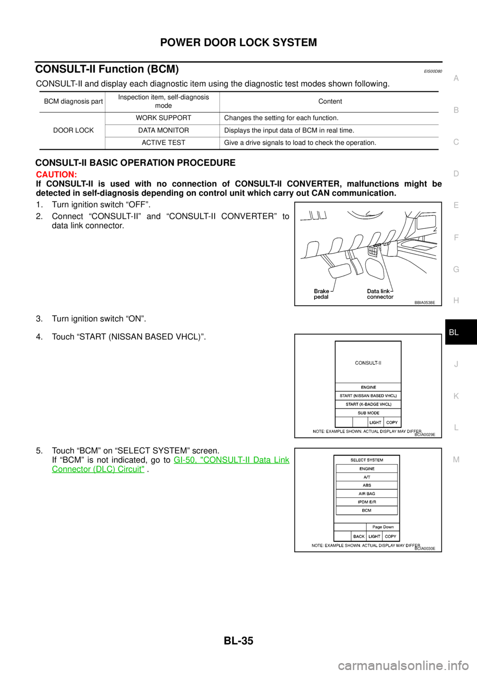
CONSULT-II Function (BCM)EIS00D80
CONSULT-II and display each diagnostic item using the diagnostic test modes shown following.
CONSULT-II BASIC OPERATION PROCEDURE
CAUTION:
If CONSULT-II is used with no connection of CONSULT-II CONVERTER, malfunctions might be
detected in self-diagnosis depending on control unit which carry out CAN communication.
1. Turn ignition switch “OFF”.
2. Connect “CONSULT-II” and “CONSULT-II CONVERTER” to
data link connector.
3. Turn ignition switch “ON”.
4. Touch “START (NISSAN BASED VHCL)”.
5. Touch “BCM” on “SELECT SYSTEM” screen.
If “BCM” is not indicated, go toGI-50, "
CONSULT-II Data Link
Connector (DLC) Circuit".
BCM diagnosis partInspection item, self-diagnosis
modeContent
DOOR LOCKWORK SUPPORT Changes the setting for each function.
DATA MONITOR Displays the input data of BCM in real time.
ACTIVE TEST Give a drive signals to load to check the operation.
BBIA0538E
BCIA0029E
BCIA0030E
Page 642 of 3171

BL-58
POWER DOOR LOCK — SUPER LOCK —
When door lock/unlock switch is locked, ground is supplied
lthrough BCM terminal 56
lthrough all door actuators terminal 3
lthrough all door lock actuators terminal 2
lthrough back door lock actuator terminals 1 and 3
lto BCM terminals 54 and 60.
then all doors actuators are locked
Power door unlock operation with door lock/unlock switch
When doors are unlock by door lock/unlock switch, ground is supplied
lto BCM terminal 32
lthrough door lock/unlock switch terminals 2 and 3
lthrough body grounds M21, M80 and M83.
then all doors are locked.
When door lock/unlock switch is unlocked, ground is supplied
lthrough BCM terminals 54 and 60
lthrough all door lock actuators terminal 2
lthrough all door lock actuators terminal 3
lthen all door actuators are unlock
lto BCM terminal 56.
Door lock/unlock switch indicator operation
When door lock/unlock switch is locked, all doors are locked, door lock/unlock switch indicator is on, and
ground is supplied
lto BCM terminal 17
lthrough door lock/unlock switch terminals 5 and 3
lthrough body grounds M21, M80 and M83.
OUTLINE
Power door lock systems with super lock function provides a higher anti-theft performance than conventional
power door lock systems. The super lock system is controlled by BCM (Body Control Module).
Pressing LOCK button on key fob once will lock all doors and activate super lock simultaneously.
When super lock is set, all doors cannot be opened from inside.
Pressing UNLOCK button once on key fob will unlock driver side door (unlock all doors if anti-hijack system is
disabled and during this state, super lock is still active). Second press on the UNLOCK button within 5 second
from the first will unlock all doors and release super lock simultaneously.
Functions Available By Operating the Door Lock/Unlock Switch
lOperating the door lock/unlock switch in the control panel will activate all doors actuator to lock or unlock.
If any doors are opened (except the driver side) during operating the door lock/unlock switch in lock direc-
tion, the door lock actuators will not response. Unlock via the interior door handles and door lock/unlock
switch is always possible.
lOperating the door lock/unlock switch to “LOCK” will lock the vehicle even while driver side door is
opened.
OPERATION
Set Super Lock Conditions
lWhen all these following conditions are met, BCM receives lock signal from key fob.
–All doors are closed.
–Key is out of the ignition key cylinder.
Release Super Lock Conditions
lBCM unit receives a valid unlock signal from key fob.
lIgnition switch is turned ON (door lock/unlock switch will remain its state, super lock is released).
NOTE:
Door lock/unlock switch is incapable of overriding super lock.