Page 548 of 3171
AV-60
DIAGNOSIS SYSTEM
AUDIO
lWhen “AUDIO” is selected, the communication condition from
audio unit to each unit and malfunction counter are displayed.
lError counter displays OK if any malfunction is not detected in
the past. If the malfunction is detected, it displays 0. When turn-
ing the ignition switch ON, if it is normal, it displays 1. The upper
limitofthecounteris39.
ECU PART NUMBER
The part number of NAVI control unit is displayed.
ItemsDisplay
(PRESENT)Malfunction
counter
(PAST)
TRANSMIT DG OK / UNKWN OK / 0 - 39
SPEAKER AMP — —
TV TUNER — —
DVD PLAYER — —
MD DECK — —
CD CHANGER — —
MD CHANGER — —
SKIB4685E
SKIB3680E
Page 549 of 3171

TROUBLE DIAGNOSIS
AV-61
C
D
E
F
G
H
I
J
L
MA
B
AV
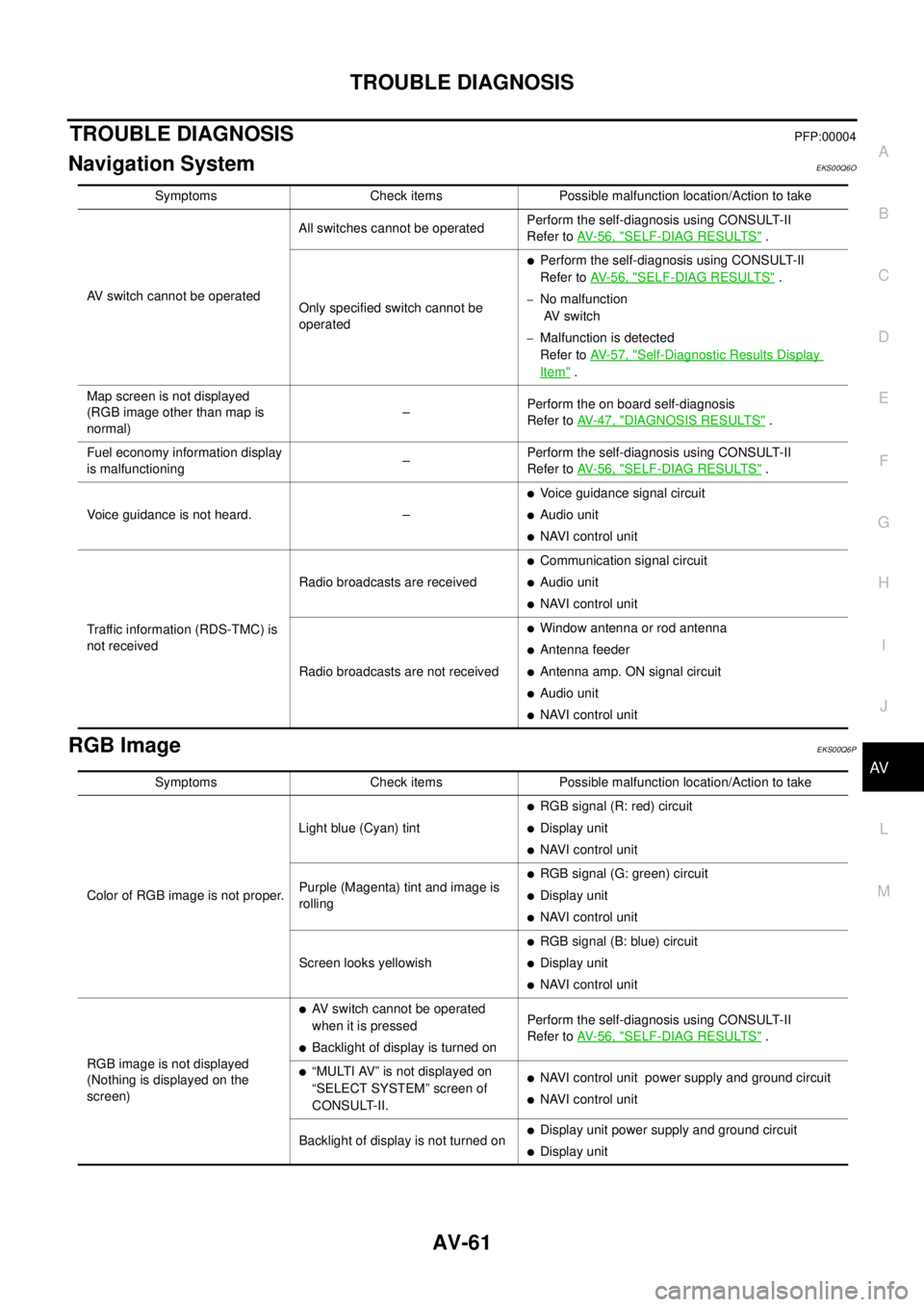
TROUBLE DIAGNOSISPFP:00004
Navigation SystemEKS00Q6O
RGB ImageEKS00Q6P
Symptoms Check items Possible malfunction location/Action to take
AV switch cannot be operatedAll switches cannot be operatedPerform the self-diagnosis using CONSULT-II
Refer toAV-56, "
SELF-DIAG RESULTS".
Only specified switch cannot be
operated
lPerform the self-diagnosis using CONSULT-II
Refer toAV-56, "
SELF-DIAG RESULTS".
–No malfunction
AV switch
–Malfunction is detected
Refer toAV-57, "
Self-Diagnostic Results Display
Item".
Map screen is not displayed
(RGB image other than map is
normal)–Perform the on board self-diagnosis
Refer toAV-47, "
DIAGNOSIS RESULTS".
Fuel economy information display
is malfunctioning–Perform the self-diagnosis using CONSULT-II
Refer toAV-56, "
SELF-DIAG RESULTS".
Voice guidance is not heard. –
lVoice guidance signal circuit
lAudio unit
lNAVI control unit
Traffic information (RDS-TMC) is
not receivedRadio broadcasts are received
lCommunication signal circuit
lAudio unit
lNAVI control unit
Radio broadcasts are not received
lWindow antenna or rod antenna
lAntenna feeder
lAntenna amp. ON signal circuit
lAudio unit
lNAVI control unit
Symptoms Check items Possible malfunction location/Action to take
Color of RGB image is not proper.Light blue (Cyan) tint
lRGB signal (R: red) circuit
lDisplay unit
lNAVI control unit
Purple (Magenta) tint and image is
rolling
lRGB signal (G: green) circuit
lDisplay unit
lNAVI control unit
Screen looks yellowish
lRGB signal (B: blue) circuit
lDisplay unit
lNAVI control unit
RGB image is not displayed
(Nothing is displayed on the
screen)
lAV switch cannot be operated
when it is pressed
lBacklight of display is turned onPerform the self-diagnosis using CONSULT-II
Refer toAV-56, "SELF-DIAG RESULTS".
l“MULTI AV” is not displayed on
“SELECT SYSTEM” screen of
CONSULT-II.lNAVI control unit power supply and ground circuit
lNAVI control unit
Backlight of display is not turned on
lDisplay unit power supply and ground circuit
lDisplay unit
Page 550 of 3171

AV-62
TROUBLE DIAGNOSIS
Voice Activated Control System
EKS00Q6Q
Symptoms Check items Probable malfunction location
The voice cannot be controlled
even if the voice control screen is
displayedVoice sounds at “Speaker Test” and
“Voice Microphone Test” of Confir-
mation/Adjustment modeNAVI control unit
Voice does not sound at “Speaker
Test” and “Voice Microphone Test” of
Confirmation/Adjustment mode
lMIC. power supply circuit
lShield (MIC.) circuit
lMIC. signal circuit
lMicrophone
lNAVI control unit
The voice cannot be controlled
(Voice control screen is not dis-
played)TEL operation screen is displayed by
pressing and holding “TEL/PPT”
switch of steering wheel switchNAVI control unit
lTEL operation screen is not dis-
played by pressing and holding
“TEL/PPT” switch of steering
wheel switch
lOther steering wheel switches are
normalSteering wheel switch
“BACK”, “VOL UP”, “VOL DOWN”,
and “TEL/PPT” switches of steering
wheel switch are not operated
lRemote control signal B circuit
lSteering wheel switch
lAudio unit
All steering wheel switches are not
operated
lRemote control signal ground circuit
lSteering wheel switch
lAudio unit
Page 551 of 3171

TROUBLE DIAGNOSIS
AV-63
C
D
E
F
G
H
I
J
L
MA
B
AV
Steering Wheel SwitchEKS00Q6R
Without NAVI
With NAVI
Component Parts InspectionEKS00Q6S
STEERING WHEEL SWITCH UNIT INSPECTION
lCheck continuity between combination switch harness connector M302 terminal 15 and terminal 16.
lCheck continuity between combination switch harness connector M302 terminal 14 and terminal 16.
Symptoms Probable malfunction location
All steering wheel switches are not operated
lRemote control signal ground circuit
lSteering wheel switch
lAudio unit
Only specified switch cannot be operated Steering wheel switch
“MODE”, “SEEK UP”, and “VOL UP” switches are not oper-
ated
lRemote control signal A circuit
lSteering wheel switch
lAudio unit
“SEEK DOWN”, and “VOL DOWN” switches are not oper-
ated
lRemote control signal B circuit
lSteering wheel switch
lAudio unit
Symptoms Probable malfunction location
All steering wheel switches are not operated
lRemote control signal ground circuit
lSteering wheel switch
lAudio unit
Only specified switch cannot be operated Steering wheel switch
“ENTER”, “MENU UP”, “MENU DOWN”, and “SOURCE”
switches are not operated
lRemote control signal A circuit
lSteering wheel switch
lAudio unit
“BACK”, “TEL /PPT”, “VOL UP”, and “VOL DOWN” switches
are not operated
lRemote control signal B circuit
lSteering wheel switch
lAudio unit
Page 563 of 3171
REMOVAL AND INSTALLATION
AV-75
C
D
E
F
G
H
I
J
L
MA
B
AV
Tw e e t e rEKS00Q6Z
REMOVAL
1. Remove speaker grille.
2. Remove screws (A) and remove tweeter (1).
INSTALLATION
Installation is the reverse order of removal.
Roof AntennaEKS00Q70
REMOVAL
l: Vehicle front
1. Remove headlining. Refer toEI-40, "
HEADLINING".
2. Remove nut (A) and antenna base.
INSTALLATION
Installation is the reverse order of removal.
NAVI Control UnitEKS00Q71
REMOVAL
l: Vehicle front
1. Slide front seat RH fully forward.
2. Disconnect connectors.
3. Remove screws (A) and remove NAVI control unit (1).
4. Remove screws and brackets (2) from NAVI control unit (1).
INSTALLATION
Installation is the reverse order of removal.
SKIB4581E
SKIB6657E
SKIB4531E
Page 569 of 3171

BCM (BODY CONTROL MODULE)
BCS-3
C
D
E
F
G
H
I
J
L
MA
B
BCS
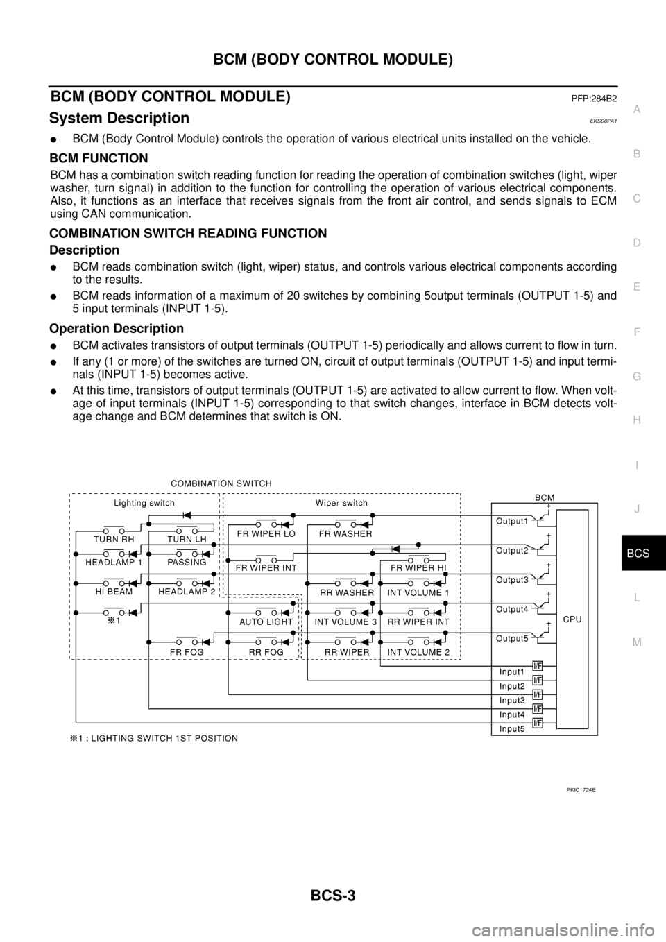
BCM (BODY CONTROL MODULE)PFP:284B2
System DescriptionEKS00PA1
lBCM (Body Control Module) controls the operation of various electrical units installed on the vehicle.
BCM FUNCTION
BCM has a combination switch reading function for reading the operation of combination switches (light, wiper
washer, turn signal) in addition to the function for controlling the operation of various electrical components.
Also, it functions as an interface that receives signals from the front air control, and sends signals to ECM
using CAN communication.
COMBINATION SWITCH READING FUNCTION
Description
lBCM reads combination switch (light, wiper) status, and controls various electrical components according
to the results.
lBCM reads information of a maximum of 20 switches by combining 5output terminals (OUTPUT 1-5) and
5 input terminals (INPUT 1-5).
Operation Description
lBCM activates transistors of output terminals (OUTPUT 1-5) periodically and allows current to flow in turn.
lIf any (1 or more) of the switches are turned ON, circuit of output terminals (OUTPUT 1-5) and input termi-
nals (INPUT 1-5) becomes active.
lAt this time, transistors of output terminals (OUTPUT 1-5) are activated to allow current to flow. When volt-
age of input terminals (INPUT 1-5) corresponding to that switch changes, interface in BCM detects volt-
age change and BCM determines that switch is ON.
PKIC1724E
Page 572 of 3171
BCS-6
BCM (BODY CONTROL MODULE)
Operation Mode
lCombination switch reading function has operation modes as follows:
Normal status
lWhen BCM is not in sleep status, OUTPUT terminals (1-5) each turn ON-OFF every 10 ms.
Sleep status
lWhen BCM is in sleep mode, BCM enters low power mode. OUTPUTS 1-5 turn ON-OFF at 22 ms inter-
vals, and receives lighting switch input only.
CAN COMMUNICATION CONTROL
CAN communication allows a high rate of information through the two communication lines (CAN-L, CAN-H)
connecting the various control units in the system. Each control unit transmits/receives data, but selectively
reads required data only.
PKIC0489E
Page 573 of 3171

BCM (BODY CONTROL MODULE)
BCS-7
C
D
E
F
G
H
I
J
L
MA
B
BCS
BCM STATUS CONTROL
BCM changes its status depending on the operation status in order to save power consumption.
1. CAN communication status
lWith ignition switch ON, CAN communicates with other control units normally.
lControl by BCM is being operated properly.
lWhen ignition switch is OFF, switching to sleep mode is possible.
lEven when ignition switch is OFF, if CAN communication with IPDM E/R and combination meter is
active, CAN communication status is active.
2. Sleep transient status
lThis status shuts down CAN communication when ignition switch is turned OFF.
lIt transmits sleep request signal to IPDM E/R and combination meter.
lTwo seconds after CAN communication of all control units stops, CAN communication switches to inac-
tive status.
3. CAN communication inactive status
lWith ignition switch OFF, CAN communication is not active.
lWith ignition switch OFF, control performed only by BCM is active.
lThree seconds after CAN communication of all control units stops, CAN communication switches to
inactive status.
4. Sleep status
lBCM is activated with low current consumption mode.
lCAN communication is not active.
lWhen CAN communication operation is detected, it switches to CAN communication status.
lWhen a state of the following switches changes, it switches to CAN communication state:
–Key switch
–Hazard switch
–Door lock/unlock switch
–Front door switch (driver side, passenger side)
–Rear door switch (LH, RH) (double cab)
–Rear door switch (driver side, passenger side) No.1 (king cab)
–Rear door switch (driver side, passenger side) No.2 (king cab)
–Combination switch (passing, lighting switch 1st position, front fog lamp)
–Keyfob (lock/unlock signal)
–Door lock assembly LH (key cylinder switch)
lWhen control performed only by BCM is required by switch, it shifts to CAN communication inactive
mode.
lStatus of combination switch reading function is changed.