2005 NISSAN NAVARA control unit
[x] Cancel search: control unitPage 643 of 3171
POWER DOOR LOCK — SUPER LOCK —
BL-59
C
D
E
F
G
H
J
K
L
MA
B
BL
Door Lock Warning Function
Under following conditions lock actuators will not response and buzzer warning will beeps while pressing door
lock/unlock switch in LOCK direction.
lIgnition switch is turned OFF
lMechanical key is out of ignition key cylinder
lAny door is opened (except driver side door)
Key Reminder Function
Under following conditions lock actuators will lock the door once, but then immediately unlock all doors and
buzzer warning will beeps while pressing door lock/unlock switch in LOCK direction.
lIgnition switch is turned OFF
lMechanical key is inserted in ignition key cylinder
lDriver side door is opened
Door Lock/Unlock Switch Indicator
The Door lock/unlock switch indicates door lock status. The indicator will illuminate when a lock operation is
accomplish, during this state, if any door is open, the indicator will turn OFF.
Door Lock Indicator Timer
Door lock indicator timer is designed to reacts and shut down the indicator. The default timer values are 1
minute and 30 minutes.
lWhen the lock operation is activated by keyfob or auto door lock (for further details refer toBL-92, "Auto
Re-lock Function"), then the illuminate time is set to 1 minute.
lWhen the lock operation is activated by door lock/unlock switch, then the timer is set to 30 minutes.
NOTE:
When the 30 minutes timer is active and ignition switch is turned ON, then the indicator illuminate for per-
manently unless ignition switch is turned OFF then timer will be reset back to 30 minutes.
CAN Communication System DescriptionEIS00DX1
CAN (Controller Area Network) is a serial communication line for real time application. It is an on-vehicle mul-
tiplex communication line with high data communication speed and excellent error detection ability. Many elec-
tronic control units are equipped onto a vehicle, and each control unit shares information and links with other
control units during operation (not independent). In CAN communication, control units are connected with 2
communication lines (CAN H line, CAN L line) allowing a high rate of information transmission with less wiring.
Each control unit transmits/receives data but selectively reads required data only.
CAN Communication UnitEIS00DX2
Refer toLAN-23, "CAN COMMUNICATION".
Page 654 of 3171
BL-70
POWER DOOR LOCK — SUPER LOCK —
CONSULT-II Function (BCM)
EIS00DX6
CONSULT-II and display each diagnostic item using the diagnostic test modes shown following.
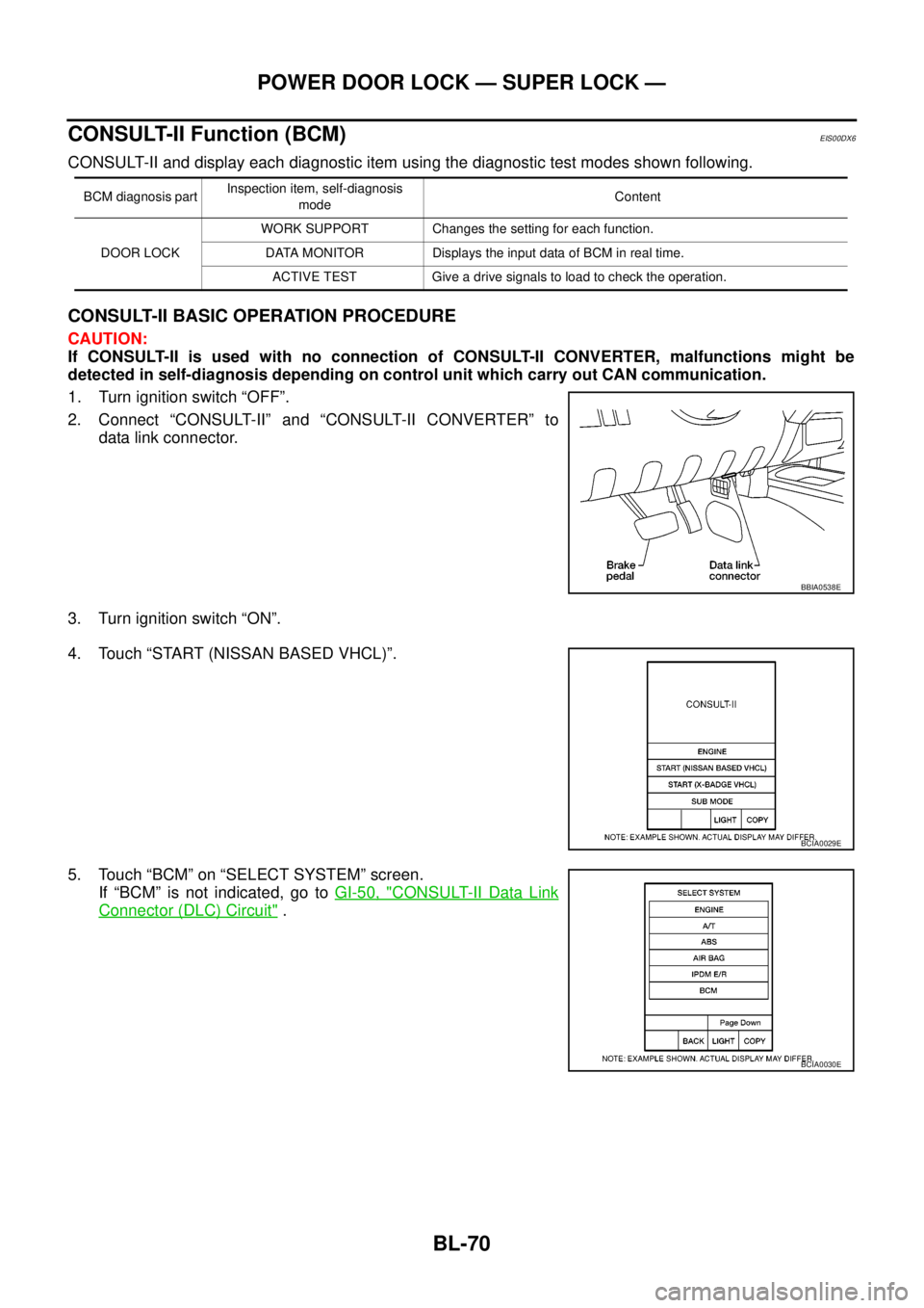
CONSULT-II BASIC OPERATION PROCEDURE
CAUTION:
If CONSULT-II is used with no connection of CONSULT-II CONVERTER, malfunctions might be
detected in self-diagnosis depending on control unit which carry out CAN communication.
1. Turn ignition switch “OFF”.
2. Connect “CONSULT-II” and “CONSULT-II CONVERTER” to
data link connector.
3. Turn ignition switch “ON”.
4. Touch “START (NISSAN BASED VHCL)”.
5. Touch “BCM” on “SELECT SYSTEM” screen.
If “BCM” is not indicated, go toGI-50, "
CONSULT-II Data Link
Connector (DLC) Circuit".
BCM diagnosis partInspection item, self-diagnosis
modeContent
DOOR LOCKWORK SUPPORT Changes the setting for each function.
DATA MONITOR Displays the input data of BCM in real time.
ACTIVE TEST Give a drive signals to load to check the operation.
BBIA0538E
BCIA0029E
BCIA0030E
Page 686 of 3171
BL-102
MULTI-REMOTE CONTROL SYSTEM
CONSULT-II Function (BCM)
EIS00DBJ
CONSULT-II can display each diagnostic item using the diagnostic test modes shown following.
CONSULT-II Inspection ProcedureEIS00DBK
“MULTI REMOTE ENT”
CAUTION:
If CONSULT-II is used with no connection of CONSULT-II CONVERTER, malfunctions might be
detected in self-diagnosis depending on control unit which carry out CAN communication.
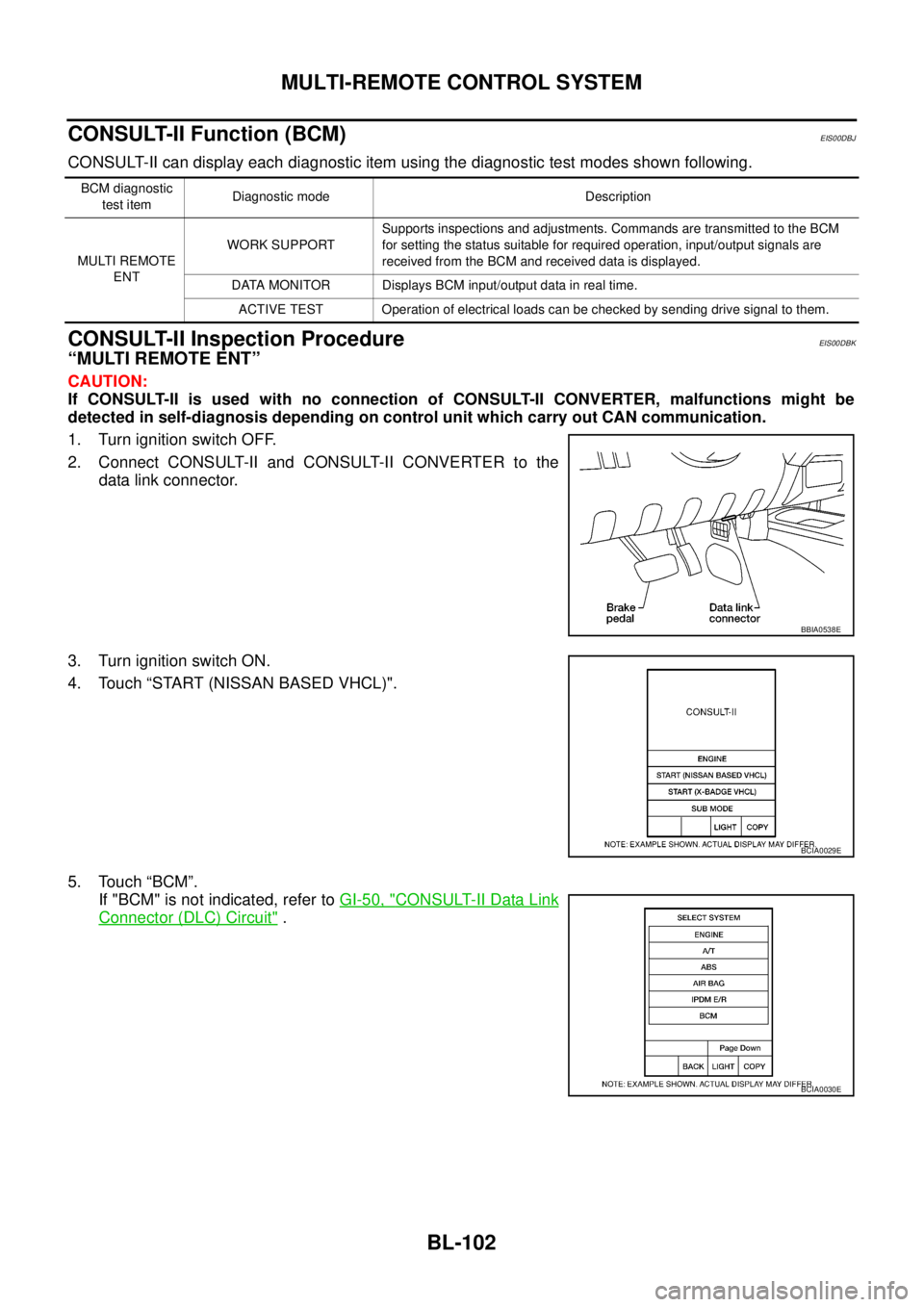
1. Turn ignition switch OFF.
2. Connect CONSULT-II and CONSULT-II CONVERTER to the
data link connector.
3. Turn ignition switch ON.
4. Touch “START (NISSAN BASED VHCL)".
5. Touch “BCM”.
If "BCM" is not indicated, refer toGI-50, "
CONSULT-II Data Link
Connector (DLC) Circuit".
BCM diagnostic
test itemDiagnostic mode Description
MULTI REMOTE
ENTWORK SUPPORTSupports inspections and adjustments. Commands are transmitted to the BCM
for setting the status suitable for required operation, input/output signals are
received from the BCM and received data is displayed.
DATA MONITOR Displays BCM input/output data in real time.
ACTIVE TEST Operation of electrical loads can be checked by sending drive signal to them.
BBIA0538E
BCIA0029E
BCIA0030E
Page 724 of 3171
BL-140
THEFT WARNING SYSTEM
System Description
EIS00DBX
DESCRIPTION
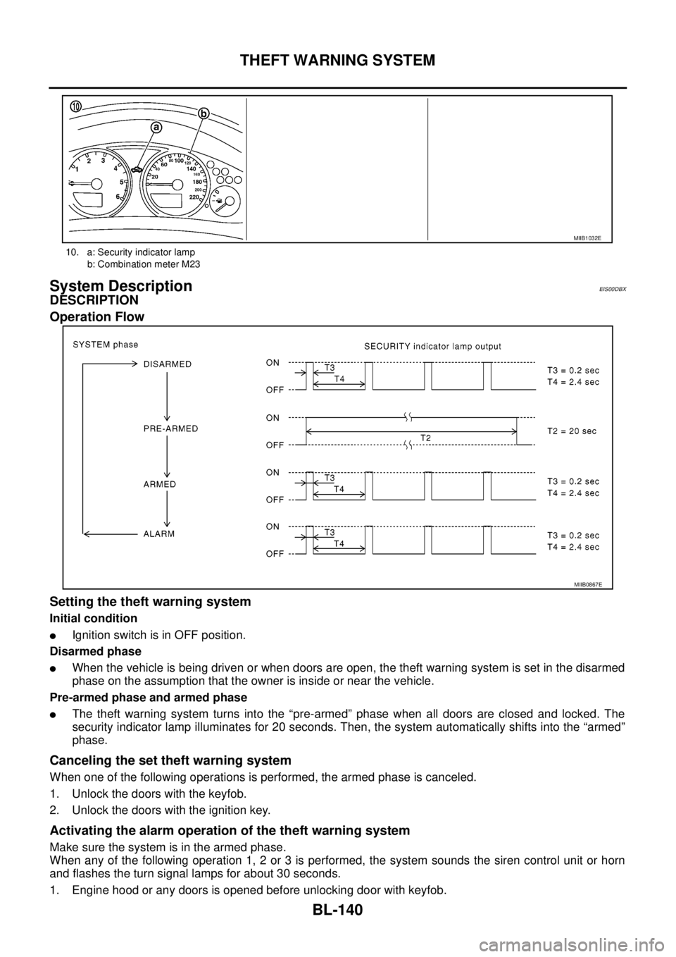
Operation Flow
Setting the theft warning system
Initial condition
lIgnition switch is in OFF position.
Disarmed phase
lWhen the vehicle is being driven or when doors are open, the theft warning system is set in the disarmed
phase on the assumption that the owner is inside or near the vehicle.
Pre-armed phase and armed phase
lThe theft warning system turns into the “pre-armed” phase when all doors are closed and locked. The
security indicator lamp illuminates for 20 seconds. Then, the system automatically shifts into the “armed”
phase.
Canceling the set theft warning system
When one of the following operations is performed, the armed phase is canceled.
1. Unlock the doors with the keyfob.
2. Unlock the doors with the ignition key.
Activating the alarm operation of the theft warning system
Make sure the system is in the armed phase.
When any of the following operation 1, 2 or 3 is performed, the system sounds the siren control unit or horn
and flashes the turn signal lamps for about 30 seconds.
1. Engine hood or any doors is opened before unlocking door with keyfob.
10. a: Security indicator lamp
b: Combination meter M23
MIIB1032E
MIIB0867E
Page 725 of 3171

THEFT WARNING SYSTEM
BL-141
C
D
E
F
G
H
J
K
L
MA
B
BL
2. A door is unlocked without using the keyfob.
3. Disconnect and connecting the battery connector before canceling armed phase.
POWER SUPPLY AND GROUND CIRCUIT
Power is supplied at all times
lthrough 10A fuse [No.19, located in the fuse block (J/B)]
lto combination meter (security indicator lamp) terminal 3
lthrough 50A fusible link (letterG, located in the fuse and fusible link box)
lto BCM terminal 57
lthrough 10A fuse [No. 21, located in the fuse block (J/B)]
lto BCM terminal 41
lthrough 15A fuse (No. 30, located in the fuse and fusible link box)
lto horn relay terminal 2
lthrough 20A fuse (No. 52, located in the IPDM E/R)
lthrough 20A fuse (No. 53, located in the IPDM E/R),
lto IPDM E/R internal CPU.
With the ignition switch in the ACC or ON position, power is supplied
lthrough 10A fuse [No. 4, located in the fuse block (J/B)]
lto BCM terminal 4.
Ground is supplied
lto BCM terminal 55
lthrough body grounds M21, M80 and M83
lto IPDM E/R terminals 38 and 59
lthrough body ground E21, E41 and E61.
INITIAL CONDITION TO ACTIVATE THE SYSTEM
The operation of the theft warning system is controlled by the engine hood and doors.
To activate the theft warning system, BCM must receive signals indicating the doors are closed and locked.
When a door is open, BCM terminal 12, 14, 15 or 16 receives a ground signal from each door switch.
When the engine hood is open, IPDM E/R terminal 41 receives a ground signal
THEFT WARNING SYSTEM ALARM OPERATION
The vehicle security system is triggered by
lopening a door
lopening the hood
ldetecting battery disconnect/connection.
The vehicle security system will be triggered once the system is in armed phase,
when BCM receives a ground signal at terminals 12, 14, 15, 16 (door switch) or IPDM E/R receives a ground
signal at terminal 41 (hood switch).
When the vehicle security system is triggered, siren control unit or horn is activate.
The alarm automatically turns off after 30 seconds, but will reactivate if the vehicle is tampered with again.
THEFT WARNING SYSTEM DEACTIVATION
To deactivate the theft warning system, a door must be unlocked with keyfob.
When the BCM receives either one of these signals or unlock signal from keyfob the theft warning system is
deactivated. (Disarmed phase)
CAN Communication System DescriptionEIS00DBY
Refer toLAN-23, "CAN COMMUNICATION".
Page 740 of 3171
BL-156
THEFT WARNING SYSTEM
TerminalsandReferenceValueforIPDME/R
EIS00DC3
*: When horn reminder is ON.
CONSULT-II Function (BCM)EIS00DC4
CONSULT-II can display each diagnostic item using the diagnostic test modes shown following.
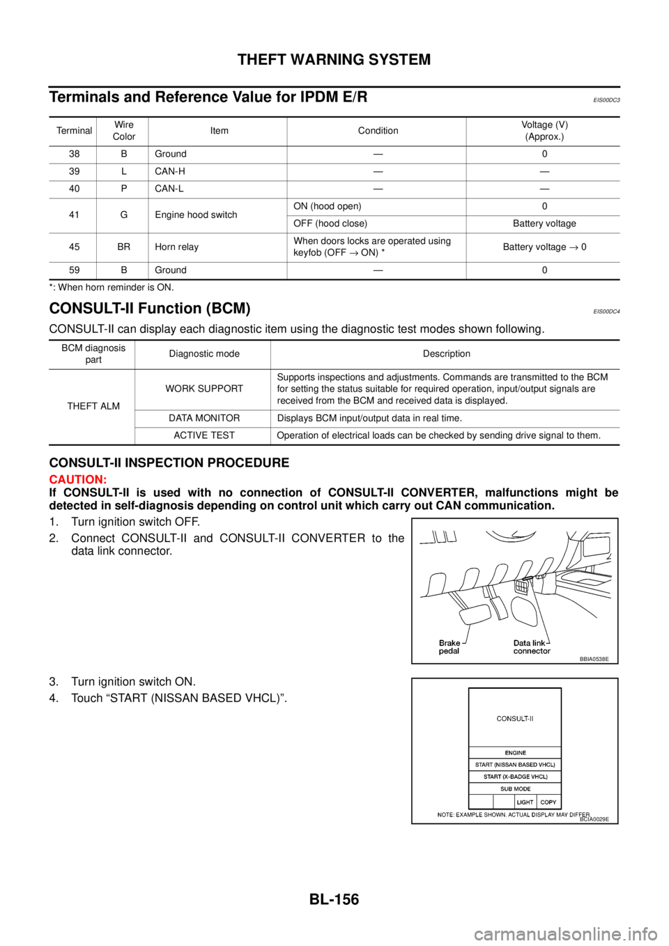
CONSULT-II INSPECTION PROCEDURE
CAUTION:
If CONSULT-II is used with no connection of CONSULT-II CONVERTER, malfunctions might be
detected in self-diagnosis depending on control unit which carry out CAN communication.
1. Turn ignition switch OFF.
2. Connect CONSULT-II and CONSULT-II CONVERTER to the
data link connector.
3. Turn ignition switch ON.
4. Touch “START (NISSAN BASED VHCL)”.
TerminalWire
ColorItem ConditionVoltage (V)
(Approx.)
38 B Ground — 0
39 L CAN-H — —
40 P CAN-L — —
41 G Engine hood switchON (hood open) 0
OFF (hood close) Battery voltage
45 BR Horn relayWhen doors locks are operated using
keyfob (OFF®ON) *Battery voltage®0
59 B Ground — 0
BCM diagnosis
partDiagnostic mode Description
THEFT ALMWORK SUPPORTSupports inspections and adjustments. Commands are transmitted to the BCM
for setting the status suitable for required operation, input/output signals are
received from the BCM and received data is displayed.
DATA MONITOR Displays BCM input/output data in real time.
ACTIVE TEST Operation of electrical loads can be checked by sending drive signal to them.
BBIA0538E
BCIA0029E
Page 756 of 3171
BL-172
NATS(NISSAN ANTI-THEFT SYSTEM)
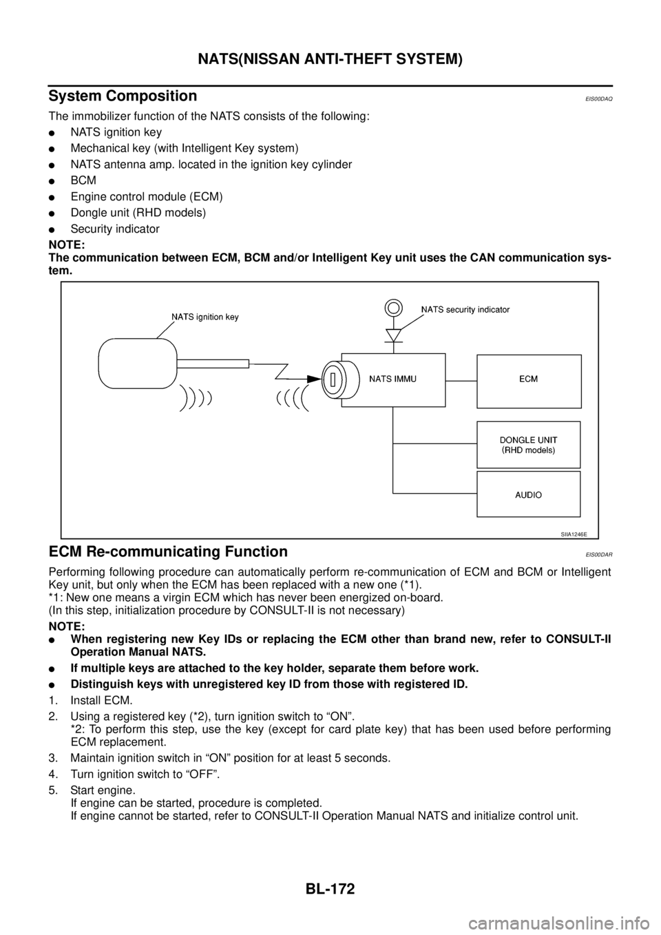
System Composition
EIS00DAQ
The immobilizer function of the NATS consists of the following:
lNATS ignition key
lMechanical key (with Intelligent Key system)
lNATS antenna amp. located in the ignition key cylinder
lBCM
lEngine control module (ECM)
lDongle unit (RHD models)
lSecurity indicator
NOTE:
The communication between ECM, BCM and/or Intelligent Key unit uses the CAN communication sys-
tem.
ECM Re-communicating FunctionEIS00DAR
Performing following procedure can automatically perform re-communication of ECM and BCM or Intelligent
Key unit, but only when the ECM has been replaced with a new one (*1).
*1: New one means a virgin ECM which has never been energized on-board.
(In this step, initialization procedure by CONSULT-II is not necessary)
NOTE:
lWhen registering new Key IDs or replacing the ECM other than brand new, refer to CONSULT-II
Operation Manual NATS.
lIf multiple keys are attached to the key holder, separate them before work.
lDistinguish keys with unregistered key ID from those with registered ID.
1. Install ECM.
2. Usingaregisteredkey(*2),turnignitionswitchto“ON”.
*2: To perform this step, use the key (except for card plate key) that has been used before performing
ECM replacement.
3. Maintain ignition switch in “ON” position for at least 5 seconds.
4. Turn ignition switch to “OFF”.
5. Start engine.
If engine can be started, procedure is completed.
If engine cannot be started, refer to CONSULT-II Operation Manual NATS and initialize control unit.
SIIA1246E
Page 789 of 3171
PRECAUTIONS
BR-3
C
D
E
G
H
I
J
K
L
MA
B
BR
PRECAUTIONSPFP:00001
Precautions for Supplemental Restraint System (SRS) “AIR BAG” and “SEAT
BELT PRE-TENSIONER”
EFS006DL
The Supplemental Restraint System such as “AIR BAG” and “SEAT BELT PRE-TENSIONER”, used along
with a front seat belt, helps to reduce the risk or severity of injury to the driver and front passenger for certain
types of collision. Information necessary to service the system safely is included in the SRS and SB section of
this Service Manual.
WARNING:
lTo avoid rendering the SRS inoperative, which could increase the risk of personal injury or death
in the event of a collision which would result in air bag inflation, all maintenance must be per-
formed by an authorized NISSAN/INFINITI dealer.
lImproper maintenance, including incorrect removal and installation of the SRS, can lead to per-
sonal injury caused by unintentional activation of the system. For removal of Spiral Cable and Air
Bag Module, see the SRS section.
lDo not use electrical test equipment on any circuit related to the SRS unless instructed to in this
Service Manual. SRS wiring harnesses can be identified by yellow and/or orange harnesses or
harness connectors.
Precautions for Brake SystemEFS005SD
lClean dust on front brake and rear brake with a vacuum dust collector. Do not blow with compressed air.
lRecommended fluid is brake fluid “DOT 3” or “DOT 4”.
lNever reuse drained brake fluid.
lBe careful not to splash brake fluid on painted areas; it may cause paint damage. If brake fluid is splashed
on painted areas, wash it away with water immediately.
lTo clean or wash all parts of master cylinder, disc brake caliper, wheel cylinder, use new brake fluid.
lNever use mineral oils such as gasoline or kerosene. They will ruin rubber parts of the hydraulic system.
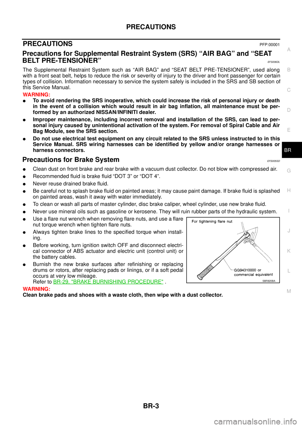
lUse a flare nut wrench when removing flare nuts, and use a flare
nut torque wrench when tighten flare nuts.
lAlways tighten brake lines to the specified torque when install-
ing.
lBefore working, turn ignition switch OFF and disconnect electri-
cal connector of ABS actuator and electric unit (control unit) or
the battery cables.
lBurnish the new brake surfaces after refinishing or replacing
drums or rotors, after replacing pads or linings, or if a soft pedal
occurs at very low mileage.
Refer toBR-29, "
BRAKE BURNISHING PROCEDURE".
WARNING:
Clean brake pads and shoes with a waste cloth, then wipe with a dust collector.SBR820BA