Page 659 of 3171
POWER DOOR LOCK — SUPER LOCK —
BL-75
C
D
E
F
G
H
J
K
L
MA
B
BL
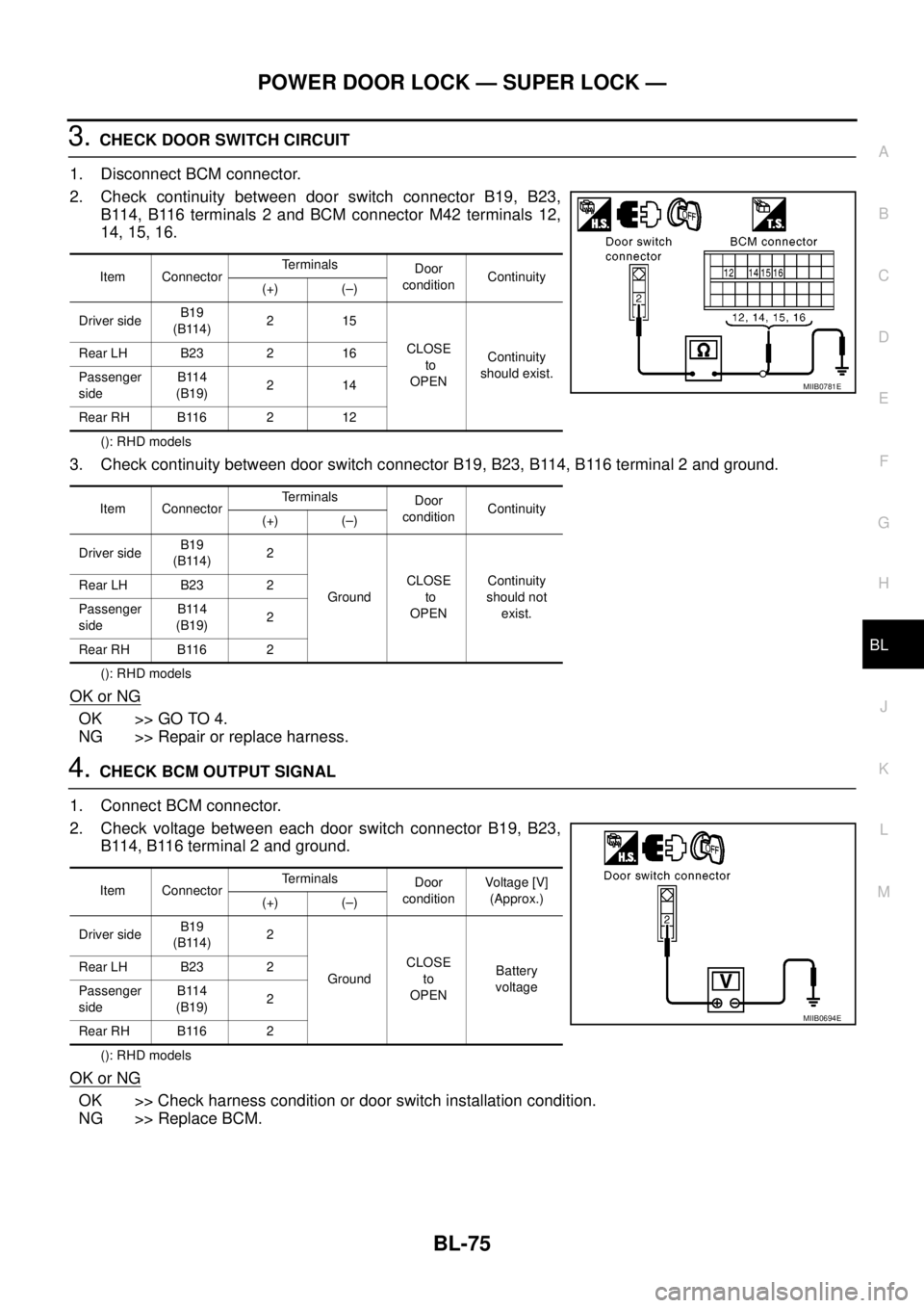
3.CHECK DOOR SWITCH CIRCUIT
1. Disconnect BCM connector.
2. Check continuity between door switch connector B19, B23,
B114, B116 terminals 2 and BCM connector M42 terminals 12,
14, 15, 16.
(): RHD models
3. Check continuity between door switch connector B19, B23, B114, B116 terminal 2 and ground.
(): RHD models
OK or NG
OK >> GO TO 4.
NG >> Repair or replace harness.
4.CHECK BCM OUTPUT SIGNAL
1. Connect BCM connector.
2. Check voltage between each door switch connector B19, B23,
B114, B116 terminal 2 and ground.
(): RHD models
OK or NG
OK >> Check harness condition or door switch installation condition.
NG >> Replace BCM.
Item ConnectorTerminals
Door
conditionContinuity
(+) (–)
Driver sideB19
(B114)215
CLOSE
to
OPENContinuity
should exist. Rear LH B23 2 16
Passenger
sideB114
(B19)214
Rear RH B116 2 12
Item ConnectorTerminals
Door
conditionContinuity
(+) (–)
Driver sideB19
(B114)2
GroundCLOSE
to
OPENContinuity
should not
exist. Rear LH B23 2
Passenger
sideB114
(B19)2
Rear RH B116 2
MIIB0781E
Item ConnectorTerminals
Door
conditionVoltag e [V]
(Approx.)
(+) (–)
Driver sideB19
(B114)2
GroundCLOSE
to
OPENBattery
voltage Rear LH B23 2
Passenger
sideB114
(B19)2
Rear RH B116 2
MIIB0694E
Page 660 of 3171
BL-76
POWER DOOR LOCK — SUPER LOCK —
CHECK DOOR SWITCH (KING CAB)
1.CHECK DOOR SWITCHES INPUT SIGNAL
With CONSULT-II
Check door switches (“DOOR SW-DR”, “DOOR SW-AS”) in DATA MONITOR mode with CONSULT-II. Refer
toBL-71, "
Data Monitor".
lWhen any doors are open:
lWhen any doors are closed:
Without CONSULT-II
Check voltage between door switch connector D74 (Front LH), D94 (Front RH) terminal 2, D72 (Rear upper
LH), D92 (Rear upper RH), D71 (Rear lower LH), D91 (Rear lower RH) terminals 1, 2 and ground.
(): RHD MODELS
OK or NG
OK >> System is OK.
NG >> GO TO 2.DOOR SW-DR : OFF
DOOR SW-AS : OFF
DOOR SW-DR : OFF
DOOR SW-AS : OFF
WIIA0560E
Item ConnectorTerminals
ConditionVoltage (V)
(Approx.)
(+) (-)
Front door
switch LHD74
(D94)
2
GroundOpen
¯
Closed0
¯
Battery
voltage Front door
switch RHD94
(D74)
Rear door
switch No.2 LHD72
(D92)
Rear door
switch No.2 RHD92
(D72)
1 Rear door
switch No.1 LHD71
(D91)
Rear door
switch No.1 RHD91
(D71)
MIIB1062E
Page 662 of 3171
BL-78
POWER DOOR LOCK — SUPER LOCK —
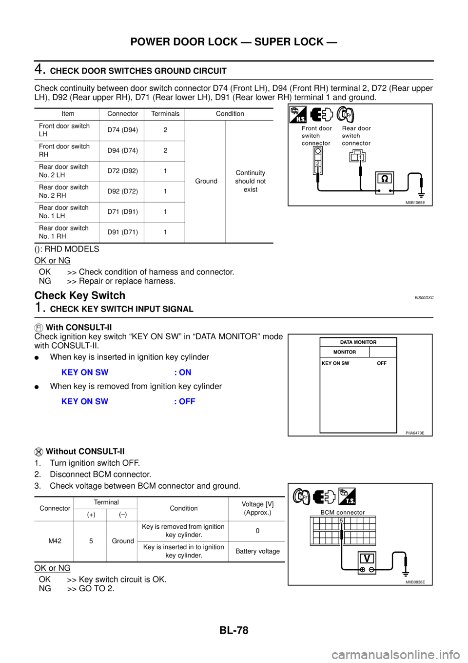
4.CHECK DOOR SWITCHES GROUND CIRCUIT
Check continuity between door switch connector D74 (Front LH), D94 (Front RH) terminal 2, D72 (Rear upper
LH), D92 (Rear upper RH), D71 (Rear lower LH), D91 (Rear lower RH) terminal 1 and ground.
(): RHD MODELS
OK or NG
OK >> Check condition of harness and connector.
NG >> Repair or replace harness.
Check Key SwitchEIS00DXC
1.CHECK KEY SWITCH INPUT SIGNAL
With CONSULT-II
Check ignition key switch “KEY ON SW” in “DATA MONITOR” mode
with CONSULT-II.
lWhen key is inserted in ignition key cylinder
lWhen key is removed from ignition key cylinder
Without CONSULT-II
1. Turn ignition switch OFF.
2. Disconnect BCM connector.
3. Check voltage between BCM connector and ground.
OK or NG
OK >> Key switch circuit is OK.
NG >> GO TO 2.
Item Connector Terminals Condition
Front door switch
LHD74 (D94) 2
GroundContinuity
should not
exist Front door switch
RHD94 (D74) 2
Rear door switch
No. 2 LHD72 (D92) 1
Rear door switch
No. 2 RHD92 (D72) 1
Rear door switch
No. 1 LHD71 (D91) 1
Rear door switch
No. 1 RHD91 (D71) 1
MIIB1065E
KEY ON SW : ON
KEY ON SW : OFF
PIIA6470E
ConnectorTerminal
ConditionVoltage [V]
(Approx.)
(+) (–)
M42 5 GroundKey is removed from ignition
key cylinder.0
Key is inserted in to ignition
key cylinder.Battery voltage
MIIB0838E
Page 664 of 3171
BL-80
POWER DOOR LOCK — SUPER LOCK —
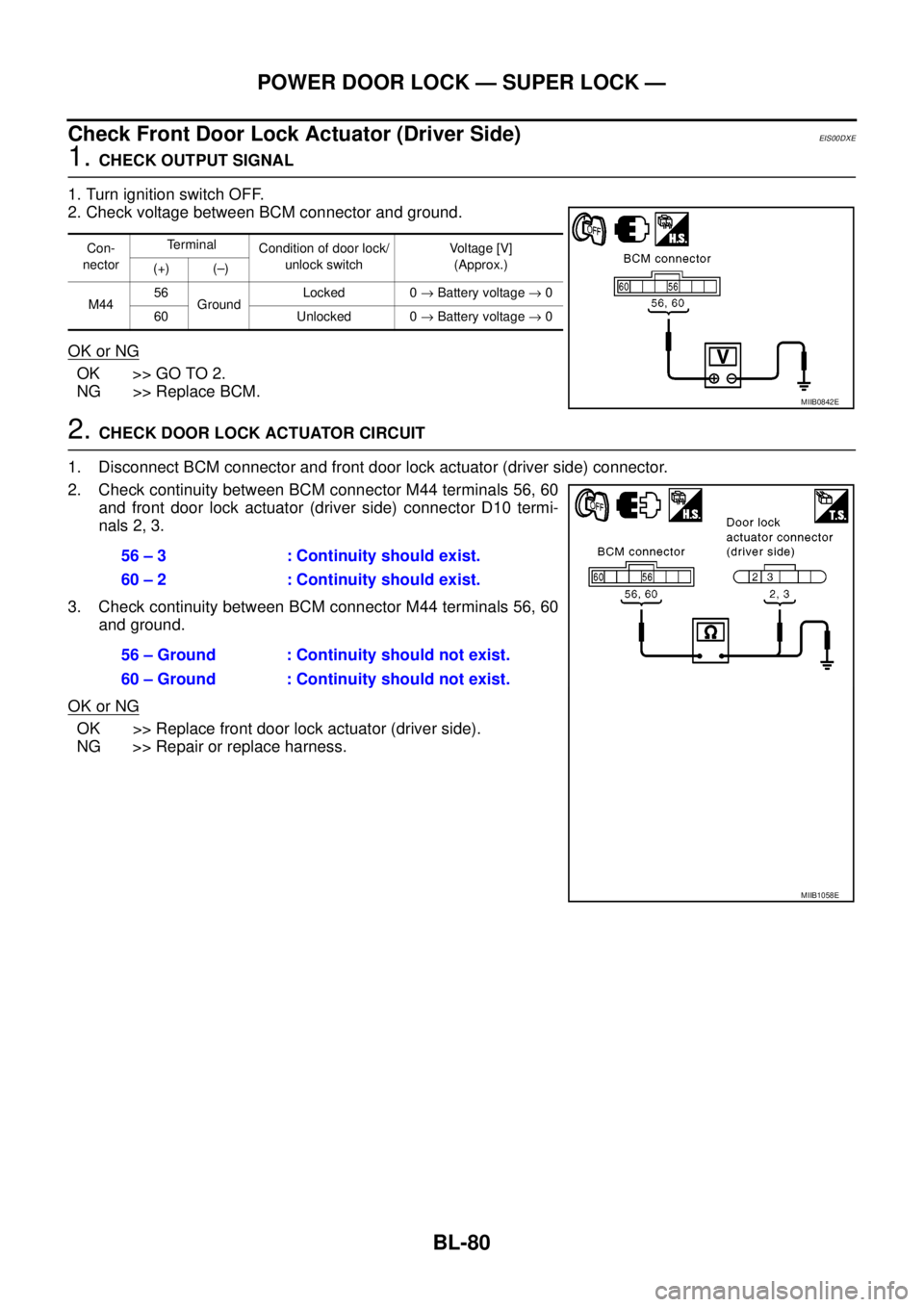
Check Front Door Lock Actuator (Driver Side)
EIS00DXE
1.CHECK OUTPUT SIGNAL
1. Turn ignition switch OFF.
2. Check voltage between BCM connector and ground.
OK or NG
OK >> GO TO 2.
NG >> Replace BCM.
2.CHECK DOOR LOCK ACTUATOR CIRCUIT
1. Disconnect BCM connector and front door lock actuator (driver side) connector.
2. Check continuity between BCM connector M44 terminals 56, 60
and front door lock actuator (driver side) connector D10 termi-
nals 2, 3.
3. Check continuity between BCM connector M44 terminals 56, 60
and ground.
OK or NG
OK >> Replace front door lock actuator (driver side).
NG >> Repair or replace harness.
Con-
nectorTerminal
Condition of door lock/
unlock switchVo l ta g e [V ]
(Approx.)
(+) (–)
M4456
GroundLocked 0®Battery voltage®0
60 Unlocked 0®Battery voltage®0
MIIB0842E
56 – 3 : Continuity should exist.
60 – 2 : Continuity should exist.
56 – Ground : Continuity should not exist.
60 – Ground : Continuity should not exist.
MIIB1058E
Page 665 of 3171
POWER DOOR LOCK — SUPER LOCK —
BL-81
C
D
E
F
G
H
J
K
L
MA
B
BL
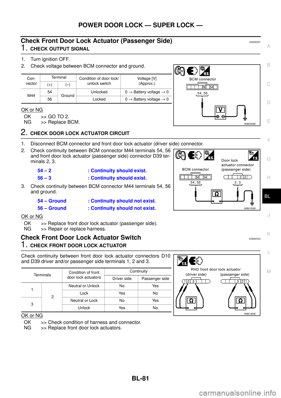
Check Front Door Lock Actuator (Passenger Side)EIS00DXF
1.CHECK OUTPUT SIGNAL
1. Turn ignition OFF.
2. Check voltage between BCM connector and ground.
OK or NG
OK >> GO TO 2.
NG >> Replace BCM.
2.CHECK DOOR LOCK ACTUATOR CIRCUIT
1. Disconnect BCM connector and front door lock actuator (driver side) connector.
2. Check continuity between BCM connector M44 terminals 54, 56
and front door lock actuator (passenger side) connector D39 ter-
minals 2, 3.
3. Check continuity between BCM connector M44 terminals 54, 56
and ground.
OK or NG
OK >> Replace front door lock actuator (passenger side).
NG >> Repair or replace harness.
Check Front Door Lock Actuator SwitchEIS00DXG
1.CHECK FRONT DOOR LOCK ACTUATOR
Check continuity between front door lock actuator connectors D10
and D39 driver and/or passenger side terminals 1, 2 and 3.
OK or NG
OK >> Check condition of harness and connector.
NG >> Replace front door lock actuators.
Con-
nectorTerminal
Condition of door lock/
unlock switchVoltag e [V]
(Approx.)
(+) (–)
M4454
GroundUnlocked 0®Battery voltage®0
56 Locked 0®Battery voltage®0
MIIB0849E
54 – 2 : Continuity should exist.
56 – 3 : Continuity should exist.
54 – Ground : Continuity should not exist.
56 – Ground : Continuity should not exist.
MIIB1059E
TerminalsCondition of front
door lock actuatorsContinuity
Driver side Passenger side
1
2Neutral or Unlock No Yes
Lock Yes No
3Neutral or Lock No Yes
Unlock Yes No
MIIB1060E
Page 667 of 3171
POWER DOOR LOCK — SUPER LOCK —
BL-83
C
D
E
F
G
H
J
K
L
MA
B
BL
Check RH and LH Rear Door Lock Actuator Switch (Double Cab Models)EIS00DXJ
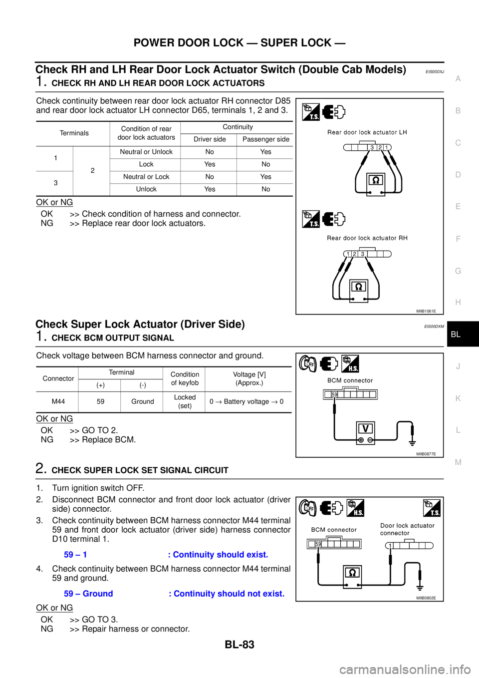
1.CHECK RH AND LH REAR DOOR LOCK ACTUATORS
Check continuity between rear door lock actuator RH connector D85
and rear door lock actuator LH connector D65, terminals 1, 2 and 3.
OK or NG
OK >> Check condition of harness and connector.
NG >> Replace rear door lock actuators.
Check Super Lock Actuator (Driver Side)EIS00DXM
1.CHECK BCM OUTPUT SIGNAL
Check voltage between BCM harness connector and ground.
OK or NG
OK >> GO TO 2.
NG >> Replace BCM.
2.CHECK SUPER LOCK SET SIGNAL CIRCUIT
1. Turn ignition switch OFF.
2. Disconnect BCM connector and front door lock actuator (driver
side) connector.
3. Check continuity between BCM harness connector M44 terminal
59 and front door lock actuator (driver side) harness connector
D10 terminal 1.
4. Check continuity between BCM harness connector M44 terminal
59 and ground.
OK or NG
OK >> GO TO 3.
NG >> Repair harness or connector.
Te r m i n a l sCondition of rear
door lock actuatorsContinuity
Driver side Passenger side
1
2Neutral or Unlock No Yes
Lock Yes No
3Neutral or Lock No Yes
Unlock Yes No
MIIB1061E
ConnectorTerminal
Condition
of keyfobVo l ta g e [V ]
(Approx.)
(+) (-)
M44 59 GroundLocked
(set)0®Battery voltage®0
MIIB0877E
59 – 1 : Continuity should exist.
59 – Ground : Continuity should not exist.
MIIB0802E
Page 685 of 3171
MULTI-REMOTE CONTROL SYSTEM
BL-101
C
D
E
F
G
H
J
K
L
MA
B
BL
Terminals and Reference Value for BCMEIS00DBI
*: Double cab modelsTerminalWire
ColorItem ConditionVoltage (V)
(Approx.)
3 Y Ignition switch ON or START Ignition switch ON or START Battery voltage
4 V Ignition switch ACC or ON Ignition switch ACC or ON Battery voltage
5RKeyswitchON (Key is inserted in key cylinder) Battery voltage
OFF (Key is removed from key cylinder) 0
12* L Rear door switch RHON (door open) 0
OFF (door closed) Battery voltage
14 LGFront door switch
(Passenger side)ON (door open) 0
OFF (door closed) Battery voltage
15 SBFront door switch
(Driver side)ON (door open) 0
OFF (door closed) Battery voltage
16* P Rear door switch LHON (door open) 0
OFF (door closed) Battery voltage
21 P CAN L — —
22 L CAN H — —
41 Y Power source (Fuse) — Battery voltage
55 B Ground — 0
57 W Power source (Fusible link) — Battery voltage
Page 689 of 3171
MULTI-REMOTE CONTROL SYSTEM
BL-105
C
D
E
F
G
H
J
K
L
MA
B
BL
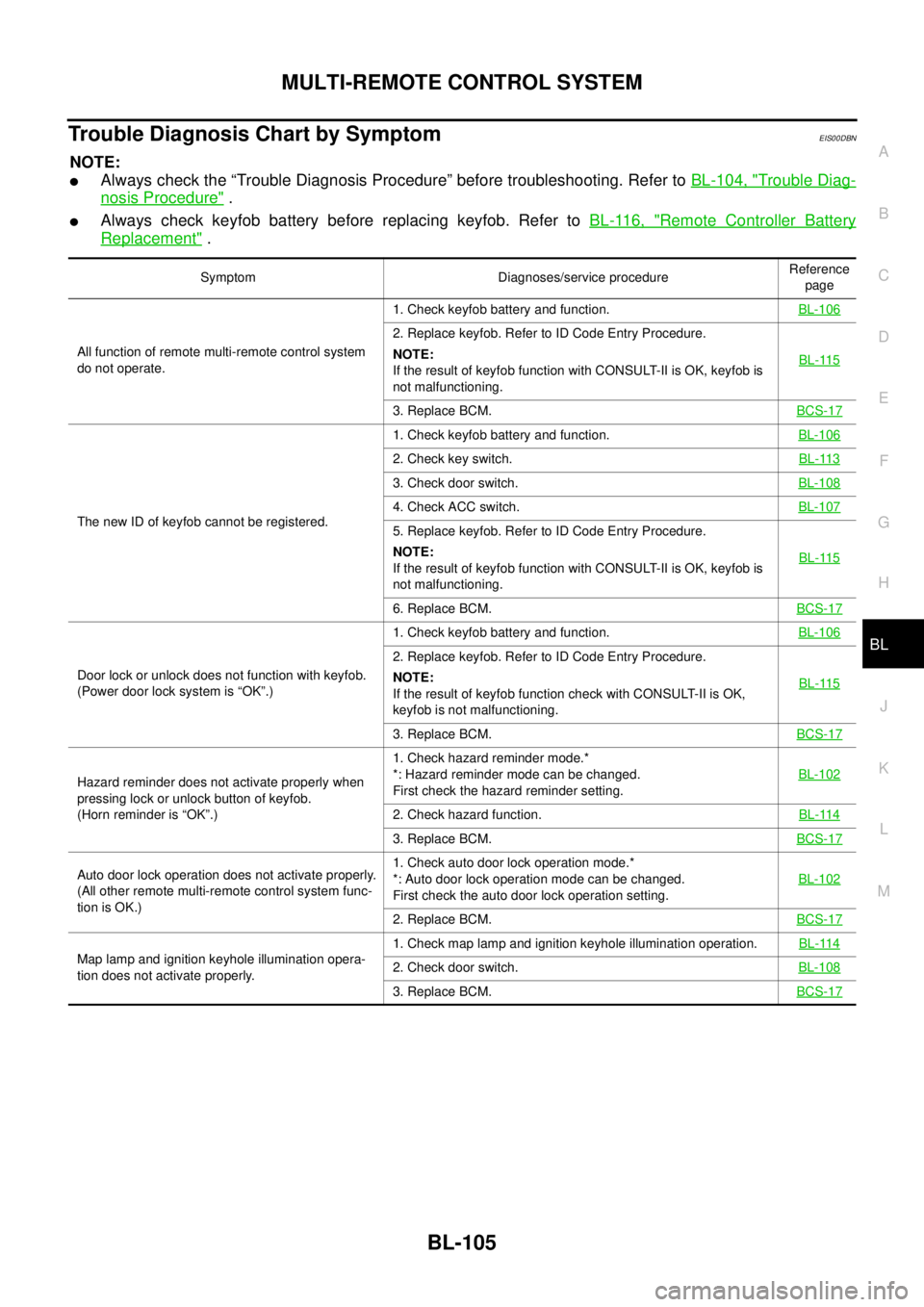
Trouble Diagnosis Chart by SymptomEIS00DBN
NOTE:
lAlways check the “Trouble Diagnosis Procedure” before troubleshooting. Refer toBL-104, "Trouble Diag-
nosis Procedure".
lAlways check keyfob battery before replacing keyfob. Refer toBL-116, "Remote Controller Battery
Replacement".
Symptom Diagnoses/service procedureReference
page
All function of remote multi-remote control system
do not operate.1. Check keyfob battery and function.BL-106
2. Replace keyfob. Refer to ID Code Entry Procedure.
NOTE:
If the result of keyfob function with CONSULT-II is OK, keyfob is
not malfunctioning.BL-115
3. Replace BCM.BCS-17
The new ID of keyfob cannot be registered.1. Check keyfob battery and function.BL-106
2. Check key switch.BL-113
3. Check door switch.BL-108
4. Check ACC switch.BL-107
5. Replace keyfob. Refer to ID Code Entry Procedure.
NOTE:
If the result of keyfob function with CONSULT-II is OK, keyfob is
not malfunctioning.BL-115
6. Replace BCM.BCS-17
Door lock or unlock does not function with keyfob.
(Power door lock system is “OK”.)1. Check keyfob battery and function.BL-106
2. Replace keyfob. Refer to ID Code Entry Procedure.
NOTE:
If the result of keyfob function check with CONSULT-II is OK,
keyfob is not malfunctioning.BL-115
3. Replace BCM.BCS-17
Hazard reminder does not activate properly when
pressing lock or unlock button of keyfob.
(Horn reminder is “OK”.)1. Check hazard reminder mode.*
*: Hazard reminder mode can be changed.
First check the hazard reminder setting.BL-102
2. Check hazard function.BL-114
3. Replace BCM.BCS-17
Auto door lock operation does not activate properly.
(All other remote multi-remote control system func-
tion is OK.)1. Check auto door lock operation mode.*
*: Auto door lock operation mode can be changed.
First check the auto door lock operation setting.BL-102
2. Replace BCM.BCS-17
Map lamp and ignition keyhole illumination opera-
tion does not activate properly.1. Check map lamp and ignition keyhole illumination operation.BL-1142. Check door switch.BL-108
3. Replace BCM.BCS-17