Page 423 of 3171

TROUBLE DIAGNOSIS
ATC-89
C
D
E
F
G
H
I
K
L
MA
B
AT C
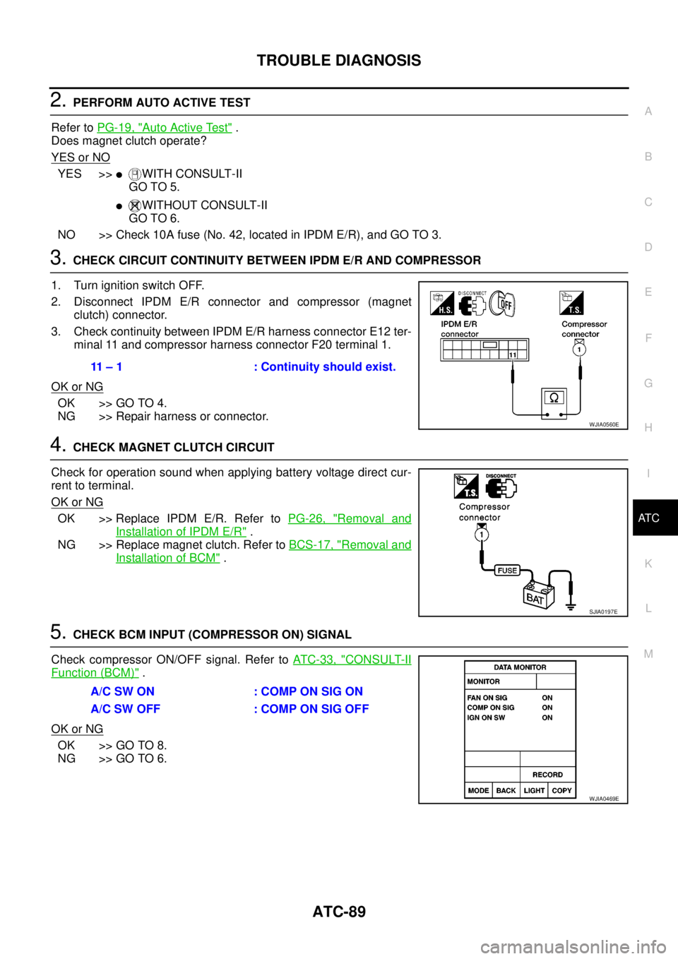
2.PERFORM AUTO ACTIVE TEST
Refer toPG-19, "
Auto Active Test".
Does magnet clutch operate?
YES or NO
YES >>lWITH CONSULT-II
GO TO 5.
lWITHOUT CONSULT-II
GO TO 6.
NO >> Check 10A fuse (No. 42, located in IPDM E/R), and GO TO 3.
3.CHECK CIRCUIT CONTINUITY BETWEEN IPDM E/R AND COMPRESSOR
1. Turn ignition switch OFF.
2. Disconnect IPDM E/R connector and compressor (magnet
clutch) connector.
3. Check continuity between IPDM E/R harness connector E12 ter-
minal 11 and compressor harness connector F20 terminal 1.
OK or NG
OK >> GO TO 4.
NG >> Repair harness or connector.
4.CHECK MAGNET CLUTCH CIRCUIT
Check for operation sound when applying battery voltage direct cur-
rent to terminal.
OK or NG
OK >> Replace IPDM E/R. Refer toPG-26, "Removal and
Installation of IPDM E/R".
NG >> Replace magnet clutch. Refer toBCS-17, "
Removal and
Installation of BCM".
5.CHECK BCM INPUT (COMPRESSOR ON) SIGNAL
Check compressor ON/OFF signal. Refer toAT C - 3 3 , "
CONSULT-II
Function (BCM)".
OK or NG
OK >> GO TO 8.
NG >> GO TO 6.
11 – 1 : Continuity should exist.
WJIA0560E
SJIA0197E
A/C SW ON : COMP ON SIG ON
A/CSWOFF :COMPONSIGOFF
WJIA0469E
Page 492 of 3171

AV-4
SYSTEM DESCRIPTION
SYSTEM DESCRIPTION
PFP:00000
System FunctionsEKS00Q5X
Refer to Owner's Manual for audio system operating instructions.
AUDIO
Speed Sensitive Volume (6CD Player Type)
Volume level of this system gone up and down automatically in proportion to the vehicle speed. And the con-
trol level can be selected by the customer.
NATS AUDIO LINK (WITHOUT NAVIGATION SYSTEM)
Description
The link with the NATS IMMU implies that the audio unit can basically only be operated if connected to the
matching NATS IMMU to which the audio unit was initially fitted on the production line.
Since radio operation is impossible after the link with the NATS is disrupted theft of the audio unit is basically
useless since special equipment is required to reset the audio unit.
Initialization Process for Audio Units That Are Linked to The NATS IMMU
New audio units will be delivered to the factories in the “NEW” state, i.e. ready to be linked with the vehicle's
NATS. When the audio unit in “NEW” state is first switched on at the factory, it will start up communication with
the vehicle's immobilizer control unit (IMMU) and send a code (the “audio unit Code”) to the IMMU. The IMMU
will then store this code, which is unique to each audio unit, in its (permanent) memory.
Upon receipt of the code by the IMMU, the NATS will confirm correct receipt of the audio unit code to the audio
unit. Hereafter, the audio unit will operate as normal.
During the initialization process, “NEW” is displayed on the audio unit display. Normally though, communica-
tion between audio unit and IMMU takes such a short time (300 ms) that the audio unit seems to switch on
directly without showing “NEW” on its display.
Normal Operation
Each time the audio unit is switched on afterwards, the audio unit code will be verified between the audio unit
and the NATS before the audio unit becomes operational. During the code verification process, “WAIT” is
shown on the audio unit display. Again, the communication takes such a short time (300 ms) that the audio
unit seems to switch on directly without showing “WAIT” on its display.
When The Radio Is Locked
In case of a audio unit being linked with the vehicle's NATS (immobilizer system), disconnection of the link
between the audio unit and the IMMU will cause the audio unit to switch into the lock (“SECURE”) mode in
which the audio unit is fully inoperative. Hence, repair of the audio unit is basically impossible, unless the
audio unit is reset to the “NEW” state for which special decoding equipment is required.
Clarion has provided their authorized service representatives with so called “decoder boxes” which can bring
the audio unit back to the “NEW” state, enabling the audio unit to be switched on after which repair can be per-
formed. Subsequently, when the repaired audio unit is delivered to the final user again, it will be in the “NEW”
state to enable re-linking the audio unit to the vehicle's immobilizer system. As a result of the above, repair of
the audio unit can only be done by an authorized Clarion representative (when the owner of the vehicle
requests repair and can show personal identification).
Service Procedure
Item Service procedure Description
Battery disconnection No additional action required. –
Radio needs repair Repair needs to be done by authorized
representative of radio manufacturer since
radio cannot be operated unless it is reset
to NEW state, using special decoding
equipment.–
Replacement of radio by new part No additional action required. Radio is delivered in NEW state.
Transferring radio to another vehicle/
replacement of radio by an “old” partRadio needs to be reset to NEW state by
authorized representative of radio manu-
facturer.–
Replacement of IMMU Radio needs to be reset to NEW state by
authorized representative of Clarion.After switching on the radio, it will display
“SECURE” after 1 minute.
Page 522 of 3171
AV-34
TERMINALS AND REFERENCE VALUE FOR CONTROL UNIT
TERMINALS AND REFERENCE VALUE FOR CONTROL UNIT
PFP:00000
Audio Unit (1CD Player Type)EKS00Q6B
Te r m i n a l
(Wire color)
ItemSignal
input/
outputCondition
Reference value
+-Ignition
switchOperation
2
(O)Ground Illumination signal Input ONLighting switch is ON. Approx. 12 V
Lighting switch is OFF. Approx. 0 V
3
(Y)Ground Battery power supply Input ON – Battery voltage
4
(Y)–TELmute – – – –
6
(V)Ground ACC power supply Input ACC – Battery voltage
7
(BR)5
(L)Audio signal front LH Output ON Sound output
8
(W)GroundVehicle speed signal
(2-pulse)Input ONWhen vehicle speed is
approx. 40 km/h (25
MPH).
9
(L)10
(V)Audio signal rear LH Output ON Sound output
12
(SB)– Immobilizer – – – –
13
(LG)11
(V)Audio signal front RH Output ON Sound output
15
(GR)16
(V)Audio signal rear RH Output ON Sound output
19
(W)–TELin(-) – – – –
SKIB1990E
ELF1080D
SKIB1990E
SKIB1990E
SKIB1990E
Page 523 of 3171

TERMINALS AND REFERENCE VALUE FOR CONTROL UNIT
AV-35
C
D
E
F
G
H
I
J
L
MA
B
AV
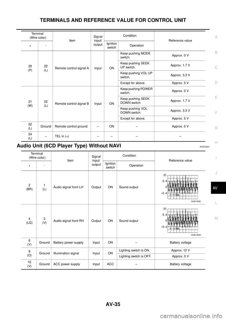
Audio Unit (6CD Player Type) Without NAVIEKS00Q6C
20
(P)22
(L)Remote control signal A Input ONKeep pushing MODE
switch.Approx. 0 V
Keep pushing SEEK
UP switch.Approx. 1.7 V
Keep pushing VOL UP
switch.Approx. 3.3 V
Except for above. Approx. 5 V
21
(W)22
(L)Remote control signal B Input ONKeep pushing POWER
switch.Approx. 0 V
Keep pushing SEEK
DOWN switch.Approx. 1.7 V
Keep pushing VOL
DOWN switch.Approx. 3.3 V
Except for above. Approx. 5 V
22
(L)Ground Remote control ground – ON – Approx. 0 V
24
(L)–TELin(+) – – – – Terminal
(Wire color)
ItemSignal
input/
outputCondition
Reference value
+-Ignition
switchOperation
Terminal
(Wire color)
ItemSignal
input/
outputCondition
Reference value
+-Ignition
switchOperation
2
(BR)1
(L)Audio signal front LH Output ON Sound output
4
(LG)3
(V)Audio signal front RH Output ON Sound output
6
(Y)Ground Battery power supply Input ON – Battery voltage
8
(O)Ground Illumination signal Input ONLighting switch is ON. Approx. 12 V
Lighting switch is OFF. Approx. 0 V
10
(V)Ground ACC power supply Input ACC – Battery voltage
SKIB1990E
SKIB1990E
Page 525 of 3171

TERMINALS AND REFERENCE VALUE FOR CONTROL UNIT
AV-37
C
D
E
F
G
H
I
J
L
MA
B
AV
Audio Unit (With NAVI)EKS00Q6D
Terminal
(Wire color)
ItemSignal
input/
outputCondition
Reference value
+-Ignition
switchOperation
3
(Y)–Communication
signal (H)Input/
output–– –
4
(R)–Communication
signal (L)Input/
output–– –
10
(W)11
(O)TEL voice signal Input ON TEL voice output
12
(O)13
(W)Voice guidance signal Input ON Voice guidance output
17 Ground Shield (TEL voice) – ON – Approx. 0 V
18 Ground Shield (Guide voice) – ON – Approx. 0 V
22
(BR)23
(L)Audio signal front LH Output ON Sound output
24
(L)25
(V)Audio signal rear LH Output ON Sound output
26
(P)35
(L)Remote control signal A Input ONKeep pushing SOURCE
switch.approx. 0 V
Keep pushing MENU
UP switch.Approx. 1.2 V
Keep pushing MENU
DOWN switch.Approx. 2.5 V
Keep pushing ENTER
switch.Approx. 3.7 V
Except for above. Approx. 5 V
27
(V)Ground ACC power supply Input ACC – Battery voltage
28
(B)GroundIllumination control sig-
nalInput ONIllumination control
switch is operated by
lighting switch in ON
positionChanges between approx. 0 V
and approx. 12 V
SKIB1990E
SKIB1990E
SKIB1990E
SKIB1990E
Page 526 of 3171

AV-38
TERMINALS AND REFERENCE VALUE FOR CONTROL UNIT
NAVI Control Unit
EKS00Q6E
29
(O)Ground Illumination signal Input ONLighting switch is ON. Approx. 12 V
Lighting switch is OFF. Approx. 0 V
31
(LG)32
(V)Audio signal front RH Output ON Sound output
33
(GR)34
(V)Audio signal rear RH Output ON Sound output
36
(W)35
(L)Remote control signal B Input ONKeep pushing VOL
DOWN switch.Approx. 0 V
Keep pushing VOL UP
switch.Approx. 1.2 V
Keep pushing TEL, PTT
switch.Approx. 2.5 V
Keep pushing BACK
switch.Approx. 3.7 V
Except for above. Approx. 5 V
39
(Y)Ground Battery power supply Input ON – Battery voltage Terminal
(Wire color)
ItemSignal
input/
outputCondition
Reference value
+-Ignition
switchOperation
SKIB1990E
SKIB1990E
Terminal
(Wire color)
ItemSignal
input/
outputCondition
Reference value
+-Ignition
switchOperation
1
(B)Ground Ground – ON – Approx. 0 V
2
(Y)Ground Battery power supply Input ON – Battery voltage
5
(V)Ground ACC power supply Input ACC – Battery voltage
6
(B)Ground MIC. power supply Output ON – Approx. 5 V
7 Ground Shield (MIC.) – ON – Approx. 0 V
8
(W)Ground MIC. signal Input ON Sounds
9 Ground Shield (TEL voice) – ON – Approx. 0 V
PKIB5037J
Page 528 of 3171

AV-40
TERMINALS AND REFERENCE VALUE FOR CONTROL UNIT
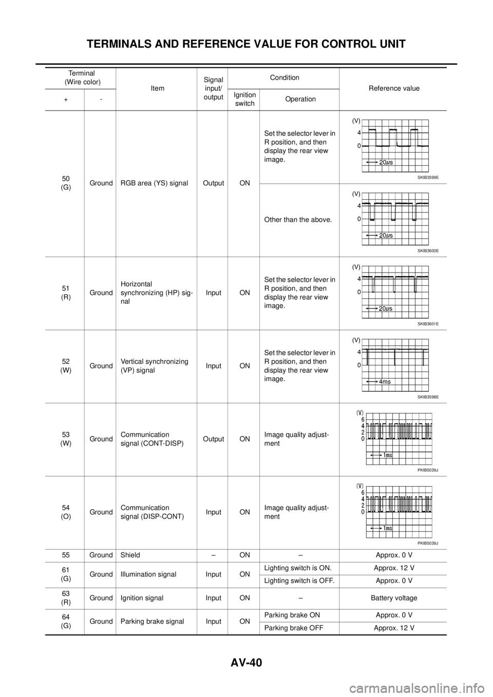
50
(G)Ground RGB area (YS) signal Output ONSet the selector lever in
R position, and then
display the rear view
image.
Other than the above.
51
(R)GroundHorizontal
synchronizing (HP) sig-
nalInput ONSet the selector lever in
R position, and then
display the rear view
image.
52
(W)GroundVertical synchronizing
(VP) signalInput ONSet the selector lever in
R position, and then
display the rear view
image.
53
(W)GroundCommunication
signal (CONT-DISP)Output ONImage quality adjust-
ment
54
(O)GroundCommunication
signal (DISP-CONT)Input ONImage quality adjust-
ment
55 Ground Shield – ON – Approx. 0 V
61
(G)Ground Illumination signal Input ONLighting switch is ON. Approx. 12 V
Lighting switch is OFF. Approx. 0 V
63
(R)Ground Ignition signal Input ON – Battery voltage
64
(G)Ground Parking brake signal Input ONParking brake ON Approx. 0 V
Parking brake OFF Approx. 12 V Terminal
(Wire color)
ItemSignal
input/
outputCondition
Reference value
+-Ignition
switchOperationSKIB3599E
SKIB3600E
SKIB3601E
SKIB3598E
PKIB5039J
PKIB5039J
Page 531 of 3171
TERMINALS AND REFERENCE VALUE FOR CONTROL UNIT
AV-43
C
D
E
F
G
H
I
J
L
MA
B
AV
19
(W)GroundCommunication
signal (CONT-DISP)Input ON Image quality adjustment
20
(V)Ground ACC power supply Input ACC – Battery voltage
21
(Y)Ground Battery power supply Input ON – Battery voltage
23
(B)Ground Ground – ON – Approx. 0 V Terminal
(Wire color)
ItemSignal
input/
outputCondition
Reference value
+-Ignition
switchOperation
PKIB5039J