Page 180 of 3171
AT-172
OVERDRIVE CONTROL SWITCH
OVERDRIVE CONTROL SWITCH
PFP:25130
CONSULT-II Reference ValueECS00HQY
Diagnostic ProcedureECS00HQZ
1.CHECK CAN COMMUNICATION LINE
Perform the self-diagnosis. Refer toAT-80, "
SELF-DIAGNOSTIC RESULT MODE".
Is any malfunction in the CAN communication indicated in the results?
YES >> Check CAN communication line. Refer toAT-91, "DTC U1000 CAN COMMUNICATION LINE".
NO >> GO TO 2.
2.CHECK OVERDRIVE CONTOROL SWITCH CIRCUIT
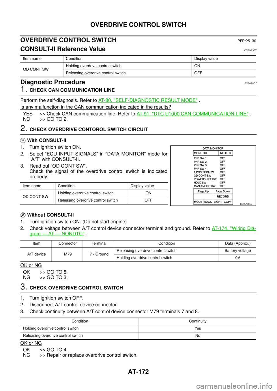
With CONSULT-II
1. Turn ignition switch ON.
2. Select “ECU INPUT SIGNALS” in “DATA MONITOR” mode for
“A/T” with CONSULT-II.
3. Read out “OD CONT SW”.
Check the signal of the overdrive control switch is indicated
properly.
Without CONSULT-II
1. Turn ignition switch ON. (Do not start engine)
2. Check voltage between A/T control device connector terminal and ground. Refer toAT- 1 7 4 , "
Wiring Dia-
gram—AT—NONDTC".
OK or NG
OK >> GO TO 5.
NG >> GO TO 3.
3.CHECK OVERDRIVE CONTROL SWITCH
1. Turn ignition switch OFF.
2. Disconnect A/T control device connector.
3. Check continuity between A/T control device connector M79 terminals 7 and 8.
OK or NG
OK >> GO TO 4.
NG >> Repair or replace overdrive control switch.
Item name Condition Display value
OD CONT SWHolding overdrive control switch ON
Releasing overdrive control switch OFF
Item name Condition Display value
OD CONT SWHolding overdrive control switch ON
Releasing overdrive control switch OFF
SCIA7305E
Item Connector Terminal Condition Data (Approx.)
A/T device M79 7 - GroundReleasing overdrive control switch Battery voltage
Holding overdrive control switch 0V
Condition Continuity
Holding overdrive control switch Yes
Releasing overdrive control switch No
Page 185 of 3171
TROUBLE DIAGNOSIS FOR SYMPTOMS
AT-177
D
E
F
G
H
I
J
K
L
MA
B
AT
Data are reference value and are measured between each terminal and ground.
OD OFF Indicator Lamp Does Not Come OnECS00G2B
SYMPTOM:
OD OFF indicator lamp does not come on for about 2 seconds when turning ignition switch ON.
DIAGNOSTIC PROCEDURE
1.CHECK CAN COMMUNICATION LINE
Perform self-diagnosis. Refer toAT-80, "
SELF-DIAGNOSTIC RESULT MODE",AT-89, "Diagnostic Procedure
Without CONSULT-II".
Is a malfunction in the CAN communication indicated in the results?
YES >> Check CAN communication line. Refer toAT-91, "DTC U1000 CAN COMMUNICATION LINE".
NO >> GO TO 2.
2.CHECK OD OFF INDICATOR LAMP CIRCUIT
Check combination meter. Refer toDI-4, "
COMBINATION METERS".
OK or NG
OK >> GO TO 3
NG >> Repair or replace damaged parts.
3.CHECK TCM POWER SUPPLY AND GROUND CIRCUIT
Check TCM power supply and ground circuit. Refer toAT- 1 6 4 , "
MAIN POWER SUPPLY AND GROUND CIR-
CUIT".
OK or NG
OK >>INSPECTION END
NG >> Repair or replace damaged parts.
Engine Cannot Be Started in “P” or “N” PositionECS00G2C
SYMPTOM:
lEngine cannot be started with selector lever in “P” or “N” position.
lEngine can be started with selector lever in “R”, “D”, “3”, “2” or “1” position.
DIAGNOSTIC PROCEDURE
1.CHECK SELF-DIAGNOSIS RESULTS
Perform self-diagnosis. Refer toAT-80, "
SELF-DIAGNOSTIC RESULT MODE",AT-89, "Diagnostic Procedure
Without CONSULT-II".
Do the self-diagnosis results indicate PNP switch?
YES >> Check malfunctioning system. Refer toAT-99, "DTC P0705 PARK/NEUTRAL POSITION
SWITCH".
NO >> GO TO 2.
TerminalWire
colorItem Condition Data (Approx.)
3 L CAN-H – –
4GRK-line (CONSULT-
II signal)The terminal is connected to the data link connector for CONSULT-II. –
7LGBack-up lamp
relaySelector lever in “R” position. 0V
Selector lever in other positions. Battery voltage
8 P CAN-L – –
9BRStarterrelaySelector lever in “N” or “P” position. Battery voltage
Selector lever in other positions. 0V
Page 222 of 3171

AT-214
A/T SHIFT LOCK SYSTEM
Diagnostic Procedure
ECS00G32
SYMPTOM 1:
lSelector lever cannot be moved from “P” position with key in ON position and brake pedal
applied.
lSelector lever can be moved from “P” position with key in ON position and brake pedal released.
lSelector lever can be moved from “P” position when key is removed from key cylinder.
SYMPTOM 2:
lIgnition key cannot be removed when selector lever is set to “P” position.
lIgnition key can be removed when selector lever is set to any position except “P” position.
1.CHECK KEY INTERLOCK CABLE
Check key interlock cable for damage.
OK or NG
OK >> GO TO 2.
NG >> Repair or replace key interlock cable. Refer toAT- 2 1 6 , "
Removal and Installation".
2.CHECK SELECTOR LEVER POSITION
Check selector lever position for damage. Refer toAT- 2 11 , "
Checking of A/T Position"
OK or NG
OK >> GO TO 3.
NG >> Adjust control cable. Refer toAT- 2 11 , "
Adjustment of A/T Position".
3.CHECK SHIFT LOCK SOLENOID AND PARK POSITION SWITCH
1. Connect A/T device harness connector.
2. Turn ignition switch ON. (Do not start engine.)
3. Selector lever is set in “P” position.
4. Check operation.
OK or NG
OK >>INSPECTION END
NG >> GO TO 4.
4.CHECK POWER SOURCE
1. Turn ignition switch ON. (Do not start engine.)
2. Check voltage between A/T device harness connector M79 ter-
minal 1 and ground.
OK or NG
OK >> GO TO 7.
NG >> GO TO 5.
Condition Brake pedal Operation
When ignition switch is turned to ON and selector lever is
set in “P” position.Depressed Yes
Released No
Condition Brake pedal Data (Approx.)
When ignition switch is turned to ON.Depressed Battery voltage
Released 0V
SCIA2122E
Page 227 of 3171
ON-VEHICLE SERVICE
AT-219
D
E
F
G
H
I
J
K
L
MA
B
AT
CONTROL VALVE WITH TCM REMOVAL AND INSTALLATION
Removal
1. Disconnect the battery cable from the negative terminal.
2. Remove under cover.
3. Drain ATF through drain hole.
4. Remove control cable from A/T assembly. Refer toAT- 2 1 0 , "
COMPONENTS".
5. Disconnect A/T assembly harness connector.
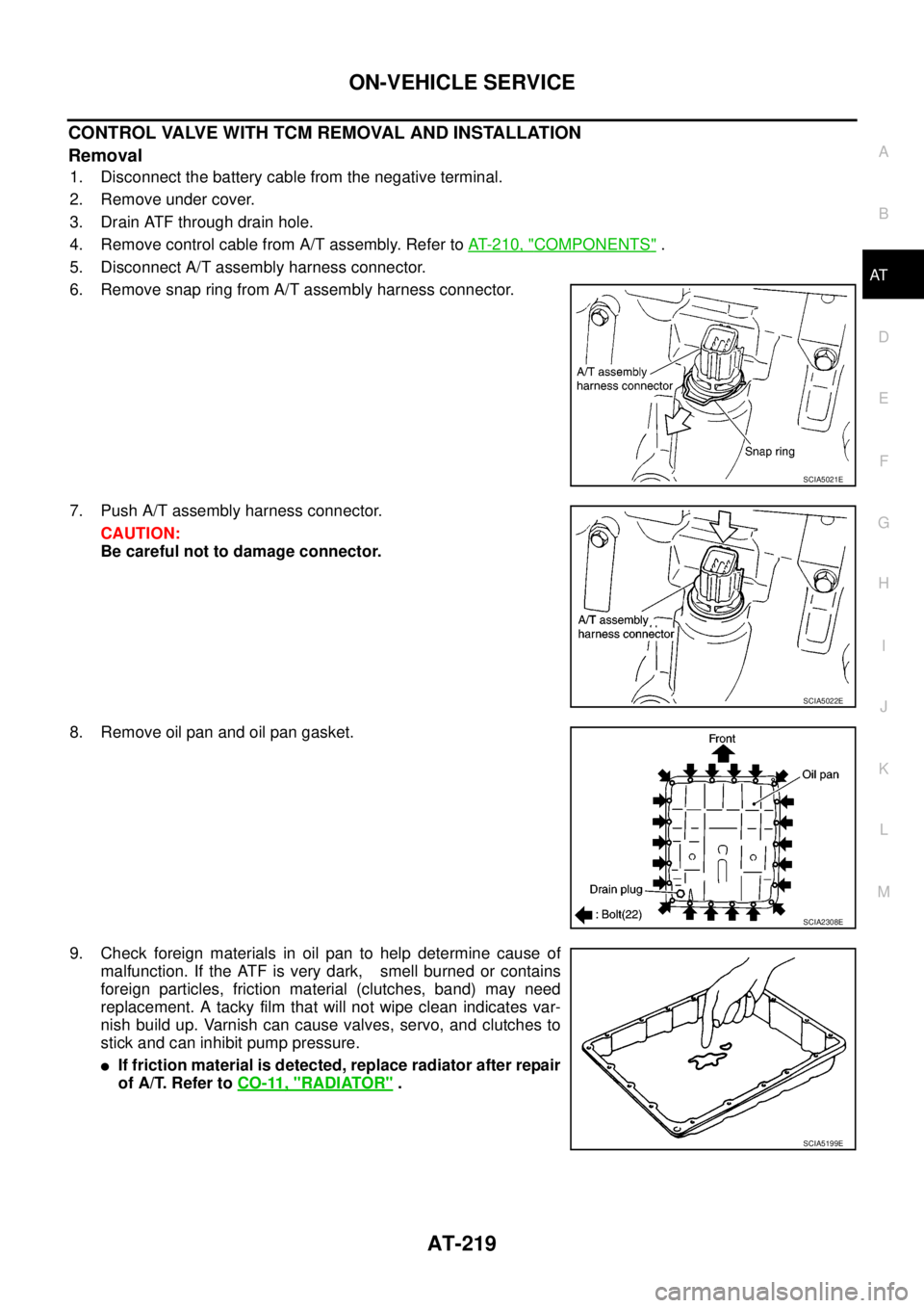
6. Remove snap ring from A/T assembly harness connector.
7. Push A/T assembly harness connector.
CAUTION:
Be careful not to damage connector.
8. Remove oil pan and oil pan gasket.
9. Check foreign materials in oil pan to help determine cause of
malfunction. If the ATF is very dark, smell burned or contains
foreign particles, friction material (clutches, band) may need
replacement. A tacky film that will not wipe clean indicates var-
nish build up. Varnish can cause valves, servo, and clutches to
stick and can inhibit pump pressure.
lIf friction material is detected, replace radiator after repair
of A/T. Refer toCO-11, "
RADIATOR".
SCIA5021E
SCIA5022E
SCIA2308E
SCIA5199E
Page 234 of 3171
AT-226
ON-VEHICLE SERVICE
15. Install oil pan to transmission case.
a. Install oil pan gasket to oil pan.
CAUTION:
lDo not reuse oil pan gasket.
lInstall it in the direction to align hole positions.
lCompletely remove all moisture, oil and old gasket, etc. from oil pan gasket mounting surface.
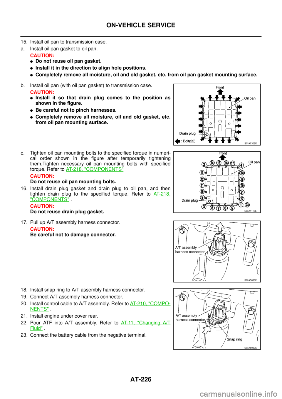
b. Install oil pan (with oil pan gasket) to transmission case.
CAUTION:
lInstall it so that drain plug comes to the position as
shown in the figure.
lBe careful not to pinch harnesses.
lCompletely remove all moisture, oil and old gasket, etc.
from oil pan mounting surface.
c. Tighten oil pan mounting bolts to the specified torque in numeri-
cal order shown in the figure after temporarily tightening
them.Tighten necessary oil pan mounting bolts with specified
torque. Refer toAT- 2 1 8 , "
COMPONENTS"
CAUTION:
Do not reuse oil pan mounting bolts.
16. Install drain plug gasket and drain plug to oil pan, and then
tighten drain plug to the specified torque. Refer toAT-218,
"COMPONENTS".
CAUTION:
Do not reuse drain plug gasket.
17. Pull up A/T assembly harness connector.
CAUTION:
Be careful not to damage connector.
18. Install snap ring to A/T assembly harness connector.
19. Connect A/T assembly harness connector.
20. Install control cable to A/T assembly. Refer toAT- 2 1 0 , "
COMPO-
NENTS".
21. Install engine under cover rear.
22. Pour ATF into A/T assembly. Refer toAT-11, "
Changing A/T
Fluid".
23. Connect the battery cable from the negative terminal.
SCIA2308E
SCIA4113E
SCIA5038E
SCIA5039E
Page 235 of 3171
ON-VEHICLE SERVICE
AT-227
D
E
F
G
H
I
J
K
L
MA
B
AT
A/T FLUID TEMPERATURE SENSOR 2 REMOVAL AND INSTALLATION
Removal
1. Disconnect the battery cable from the negative terminal.
2. Remove under cover.
3. Drain ATF through drain hole.
4. Remove oil pan and oil pan gasket.
5. Check foreign materials in oil pan to help determine cause of
malfunction. If the ATF is very dark, smell burned or contains
foreign particles, friction material (clutches, band) may need
replacement. A tacky film that will not wipe clean indicates var-
nish build up. Varnish can cause valves, servo, and clutches to
stick and can inhibit pump pressure.
lIf friction material is detected, replace radiator after repair
of A/T. Refer toCO-11, "
RADIATOR".
6. Disconnect A/T fluid temperature sensor 2 connector.
CAUTION:
Be careful not to damage connector.
7. Straighten terminal clip to free A/T fluid temperature sensor 2
harness.
SCIA2308E
SCIA5199E
SCIA5023E
SCIA5146E
Page 237 of 3171
ON-VEHICLE SERVICE
AT-229
D
E
F
G
H
I
J
K
L
MA
B
AT
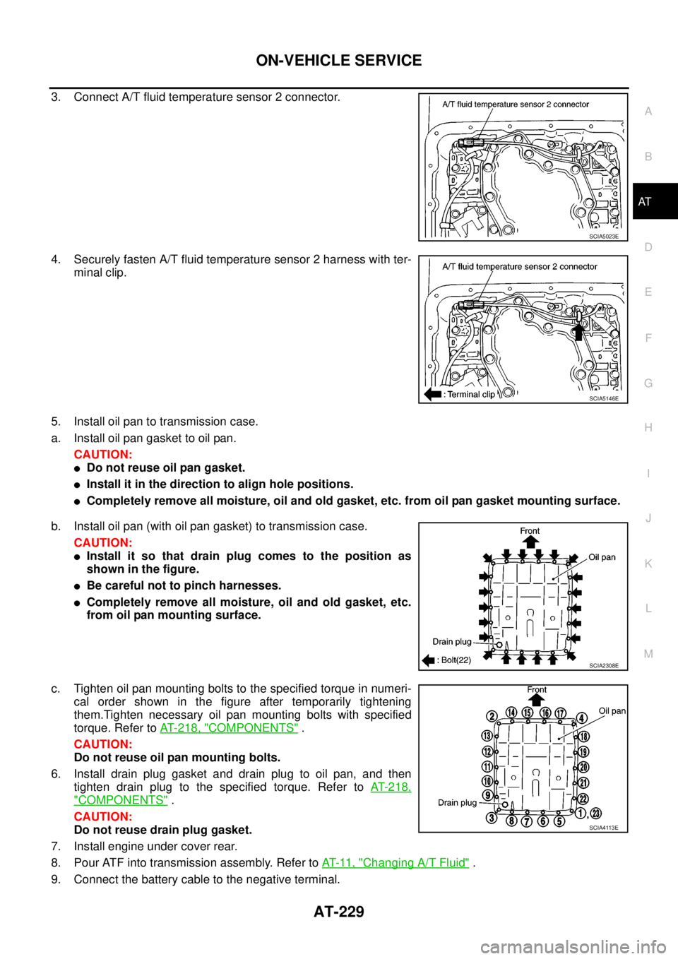
3. Connect A/T fluid temperature sensor 2 connector.
4. Securely fasten A/T fluid temperature sensor 2 harness with ter-
minal clip.
5. Install oil pan to transmission case.
a. Install oil pan gasket to oil pan.
CAUTION:
lDo not reuse oil pan gasket.
lInstall it in the direction to align hole positions.
lCompletely remove all moisture, oil and old gasket, etc. from oil pan gasket mounting surface.
b. Install oil pan (with oil pan gasket) to transmission case.
CAUTION:
lInstall it so that drain plug comes to the position as
shown in the figure.
lBe careful not to pinch harnesses.
lCompletely remove all moisture, oil and old gasket, etc.
from oil pan mounting surface.
c. Tighten oil pan mounting bolts to the specified torque in numeri-
cal order shown in the figure after temporarily tightening
them.Tighten necessary oil pan mounting bolts with specified
torque. Refer toAT- 2 1 8 , "
COMPONENTS".
CAUTION:
Do not reuse oil pan mounting bolts.
6. Install drain plug gasket and drain plug to oil pan, and then
tighten drain plug to the specified torque. Refer toAT-218,
"COMPONENTS".
CAUTION:
Do not reuse drain plug gasket.
7. Install engine under cover rear.
8. Pour ATF into transmission assembly. Refer toAT-11, "
Changing A/T Fluid".
9. Connect the battery cable to the negative terminal.
SCIA5023E
SCIA5146E
SCIA2308E
SCIA4113E
Page 246 of 3171
AT-238
ON-VEHICLE SERVICE
Revolution Sensor Components (2WD Models Only)
ECS00GVN
REMOVAL AND INSTALLATION
Components
Removal
1. Disconnect the battery cable from the negative terminal.
2. Drain ATF through drain hole.
3. Remove rear propeller shaft. Refer toPR-8, "
Removal and Installation".
4. Remove control cable from A/T assembly. Refer toAT- 2 1 0 , "
Control Cable Removal and Installation".
1. Rear extension 2. A/T 3. Revolution sensor
4. Oil pan gasket 5. Oil pan 6. Oil pan mounting bolt
7. Drain plug gasket 8. Drain plug 9. Self-sealing bolt
Refer to GI section to make sure icons (symbol marks) in the figure. Refer toGI-10, "
Components".
However, refer to the following symbols for others.
*:Apply Anaerobic Liquid Gasket (Loctite 518) or equivalent.
SCIA7075E