Page 250 of 3171
AT-242
ON-VEHICLE SERVICE
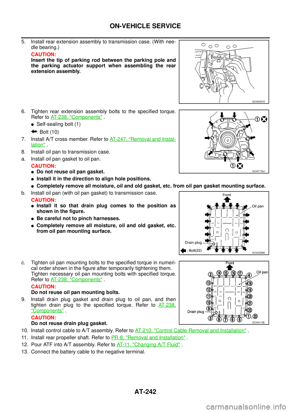
5. Install rear extension assembly to transmission case. (With nee-
dle bearing.)
CAUTION:
Insert the tip of parking rod between the parking pole and
the parking actuator support when assembling the rear
extension assembly.
6. Tighten rear extension assembly bolts to the specified torque.
Refer toAT- 2 3 8 , "
Components".
lSelf-sealing bolt (1)
:Bolt(10)
7. Install A/T cross member. Refer toAT- 2 4 7 , "
Removal and Instal-
lation".
8. Install oil pan to transmission case.
a. Install oil pan gasket to oil pan.
CAUTION:
lDo not reuse oil pan gasket.
lInstall it in the direction to align hole positions.
lCompletely remove all moisture, oil and old gasket, etc. from oil pan gasket mounting surface.
b. Install oil pan (with oil pan gasket) to transmission case.
CAUTION:
lInstall it so that drain plug comes to the position as
shown in the figure.
lBe careful not to pinch harnesses.
lCompletely remove all moisture, oil and old gasket, etc.
from oil pan mounting surface.
c. Tighten oil pan mounting bolts to the specified torque in numeri-
cal order shown in the figure after temporarily tightening them.
Tighten necessary oil pan mounting bolts with specified torque.
Refer toAT- 2 3 8 , "
Components".
CAUTION:
Do not reuse oil pan mounting bolts.
9. Install drain plug gasket and drain plug to oil pan, and then
tighten drain plug to the specified torque. Refer toAT-238,
"Components".
CAUTION:
Do not reuse drain plug gasket.
10. Install control cable to A/T assembly. Refer toAT- 2 1 0 , "
Control Cable Removal and Installation".
11. Install rear propeller shaft. Refer toPR-8, "
Removal and Installation".
12. Pour ATF into A/T assembly. Refer toAT-11, "
Changing A/T Fluid".
13. Connect the battery cable to the negative terminal.
SCIA3431E
SCIA7176J
SCIA2308E
SCIA4113E
Page 256 of 3171
AT-248
TRANSMISSION ASSEMBLY
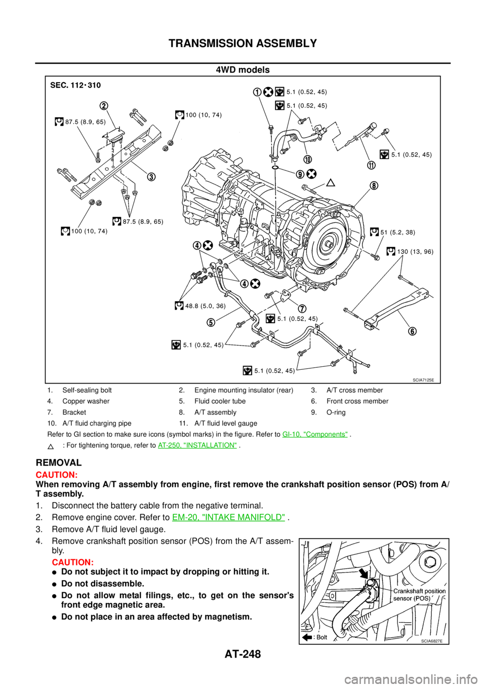
4WD models
REMOVAL
CAUTION:
When removing A/T assembly from engine, first remove the crankshaft position sensor (POS) from A/
T assembly.
1. Disconnect the battery cable from the negative terminal.
2. Remove engine cover. Refer toEM-20, "
INTAKE MANIFOLD".
3. Remove A/T fluid level gauge.
4. Remove crankshaft position sensor (POS) from the A/T assem-
bly.
CAUTION:
lDo not subject it to impact by dropping or hitting it.
lDo not disassemble.
lDo not allow metal filings, etc., to get on the sensor's
front edge magnetic area.
lDo not place in an area affected by magnetism.
SCIA7125E
1. Self-sealing bolt 2. Engine mounting insulator (rear) 3. A/T cross member
4. Copper washer 5. Fluid cooler tube 6. Front cross member
7. Bracket 8. A/T assembly 9. O-ring
10. A/T fluid charging pipe 11. A/T fluid level gauge
Refer to GI section to make sure icons (symbol marks) in the figure. Refer toGI-10, "
Components".
: For tightening torque, refer toAT-250, "
INSTALLATION".
SCIA6827E
Page 351 of 3171
PREPARATION
ATC-17
C
D
E
F
G
H
I
K
L
MA
B
AT C
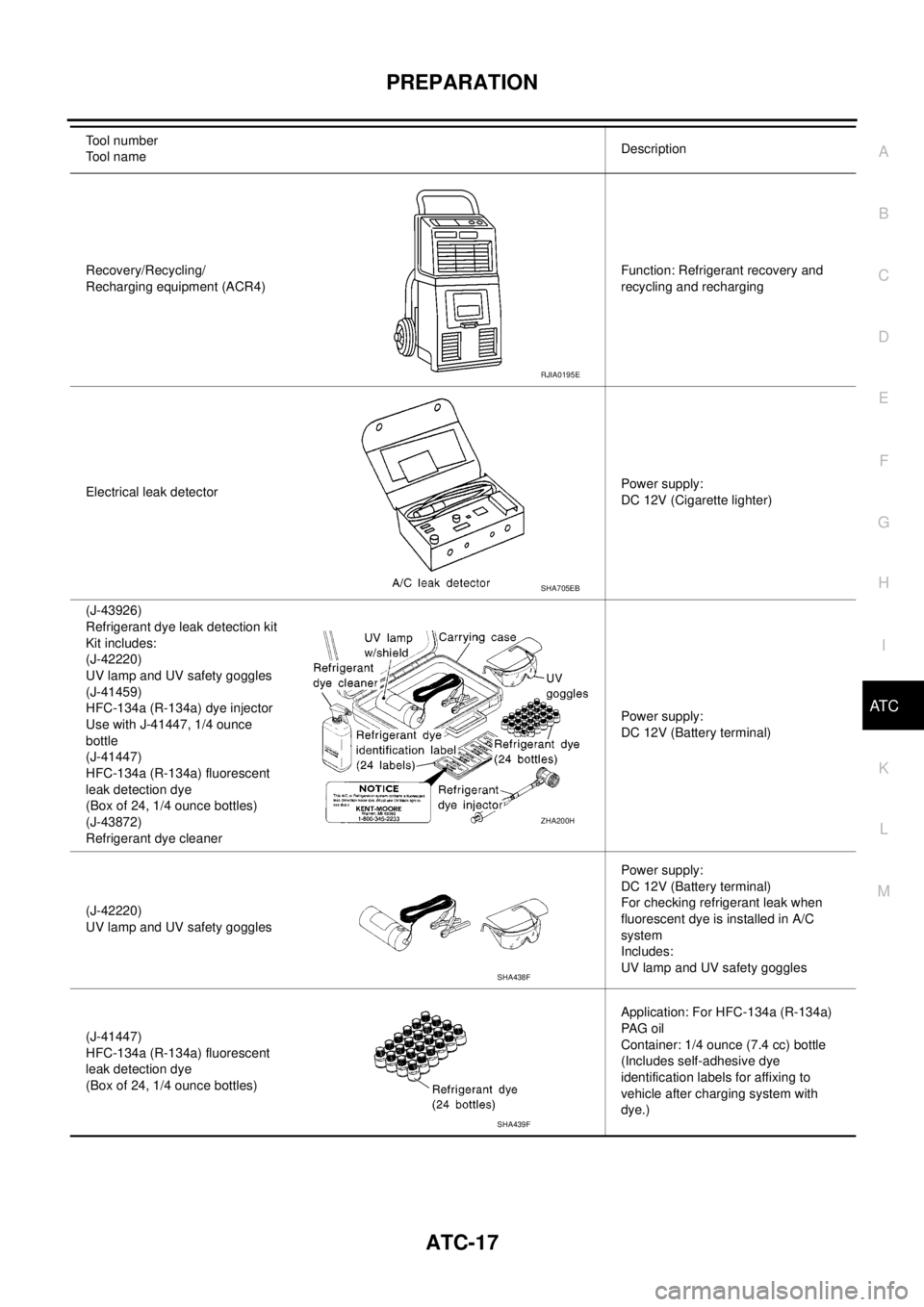
Recovery/Recycling/
Recharging equipment (ACR4)Function: Refrigerant recovery and
recycling and recharging
Electrical leak detectorPower supply:
DC 12V (Cigarette lighter)
(J-43926)
Refrigerant dye leak detection kit
Kit includes:
(J-42220)
UV lamp and UV safety goggles
(J-41459)
HFC-134a (R-134a) dye injector
Use with J-41447, 1/4 ounce
bottle
(J-41447)
HFC-134a (R-134a) fluorescent
leak detection dye
(Box of 24, 1/4 ounce bottles)
(J-43872)
Refrigerant dye cleanerPower supply:
DC 12V (Battery terminal)
(J-42220)
UV lamp and UV safety gogglesPower supply:
DC 12V (Battery terminal)
For checking refrigerant leak when
fluorescent dye is installed in A/C
system
Includes:
UV lamp and UV safety goggles
(J-41447)
HFC-134a (R-134a) fluorescent
leak detection dye
(Box of 24, 1/4 ounce bottles)Application: For HFC-134a (R-134a)
PA G o i l
Container: 1/4 ounce (7.4 cc) bottle
(Includes self-adhesive dye
identification labels for affixing to
vehicle after charging system with
dye.) Tool number
Tool nameDescription
RJIA0195E
SHA705EB
ZHA200H
SHA438F
SHA439F
Page 387 of 3171
TROUBLE DIAGNOSIS
ATC-53
C
D
E
F
G
H
I
K
L
MA
B
AT C
Front Air Control Terminals and Reference ValueEJS006BF
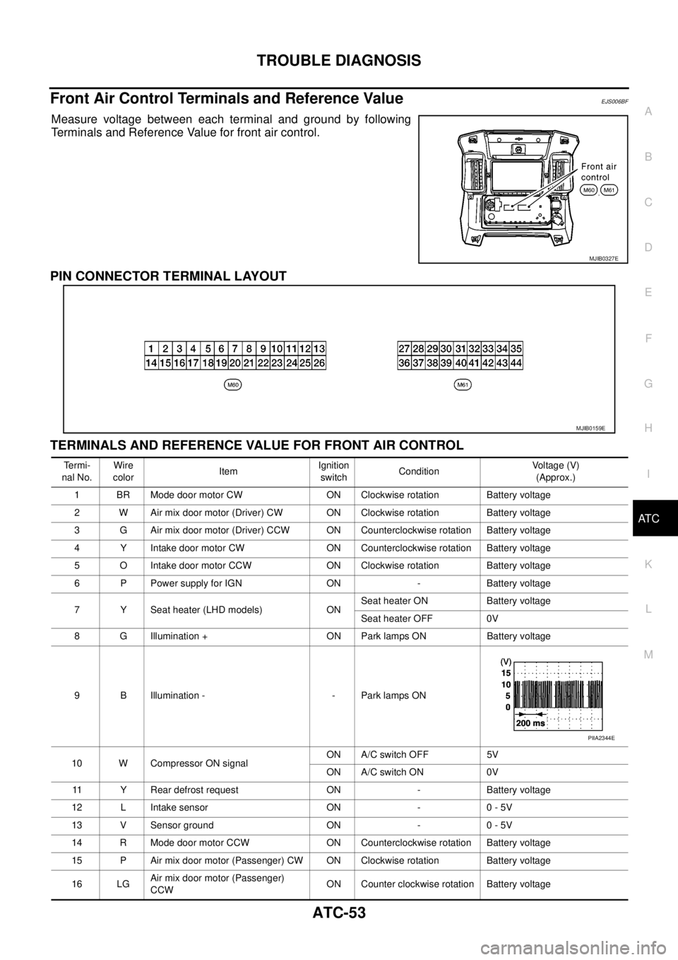
Measure voltage between each terminal and ground by following
Terminals and Reference Value for front air control.
PIN CONNECTOR TERMINAL LAYOUT
TERMINALS AND REFERENCE VALUE FOR FRONT AIR CONTROL
MJIB0327E
MJIB0159E
Te r m i -
nal No.Wire
colorItemIgnition
switchConditionVo l ta g e (V )
(Approx.)
1 BR Mode door motor CW ON Clockwise rotation Battery voltage
2 W Air mix door motor (Driver) CW ON Clockwise rotation Battery voltage
3 G Air mix door motor (Driver) CCW ON Counterclockwise rotation Battery voltage
4 Y Intake door motor CW ON Counterclockwise rotation Battery voltage
5 O Intake door motor CCW ON Clockwise rotation Battery voltage
6 P Power supply for IGN ON - Battery voltage
7 Y Seat heater (LHD models) ONSeat heater ON Battery voltage
Seat heater OFF 0V
8 G Illumination + ON Park lamps ON Battery voltage
9 B Illumination - - Park lamps ON
10 W Compressor ON signalON A/C switch OFF 5V
ON A/C switch ON 0V
11 Y Rear defrost request ON - Battery voltage
12 L Intake sensor ON - 0 - 5V
13 V Sensor ground ON - 0 - 5V
14 R Mode door motor CCW ON Counterclockwise rotation Battery voltage
15 P Air mix door motor (Passenger) CW ON Clockwise rotation Battery voltage
16 LGAir mix door motor (Passenger)
CCWON Counter clockwise rotation Battery voltage
PIIA2344E
Page 388 of 3171

ATC-54
TROUBLE DIAGNOSIS
19 GR Power supply for BAT - - Battery voltage
20 B Ground - - 0V
21 V Mode door motor feedback ON - 0 - 5V
22 SB Air mix door motor (Driver) feedback ON - 0 - 5V
23 G Sensor power ON - 5V
26 P Sensor return ON - 0V
27 R In-vehicle sensor signal ON - 0 - 5V
28 W Ambient sensor ON - 0 - 5V
29 G Optical sensor (Driver) ON - 0 - 5V
31 PPTC heater relay 1
(LHD models)ONRelay ON Battery voltage
Relay OFF 0V
32 V Variable blower control ON - 0 - 5V
33 BR In-vehicle sensor motor (+) ON - Battery voltage
34 O In-vehicle sensor motor (-) ON - 0V
35 LG Fan ON signalON Blower switch OFF 5V
ON Blower switch ON 0V
36 SBAir mix door motor (Passenger)
feedbackON - 0 - 5V
37 GR Optical sensor (Passenger) ON - 0 - 5V
38 B Blower request ONBlower motor OFF Battery voltage
Blower motor ON 0V
40 LGPTC heater relay 2
(LHD models)ONRelay ON Battery voltage
Relay OFF 0V
41 L CAN-H ON - 0 - 5V
42 P CAN-L ON - 0 - 5V
43 BRPTC heater relay 3
(LHD models)ONRelay ON Battery voltage
Relay OFF 0V
44 R Mirror heater (LHD models) ONHeater OFF 0V
Heater ON Battery voltage Te r m i -
nal No.Wire
colorItemIgnition
switchConditionVoltage (V)
(Approx.)
Page 396 of 3171
ATC-62
TROUBLE DIAGNOSIS
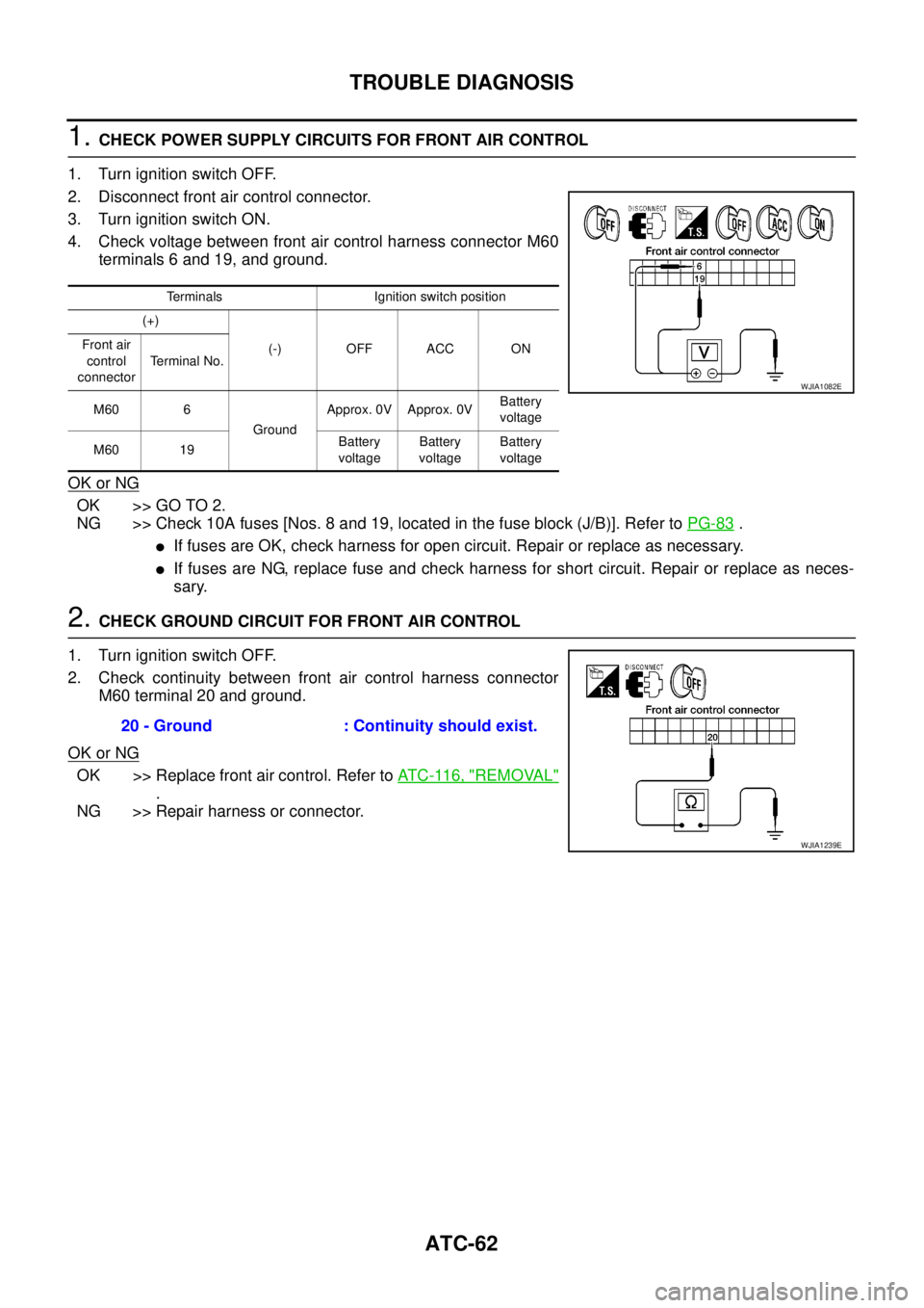
1.CHECK POWER SUPPLY CIRCUITS FOR FRONT AIR CONTROL
1. Turn ignition switch OFF.
2. Disconnect front air control connector.
3. Turn ignition switch ON.
4. Check voltage between front air control harness connector M60
terminals 6 and 19, and ground.
OK or NG
OK >> GO TO 2.
NG >> Check 10A fuses [Nos. 8 and 19, located in the fuse block (J/B)]. Refer toPG-83
.
lIf fuses are OK, check harness for open circuit. Repair or replace as necessary.
lIf fuses are NG, replace fuse and check harness for short circuit. Repair or replace as neces-
sary.
2.CHECK GROUND CIRCUIT FOR FRONT AIR CONTROL
1. Turn ignition switch OFF.
2. Check continuity between front air control harness connector
M60 terminal 20 and ground.
OK or NG
OK >> Replace front air control. Refer toAT C - 11 6 , "REMOVAL"
.
NG >> Repair harness or connector.
Terminals Ignition switch position
(+)
(-) OFF ACC ON Front air
control
connectorTerminal No.
M60 6
GroundApprox. 0V Approx. 0VBattery
voltage
M60 19Battery
voltageBattery
voltageBattery
voltage
WJIA1082E
20 - Ground : Continuity should exist.
WJIA1239E
Page 417 of 3171
![NISSAN NAVARA 2005 Repair Workshop Manual TROUBLE DIAGNOSIS
ATC-83
C
D
E
F
G
H
I
K
L
MA
B
AT C
1.CHECK FUSES
Check 15A fuses [No. 24 and 27, (located in the fuse and fusible link box)]. For fuse layout, refer toPG-84,
"FUSE AND FUSIBLE LINK B NISSAN NAVARA 2005 Repair Workshop Manual TROUBLE DIAGNOSIS
ATC-83
C
D
E
F
G
H
I
K
L
MA
B
AT C
1.CHECK FUSES
Check 15A fuses [No. 24 and 27, (located in the fuse and fusible link box)]. For fuse layout, refer toPG-84,
"FUSE AND FUSIBLE LINK B](/manual-img/5/57362/w960_57362-416.png)
TROUBLE DIAGNOSIS
ATC-83
C
D
E
F
G
H
I
K
L
MA
B
AT C
1.CHECK FUSES
Check 15A fuses [No. 24 and 27, (located in the fuse and fusible link box)]. For fuse layout, refer toPG-84,
"FUSE AND FUSIBLE LINK BOX".
OK or NG
OK >> GO TO 2.
NG >> GO TO 10.
2.CHECK BLOWER MOTOR POWER SUPPLY CIRCUIT
1. Turn ignition switch OFF.
2. Disconnect blower motor connector.
3. Turn ignition switch ON.
4. Turn the blower control dial to select any mode except off.
5. Check voltage between blower motor harness connector M94
terminal 2 and ground.
OK or NG
OK >> GO TO 12.
NG >> GO TO 3.
3.CHECK BLOWER MOTOR RELAY (SWITCH SIDE) POWER SUPPLY CIRCUIT
1. Turn ignition switch OFF.
2. Disconnect blower motor relay.
3. Check voltage between blower motor relay harness connector
E28 terminals 3 and 6 and ground.
OK or NG
OK >> GO TO 4.
NG >> Repair harness or connector.
4.CHECK BLOWER MOTOR RELAY
Refer toAT C - 8 6 , "
Blower Motor Relay".
OK or NG
OK >> GO TO 5.
NG >> Replace blower motor relay.
5.CHECK BLOWER MOTOR RELAY (SWITCH SIDE) CIRCUIT FOR OPEN
1. Turn ignition switch OFF.
2. Disconnect blower motor relay connector and blower motor con-
nector.
3. Check continuity between blower motor relay harness connector
E28 terminals 5 and 7 and blower motor harness connector M94
terminal 2.
OK or NG
OK >> GO TO 6.
NG >> Repair harness or connector.Fuses are good.
2 - Ground : Battery voltage.
MJIB0065E
3, 6 - Ground : Battery voltage.
MJIB0066E
5, 7 - 2 : Continuity should exist.
MJIB0067E
Page 418 of 3171
ATC-84
TROUBLE DIAGNOSIS
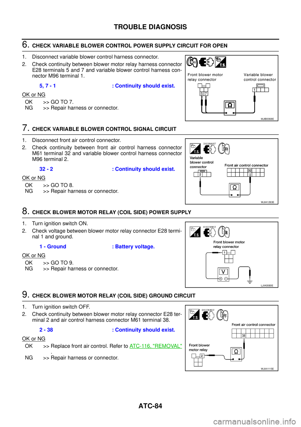
6.CHECK VARIABLE BLOWER CONTROL POWER SUPPLY CIRCUIT FOR OPEN
1. Disconnect variable blower control harness connector.
2. Check continuity between blower motor relay harness connector
E28 terminals 5 and 7 and variable blower control harness con-
nector M96 terminal 1.
OK or NG
OK >> GO TO 7.
NG >> Repair harness or connector.
7.CHECK VARIABLE BLOWER CONTROL SIGNAL CIRCUIT
1. Disconnect front air control connector.
2. Check continuity between front air control harness connector
M61 terminal 32 and variable blower control harness connector
M96 terminal 2.
OK or NG
OK >> GO TO 8.
NG >> Repair harness or connector.
8.CHECK BLOWER MOTOR RELAY (COIL SIDE) POWER SUPPLY
1. Turn ignition switch ON.
2. Check voltage between blower motor relay connector E28 termi-
nal 1 and ground.
OK or NG
OK >> GO TO 9.
NG >> Repair harness or connector.
9.CHECK BLOWER MOTOR RELAY (COIL SIDE) GROUND CIRCUIT
1. Turn ignition switch OFF.
2. Check continuity between blower motor relay connector E28 ter-
minal 2 and air control harness connector M61 terminal 38.
OK or NG
OK >> Replace front air control. Refer toAT C - 11 6 , "REMOVAL"
.
NG >> Repair harness or connector.5, 7 - 1 : Continuity should exist.
MJIB0068E
32 - 2 : Continuity should exist.
WJIA1263E
1 - Ground : Battery voltage.
LJIA0080E
2 - 38 : Continuity should exist.
WJIA1115E