2005 NISSAN NAVARA battery
[x] Cancel search: batteryPage 553 of 3171

TROUBLE DIAGNOSIS
AV-65
C
D
E
F
G
H
I
J
L
MA
B
AV
Example of Symptoms Not MalfunctionEKS00Q6T
BASIC OPERATION
NOTE:
Locations stored in the Address Book and other memory functions may be lost if the vehicle's battery is disconnected or becomes dis-
charged. If this occurs, service the vehicle's battery as necessary and re-enter the information in the Address Book.
VEHICLE ICON
Symptom Possible cause Possible solution
No image is displayed.The brightness is at the lowest setting. Adjust the brightness of the display.
The display is turned off.
Press and hold to turn on the display.
No voice guidance is available.
The volume is too high or too low.The volume is not set correctly, or it is turned off. Adjust the volume of voice guidance.
Volume guidance is not provided for narrow streets
(roads displayed in gray).This is not a malfunction.
No map is displayed on the screen.The map DVD-ROM is not inserted, or it is inserted
upside down.Insert the map DVD-ROM correctly.
A screen other than map screen is displayed. Press “MAP”.
Thescreenistoodim.
The movement is slow.The temperature in the interior of the vehicle is low.Wait until the interior of the vehicle has
warmed up.
Some pixels in the display are
darker or brighter than others.This condition is an inherent characteristic of liquid
crystal displays.This is not a malfunction.
Some menu items cannot be
selected.Some menu items become unavailable while the
vehicle is driven.Park the vehicle in a safe location, and
then operate the navigation system.
Symptom Possible cause Possible solution
Names of roads and locations dif-
fer between Plan view and Bird-
view™.This is because the quantity of the displayed infor-
mation is reduced so that the screen does not
become too crowded. There is also a chance that
names of the roads or locations may be displayed
multiple times, and the names appearing on the a
screen may be different because of a processing
procedure.This is not a malfunction.
The vehicle icon is not displayed in
the correct position.The vehicle was transported after the ignition switch
was turned off, for example, by a ferry or car trans-
porter.Drive the vehicle for a while on a road
whereGPScanbereceived.
The position and direction of the vehicle may be
incorrect depending on the driving environments and
the levels of positioning accuracy of the navigation
system.This is not a malfunction. Drive the vehi-
cle for a while to automatically correct the
position and direction of the vehicle icon.
Whenthevehicleistravellingona
new road, the vehicle icon is
located on another road nearby.Because the new road is not stored in the map data,
the system automatically places the vehicle ion on
the nearest road available.Updated road information will be included
in the next version of the map DVD-ROM.
The screen does not switch to the
night screen even after turning on
the headlights.The daytime screen was set the last time the head-
lights were turned on.Set the screen to the night screen mode
using when turning on the headlights.
The map does not scroll even
when the vehicle is moving.The current location map screen is not displayed. Press “MAP”.
The vehicle icon is not displayed. The current location map screen is not displayed. Press “MAP”.
The GPS indicator on the screen
remains gray.GPS signals cannot be received depending on the
vehicle location, such as in a parking garage, on a
road that has numerous tall buildings, etc.Drive on an open, straight road for a
while.
GPS signals cannot be received because objects
are placed on the rear parcel shelf.Remove the objects from the rear parcel
shelf.
A sufficient amount of GPS satellites are not avail-
able.Wait for the satellites to move locations
available for navigation system.
Page 575 of 3171

BCM (BODY CONTROL MODULE)
BCS-9
C
D
E
F
G
H
I
J
L
MA
B
BCS
MAJOR COMPONENTS AND CONTROL SYSTEM
CAN Communication System DescriptionEKS00PA2
Refer toLAN-23, "CAN COMMUNICATION".
System Input Output
Remote keyless entry system Keyfob
lAll-door locking actuator
lTurn signal lamp (LH, RH)
lCombination meter (Turn signal
lamp)
Power door lock system Door lock/unlock switch All-door locking actuator
Power supply (IGN) to power win-
dow and sunroofIgnition power supply Power window and sunroof system
Power supply (BAT) to power
window and sunroofBattery power supply Power window and sunroof system
Headlamp Combination switch IPDM E/R
Tail lamp Combination switch IPDM E/R
Front fog lamp Combination switch IPDM E/R
Rear fog lamp Combination switch
lRear fog lamp
lCombination meter
Turn signal lamp Combination switch
lTurn signal lamp
lCombination meter
Hazard lamp Hazard switch
lTurn signal lamp
lCombination meter
Room lamp timer
lKey switch
lKeyfob
lDoor lock/unlock switch
lFront door switch driver side
lAll-door switchInterior room lamp
Light warning chime
lCombination switch
lKey switch
lFront door switch driver sideCombination meter (warning buzzer)
Rain-sensing intermittent wiper
lCombination switch
lLight and rain sensorIPDM E/R
Vehicle-speed-sensing intermit-
tent wiper
lCombination switch
lCombination meterIPDM E/R
Headlamp washer Combination switch IPDM E/R
Rear window defogger
lRear window defogger switch
lIgnition switch (ACC, ON)IPDM E/R
A/C switch signal Front air control ECM
Blower fan switch signal Front air control ECM
Page 581 of 3171

BCM (BODY CONTROL MODULE)
BCS-15
C
D
E
F
G
H
I
J
L
MA
B
BCS
4. Select item to be diagnosed on “SELECT TEST ITEM” screen.
ITEMS OF EACH PART
NOTE:
CONSULT-II will only display systems the vehicle possesses.
WORK SUPPORT
Operation Procedure
1. Touch “BCM” on “SELECT TEST ITEM” screen.
PKIC0325E
System and itemCONSULT-II
displayDiagnostic test mode (Inspection by part)
WORK
SUPPORTSELF-
DIAG
RESULTSCAN DIAG
SUPPORT
MNTRDATA
MONITORECU
PA RT
NUMBERACTIVE
TESTCON-
FIGU-
RATION
BCM BCM´´ ´ ´ ´
Power door lock sys-
temDOOR LOCK´´´
Rear window defoggerREAR DEFOG-
GER´´
Warning chime BUZZER´´
Room lamp timer INT LAMP´´´
Headlamp HEAD LAMP´´´
Wiper WIPER´´´
Turn signal lamp
Hazard lampFLASHER´´
Blower fan switch sig-
nal
Air conditioner switch
signalAIR CONDI-
TONER´
Combination switch COMB SW´
NATS IMMU´´
Interior lamp battery
saverBATTERY
SAVER´´´
Theft alarm THEFT ALARM´´´
Retained power control RETAINED PWR´´´
Oil pressure switch SIGNAL BUFFER´´
PKIC0325E
Page 583 of 3171

BCM (BODY CONTROL MODULE)
BCS-17
C
D
E
F
G
H
I
J
L
MA
B
BCS
ConfigurationEKS00PA6
Refer toGI-37, "Configuration (BCM)".
Removal and Installation of BCMEKS00PA7
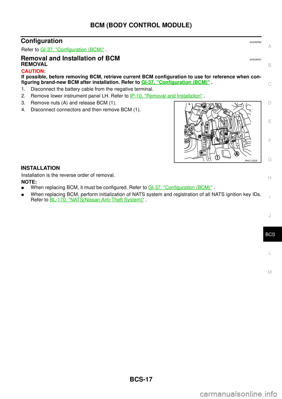
REMOVAL
CAUTION:
If possible, before removing BCM, retrieve current BCM configuration to use for reference when con-
figuring brand-new BCM after installation. Refer toGI-37, "
Configuration (BCM)".
1. Disconnect the battery cable from the negative terminal.
2. Remove lower instrument panel LH. Refer toIP-10, "
Removal and Installation".
3. Remove nuts (A) and release BCM (1).
4. Disconnect connectors and then remove BCM (1).
INSTALLATION
Installation is the reverse order of removal.
NOTE:
lWhen replacing BCM, it must be configured. Refer toGI-37, "Configuration (BCM)".
lWhen replacing BCM, perform initialization of NATS system and registration of all NATS ignition key IDs.
Refer toBL-170, "
NATS(Nissan Anti-Theft System)".
PKIC1222E
Page 586 of 3171

BL-2
Model) ..................................................................... 51
Check RH and LH Rear Door Lock Actuator Switch... 51
Check Door Lock/Unlock Switch ............................ 52
Check Door Lock/Unlock Switch Indicator .............. 53
POWER DOOR LOCK — SUPER LOCK — ............ 55
Component Parts and Harness Connector Location... 55
KING CAB ........................................................... 55
DOUBLE CAB ..................................................... 56
System Description ................................................. 57
OUTLINE ............................................................. 58
OPERATION ........................................................ 58
CAN Communication System Description .............. 59
CAN Communication Unit ....................................... 59
Schematic ............................................................... 60
Wiring Diagram —D/LOCK— ................................. 61
Terminals and Reference Value for BCM ................ 69
CONSULT-II Function (BCM) .................................. 70
CONSULT-II BASIC OPERATION PROCEDURE
... 70
CONSULT-II APPLICATION ITEMS .................... 71
Work Flow ............................................................... 72
Trouble Diagnoses Chart by Symptom ................... 72
Check Power Supply and Ground Circuit ............... 73
Check Door Switch ................................................. 74
CHECK DOOR SWITCH (DOUBLE CAB) .......... 74
CHECK DOOR SWITCH (KING CAB) ................ 76
Check Key Switch ................................................... 78
Check Front Door Lock Actuator (Driver Side) ....... 80
Check Front Door Lock Actuator (Passenger Side)... 81
Check Front Door Lock Actuator Switch ................. 81
Check Rear Door Lock Actuator LH (Double Cab
Models) ................................................................... 82
Check Rear Door Lock Actuator RH (Double Cab
Models) ................................................................... 82
Check RH and LH Rear Door Lock Actuator Switch
(Double Cab Models) .............................................. 83
Check Super Lock Actuator (Driver Side) ............... 83
Check Super Lock Actuator (Passenger Side) ....... 84
Check Super Lock Actuator (Rear LH) ................... 84
Check Super Lock Actuator (Rear RH) .................. 85
Check Door Lock/Unlock Switch ............................ 86
Check Door Lock/Unlock Switch Indicator .............. 87
MULTI-REMOTE CONTROL SYSTEM ..................... 89
Component Parts and Harness Connector Location... 89
KING CAB ........................................................... 89
DOUBLE CAB ..................................................... 90
System Description ................................................. 91
INPUTS ............................................................... 91
OPERATING PROCEDURE ................................ 91
CAN Communication System Description .............. 92
Wiring Diagram — MULTI — For LHD Models ....... 93
Wiring Diagram — MULTI — For RHD Models ...... 97
Terminals and Reference Value for BCM ..............101
CONSULT-II Function (BCM) ................................102
CONSULT-II Inspection Procedure .......................102
“MULTI REMOTE ENT” .....................................102
CONSULT-II Application Items .............................103
“MULTI REMOTE ENT” .....................................103
Trouble Diagnosis Procedure ...............................104Trouble Diagnosis Chart by Symptom ..................105
Check Keyfob Battery and Function .....................106
Check ACC Switch ................................................107
Check Door Switch ...............................................108
CHECK DOOR SWITCH (DOUBLE CAB) .........108
CHECK DOOR SWITCH (KING CAB) ...............110
Check Key Switch .................................................113
Check Hazard Function ........................................114
Check Map Lamp and Ignition Keyhole Illumination
Function ................................................................114
ID Code Entry Procedure ......................................115
KEYFOB ID SET UP ..........................................115
CONSULT-II INSPECTION PROCEDURE ........115
Remote Controller Battery Replacement ..............116
DOOR ......................................................................117
Fitting Adjustment (King Cab) ...............................117
FRONT DOOR ...................................................118
REAR DOOR .....................................................118
STRIKER ADJUSTMENT ..................................118
Fitting Adjustment (Double Cab) ...........................119
FRONT DOOR ...................................................120
REAR DOOR .....................................................120
STRIKER ADJUSTMENT ..................................120
Removal and Installation of Front Door ................120
REMOVAL ..........................................................120
INSTALLATION ..................................................121
Removal and Installation of Rear Door (King Cab).121
REMOVAL ..........................................................121
INSTALLATION ..................................................122
Removal and Installation of Rear Door (Double Cab)
.123
REMOVAL ..........................................................123
INSTALLATION ..................................................123
Removal and Installation of Door Weather-strip
(King Cab) .............................................................124
REMOVAL ..........................................................124
INSTALLATION ..................................................124
Removal and Installation of Door Weather-strip
(Double Cab) .........................................................125
REMOVAL ..........................................................125
INSTALLATION ..................................................125
FRONT DOOR LOCK ..............................................126
Removal and Installation .......................................126
REMOVAL ..........................................................126
INSTALLATION ..................................................129
REAR DOOR LOCK ................................................130
Removal and Installation of Rear Door Lock (King
Cab) ......................................................................130
REMOVAL ..........................................................130
INSTALLATION ..................................................131
Removal and Installation of Rear Door Lock (Double
Cab) ......................................................................132
REMOVAL ..........................................................132
INSTALLATION ..................................................134
TAIL GATE ...............................................................135
Component Parts Location ...................................135
FUEL FILLER LID OPENER ...................................136
Removal and Installation of Fuel Filler Lid ............136
REMOVAL ..........................................................136
Page 618 of 3171
![NISSAN NAVARA 2005 Repair Workshop Manual BL-34
POWER DOOR LOCK SYSTEM
Terminals and Reference Value for BCM
EIS00D7Z
*: Double cab modelTERMI-
NALWIRE
COLORITEM CONDITIONVOLTAGE [V]
(Approx.)
3 Y Ignition switch Ignition switch ON Battery vo NISSAN NAVARA 2005 Repair Workshop Manual BL-34
POWER DOOR LOCK SYSTEM
Terminals and Reference Value for BCM
EIS00D7Z
*: Double cab modelTERMI-
NALWIRE
COLORITEM CONDITIONVOLTAGE [V]
(Approx.)
3 Y Ignition switch Ignition switch ON Battery vo](/manual-img/5/57362/w960_57362-617.png)
BL-34
POWER DOOR LOCK SYSTEM
Terminals and Reference Value for BCM
EIS00D7Z
*: Double cab modelTERMI-
NALWIRE
COLORITEM CONDITIONVOLTAGE [V]
(Approx.)
3 Y Ignition switch Ignition switch ON Battery voltage
5RKeyswitchKey switch ON Battery voltage
Key switch OFF 0
12 L Rear door switch RH* ON (Door is opened)®OFF (Door is closed) 0®Battery voltage
14 LGFront door switch
(Passenger side)ON (Door is opened)®OFF (Door is closed) 0®Battery voltage
15 SBFront door switch
(Driver side)ON (Door is opened)®OFF (Door is closed) 0®Battery voltage
16 P Rear door switch LH* ON (Door is opened)®OFF (Door is closed) 0®Battery voltage
17 WDoor lock/unlock switch indi-
catorAll door closedLock operation
(Illuminates)Battery voltage
Other than above 0
21 P CAN-L — —
22 L CAN-H — —
32 GR Door lock/unlock switch All door closedUnlock 0
Other than above 5
34 O Door lock/unlock switch All door closedLock 0
Other than above 5
41 YPower switch
(Fuse)— Battery voltage
54 GPassenger and rear door lock
actuators*1 (unlock)Door lock/unlock switch (Free®Lock) 0®Battery voltage®0
55 B Ground — 0
56 V All door lock actuators (lock) Door lock/unlock switch (Free®Lock) 0®Battery voltage®0
57 WPower source
(Fusible link)— Battery voltage
60 GDriver door lock actuator
(unlock)Door lock/unlock switch (Free®Lock) 0®Battery voltage®0
Page 622 of 3171

BL-38
POWER DOOR LOCK SYSTEM
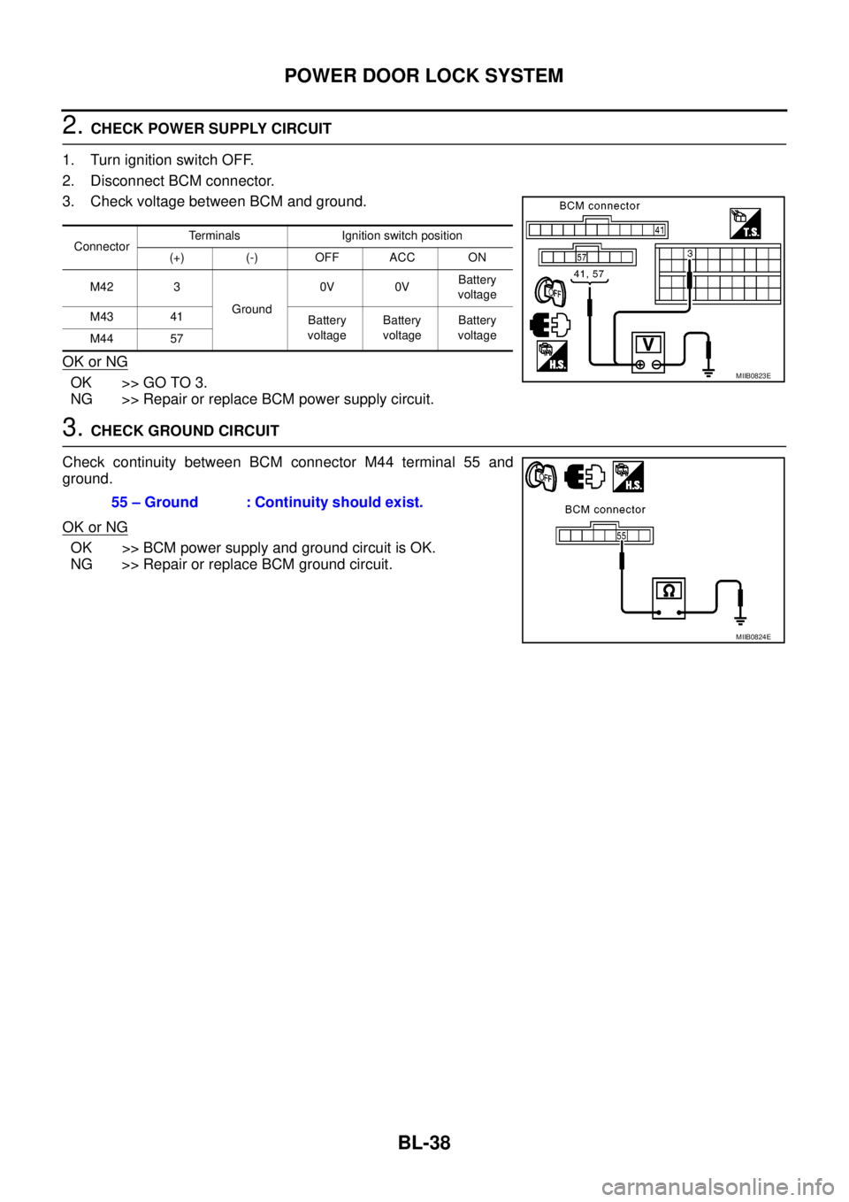
2.CHECK POWER SUPPLY CIRCUIT
1. Turn ignition switch OFF.
2. Disconnect BCM connector.
3. Check voltage between BCM and ground.
OK or NG
OK >> GO TO 3.
NG >> Repair or replace BCM power supply circuit.
3.CHECK GROUND CIRCUIT
Check continuity between BCM connector M44 terminal 55 and
ground.
OK or NG
OK >> BCM power supply and ground circuit is OK.
NG >> Repair or replace BCM ground circuit.
ConnectorTerminals Ignition switch position
(+) (-) OFF ACC ON
M42 3
Ground0V 0VBattery
voltage
M43 41
Battery
voltageBattery
voltageBattery
voltage
M44 57
MIIB0823E
55 – Ground : Continuity should exist.
MIIB0824E
Page 623 of 3171

POWERDOORLOCKSYSTEM
BL-39
C
D
E
F
G
H
J
K
L
MA
B
BL
Check Door SwitchEIS00D85
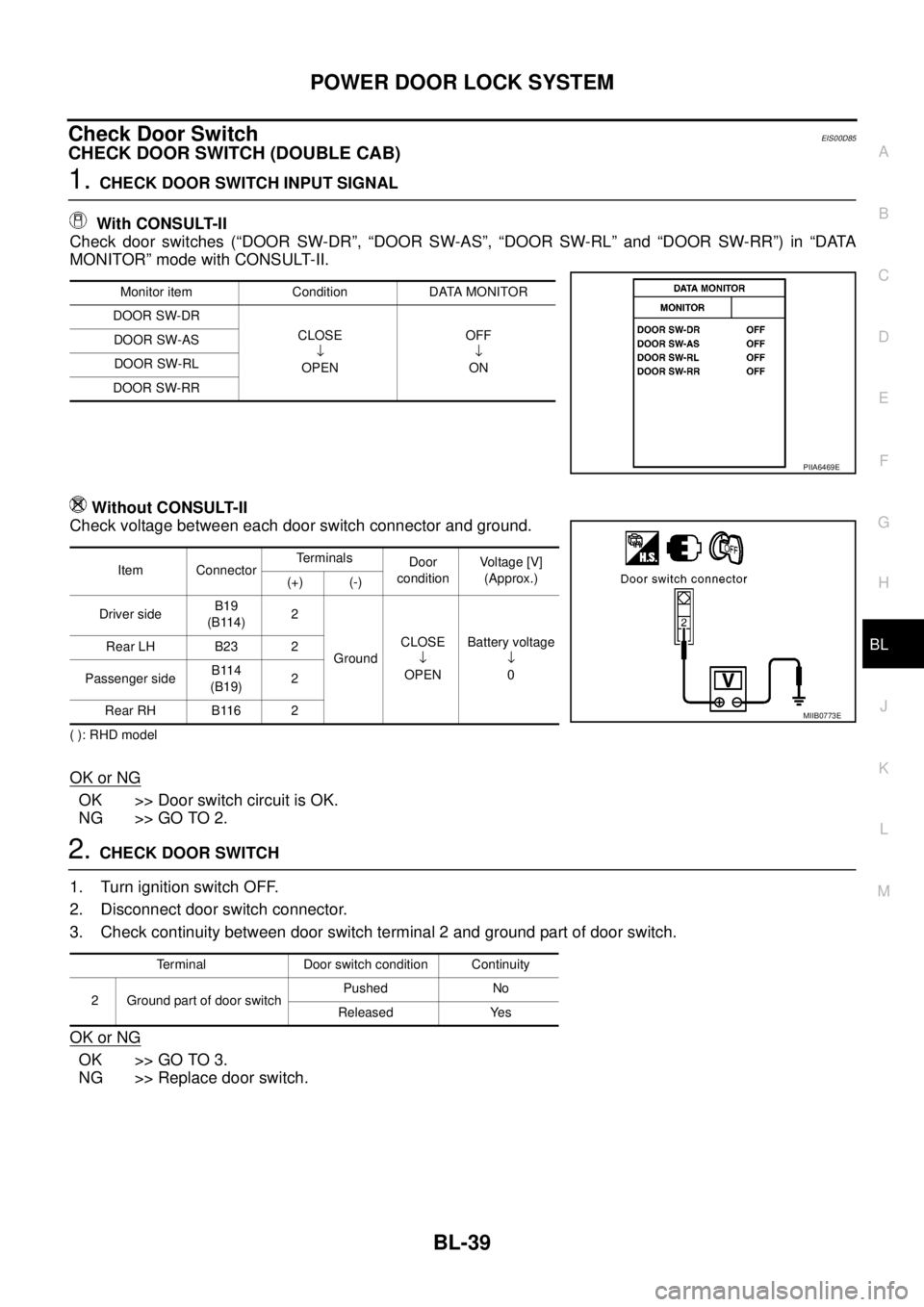
CHECK DOOR SWITCH (DOUBLE CAB)
1.CHECK DOOR SWITCH INPUT SIGNAL
With CONSULT-II
Check door switches (“DOOR SW-DR”, “DOOR SW-AS”, “DOOR SW-RL” and “DOOR SW-RR”) in “DATA
MONITOR” mode with CONSULT-II.
Without CONSULT-II
Check voltage between each door switch connector and ground.
( ): RHD model
OK or NG
OK >> Door switch circuit is OK.
NG >> GO TO 2.
2.CHECK DOOR SWITCH
1. Turn ignition switch OFF.
2. Disconnect door switch connector.
3. Check continuity between door switch terminal 2 and ground part of door switch.
OK or NG
OK >> GO TO 3.
NG >> Replace door switch.
Monitor item Condition DATA MONITOR
DOOR SW-DR
CLOSE
¯
OPENOFF
¯
ON DOOR SW-AS
DOOR SW-RL
DOOR SW-RR
PIIA6469E
Item ConnectorTerminals
Door
conditionVo l ta g e [V ]
(Approx.)
(+) (-)
Driver sideB19
(B114)2
GroundCLOSE
¯
OPENBattery voltage
¯
0 Rear LH B23 2
Passenger sideB114
(B19)2
Rear RH B116 2
MIIB0773E
Terminal Door switch condition Continuity
2 Ground part of door switchPushed No
Released Yes