Page 707 of 3171

DOOR
BL-123
C
D
E
F
G
H
J
K
L
MA
B
BL
Removal and Installation of Rear Door (Double Cab)EIS00DUN
CAUTION:
lWhen removing and installing the rear door assembly, support the door with a jack and cloth to
protect the door and body.
lWhen removing and installing rear door assembly, be sure to carry out the fitting adjustment
REfer toBL-119, "
Fitting Adjustment (Double Cab)".
lCheck the hinge rotating part for poor lubrication. If necessary, apply “body grease”.
lAfter installing, apply touch-up paint (the body color) onto the head of the hinge mounting nuts.
lOperate with two workers, because of its heavy weight.
lAfter installing, check operation.
REMOVAL
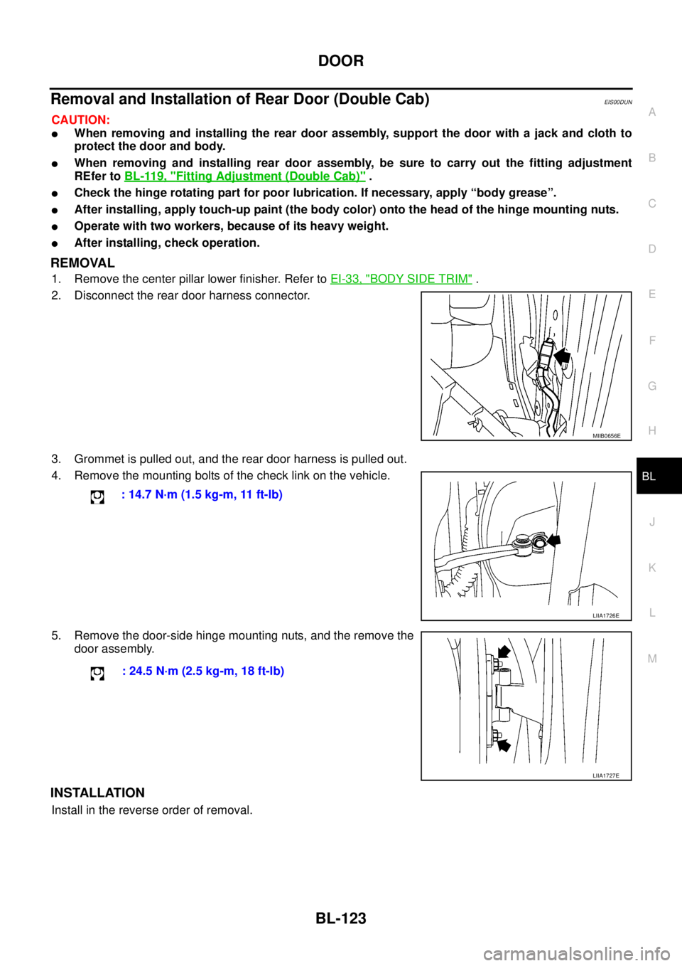
1. Remove the center pillar lower finisher. Refer toEI-33, "BODY SIDE TRIM".
2. Disconnect the rear door harness connector.
3. Grommet is pulled out, and the rear door harness is pulled out.
4. Remove the mounting bolts of the check link on the vehicle.
5. Remove the door-side hinge mounting nuts, and the remove the
door assembly.
INSTALLATION
Install in the reverse order of removal.
MIIB0656E
: 14.7 N·m (1.5 kg-m, 11 ft-lb)
LIIA1726E
: 24.5 N·m (2.5 kg-m, 18 ft-lb)
LIIA1727E
Page 708 of 3171
BL-124
DOOR
Removal and Installation of Door Weather-strip (King Cab)
EIS00BQ6
REMOVAL
CAUTION:
After removal, do not pull strongly on the weather-strip.
Remove the weather-strip clips, and remove weather strip.
INSTALLATION
Install in the reverse order of removal.
1. Front door outer 2. Front door weather-strip 3. Rear door outer
4. Rear door weather-strip 5. Sill outer 6. Body side outer
MIIB0921E
Page 709 of 3171
DOOR
BL-125
C
D
E
F
G
H
J
K
L
MA
B
BL
Removal and Installation of Door Weather-strip (Double Cab)EIS00DWU
REMOVAL
CAUTION:
After removal, do not pull strongly on the weather-strip.
Remove the weather-strip clips, and remove weather-strip.
INSTALLATION
Install in the reverse order of removal.
1. Front door outer 2. Front door weather-strip 3. Rear door outer
4. Rear door weather-strip 5. Sill outer 6. Body side outer
MIIB0646E
Page 720 of 3171
BL-136
FUEL FILLER LID OPENER
FUEL FILLER LID OPENER
PFP:78820
Removal and Installation of Fuel Filler LidEIS00BLA
REMOVAL
1. Fully open fuel filler lid.
2. Remove the fuel filler lid mounting screws, and then remove the
fuel filler lid.
INSTALLATION
Install in the reverse order of removal.
CAUTION:
After installing, apply touch-up paint (the body color) onto the head of the mounting screws.
1. Fuel filler lid 2. Fuel filler lid bumper 3. Cylinder lock clip
4. Fuel filler lid key cylinder 5. Fuel filler lid lock striker 6. Fuel cap assembly
MIIB0980E
MIIB0650E
Page 725 of 3171

THEFT WARNING SYSTEM
BL-141
C
D
E
F
G
H
J
K
L
MA
B
BL
2. A door is unlocked without using the keyfob.
3. Disconnect and connecting the battery connector before canceling armed phase.
POWER SUPPLY AND GROUND CIRCUIT
Power is supplied at all times
lthrough 10A fuse [No.19, located in the fuse block (J/B)]
lto combination meter (security indicator lamp) terminal 3
lthrough 50A fusible link (letterG, located in the fuse and fusible link box)
lto BCM terminal 57
lthrough 10A fuse [No. 21, located in the fuse block (J/B)]
lto BCM terminal 41
lthrough 15A fuse (No. 30, located in the fuse and fusible link box)
lto horn relay terminal 2
lthrough 20A fuse (No. 52, located in the IPDM E/R)
lthrough 20A fuse (No. 53, located in the IPDM E/R),
lto IPDM E/R internal CPU.
With the ignition switch in the ACC or ON position, power is supplied
lthrough 10A fuse [No. 4, located in the fuse block (J/B)]
lto BCM terminal 4.
Ground is supplied
lto BCM terminal 55
lthrough body grounds M21, M80 and M83
lto IPDM E/R terminals 38 and 59
lthrough body ground E21, E41 and E61.
INITIAL CONDITION TO ACTIVATE THE SYSTEM
The operation of the theft warning system is controlled by the engine hood and doors.
To activate the theft warning system, BCM must receive signals indicating the doors are closed and locked.
When a door is open, BCM terminal 12, 14, 15 or 16 receives a ground signal from each door switch.
When the engine hood is open, IPDM E/R terminal 41 receives a ground signal
THEFT WARNING SYSTEM ALARM OPERATION
The vehicle security system is triggered by
lopening a door
lopening the hood
ldetecting battery disconnect/connection.
The vehicle security system will be triggered once the system is in armed phase,
when BCM receives a ground signal at terminals 12, 14, 15, 16 (door switch) or IPDM E/R receives a ground
signal at terminal 41 (hood switch).
When the vehicle security system is triggered, siren control unit or horn is activate.
The alarm automatically turns off after 30 seconds, but will reactivate if the vehicle is tampered with again.
THEFT WARNING SYSTEM DEACTIVATION
To deactivate the theft warning system, a door must be unlocked with keyfob.
When the BCM receives either one of these signals or unlock signal from keyfob the theft warning system is
deactivated. (Disarmed phase)
CAN Communication System DescriptionEIS00DBY
Refer toLAN-23, "CAN COMMUNICATION".
Page 773 of 3171
CAB AND REAR BODY
BL-189
C
D
E
F
G
H
J
K
L
MA
B
BL
CAB AND REAR BODYPFP:93020
Body Mounting (King Cab)EIS00DI6
lWhen removing, be sure to replace bolts and nuts (sealant applied bolts or self-lock nuts are used for all
mounting).
lUnless otherwise noted, the bushings and insulators have paint marks that are to be installed facing out-
ward.
1. Cab mounting insulator (1st) 2. Cab mounting insulator (2nd) 3. Cab mounting insulator (3rd)
MIIB0935E
Page 774 of 3171
BL-190
CAB AND REAR BODY
Body Mounting (Double Cab)
EIS00DWV
lWhen removing, be sure to replace bolts and nuts (sealant applied bolts or self-lock nuts are used for all
mounting).
lUnless otherwise noted, the bushings and insulators have paint marks that are to be installed facing out-
ward.
1. Cab mounting insulator (1st) 2. Cab mounting insulator (2nd) 3. Cab mounting insulator (3rd)
4. Cab mounting insulator (4th)
MIIB0936E
Page 775 of 3171
BODY REPAIR
BL-191
C
D
E
F
G
H
J
K
L
MA
B
BL
BODY REPAIRPFP:60100
Body AlignmentEIS00DGG
DESCRIPTION
lAll dimensions indicated in the figures are actual.
lWhen using a tracking gauge, adjust both pointers to equal length. Then check the pointers and gauge
itself to make sure there is no free play.
lWhen a measuring tape is used, check to be sure there is no elongation, twisting or bending.
lMeasurements should be taken at the center of the mounting holes.
lAn asterisk (*) following the value at the measuring point indicates that the measuring point on the other
side is symmetrically the same value.
lThe coordinates of the measurement points are the distances measured from the standard line of²X²,²Y²
and²Z².
LIIA1506E