2005 NISSAN NAVARA body
[x] Cancel search: bodyPage 2827 of 3171
SB-10
SEAT BELTS
REMOVAL OF SEAT BELT RETRACTOR - OUTBOARD
1. Remove seat belt lower anchor cover and bolt.
2. Remove the D-ring anchor bolt cover and D-ring anchor bolt.
3. Remove the upper and lower rear pillar finishers. Refer toEI-33, "
BODY SIDE TRIM".
4. Remove seat belt retractor and belt bolt and assembly from vehicle.
INSTALLATION OF SEAT BELT RETRACTOR - OUTBOARD
Installation is in the reverse order of removal.
REMOVAL OF SEAT BELT RETRACTOR - CENTER
1. Position the rear seat cushion in the folded up position.
2. Remove seat belt lower anchor cover and bolt.
3. Remove rear panel upper finisher. Refer toEI-33, "
BODY SIDE TRIM".
4. Remove center belt shoulder guide bolts.
5. Remove seat belt retractor and belt bolt and assembly from vehicle.
INSTALLATION OF SEAT BELT RETRACTOR - CENTER
Installation is in the reverse order of removal.
REMOVAL OF SEAT BELT BUCKLE
1. Position rear seat cushion in the folded up position.
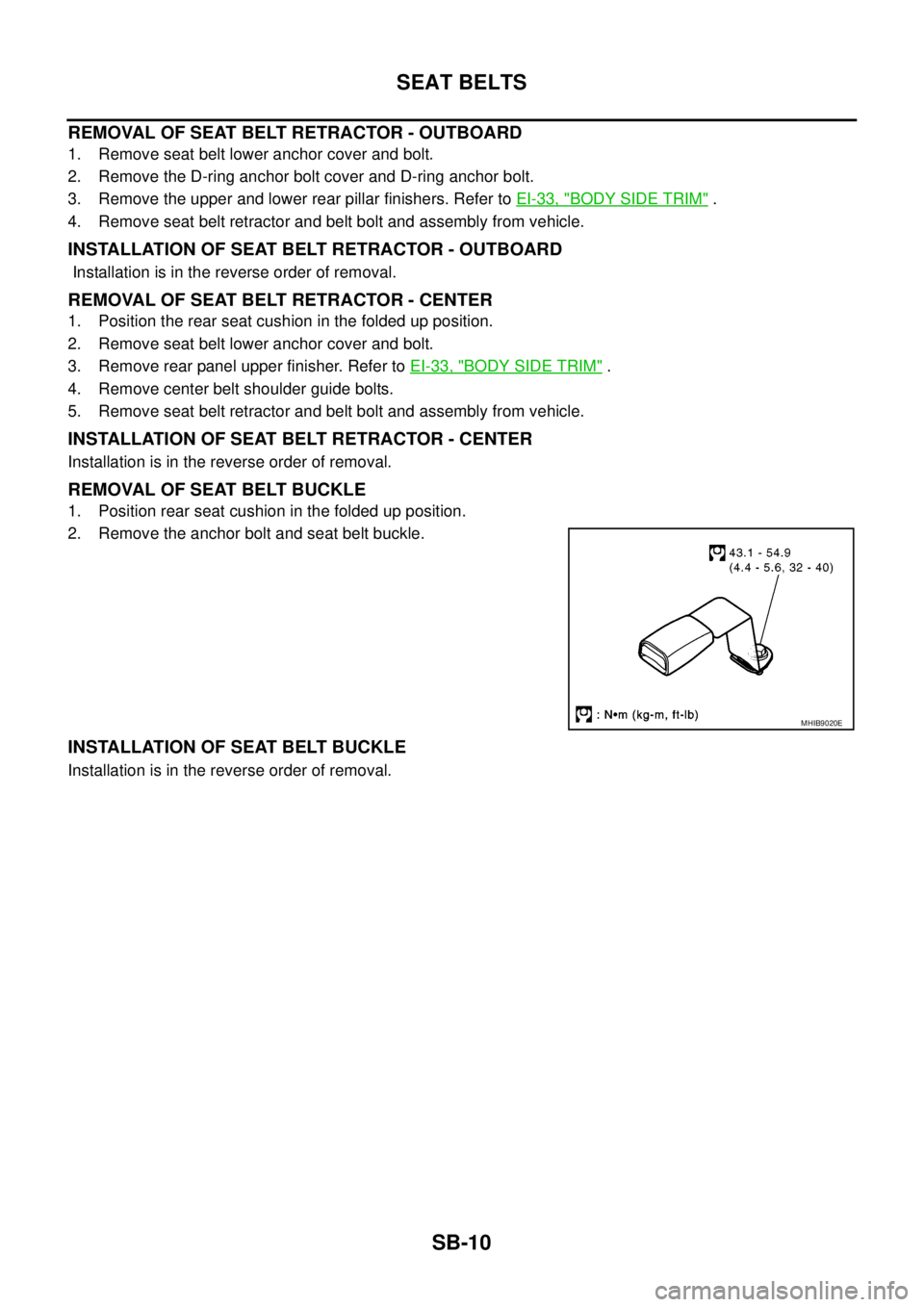
2. Remove the anchor bolt and seat belt buckle.
INSTALLATION OF SEAT BELT BUCKLE
Installation is in the reverse order of removal.
MHIB9020E
Page 2860 of 3171
STARTING SYSTEM
SC-27
C
D
E
F
G
H
I
J
L
MA
B
SC
STARTING SYSTEMPFP:00011
System DescriptionEKS00MZJ
A/T MODELS
Power is supplied at all times:
lto starter motor terminal 1 and
lthrough 40A fusible link (letterJ, located in the fuse and fusible link box)
lto ignition switch terminal 1.
with the ignition switch in the START position, power is supplied:
lfrom ignition switch terminal 5
lto IPDM E/R terminal 21.
With the ignition switch in the ON or START position, power is supplied to IPDM E/R CPU, and
the selector lever in the P or N position, power is supplied:
lthrough A/T assembly terminal 9
lto IPDM E/R terminal 48.
Ground is supplied at all times:
lto IPDM E/R terminals 38 and 59
lfrom body grounds E21, E41 and E61.
Then the starter relay is turned ON.
The IPDM E/R starter relay is energized and power is supplied:
lfrom terminal 19 of IPDM E/R
lto terminal 2 of the starter motor.
The starter motor plunger closes and provides a closed circuit between the battery and the starter motor. The
starter motor is grounded to the cylinder block. With power and ground supplied, the starter motor operates.
M/T MODELS
Power is supplied at all times:
lto starter motor terminal 1 and
lthrough 40A fusible link (letterJ, located in the fuse and fusible link box)
lto ignition switch terminal 1.
with the ignition switch in the START position, power is supplied:
lfrom ignition switch terminal 5
lto IPDM E/R terminal 21.
With the start signal is input to IPDM E/R CPU, power is supplied:
lthrough IPDM E/R terminal 14
lto IPDM E/R terminal 48.
Ground is supplied at all times:
lto IPDM E/R terminals 38 and 59
lfrom body grounds E21, E41 and E61.
Then the starter relay is turned ON.
The IPDM E/R starter relay is energized and power is supplied:
lfrom terminal 19 of IPDM E/R
lto terminal 2 of the starter motor.
The starter motor plunger closes and provides a closed circuit between the battery and the starter motor. The
starter motor is grounded to the cylinder block. With power and ground supplied, the starter motor operates.
Page 2866 of 3171
STARTING SYSTEM
SC-33
C
D
E
F
G
H
I
J
L
MA
B
SC
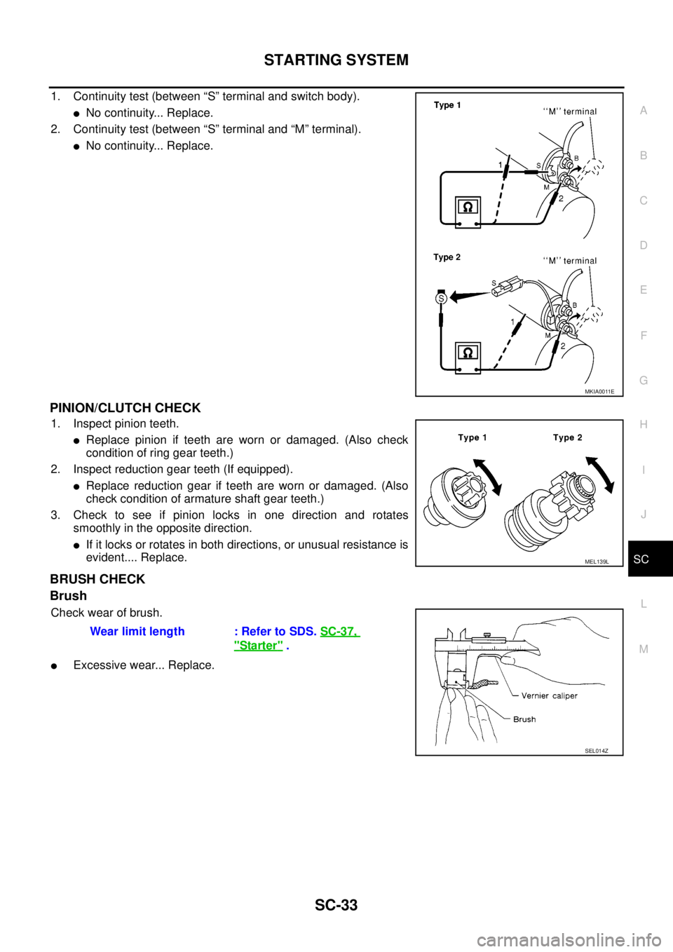
1. Continuity test (between “S” terminal and switch body).
lNo continuity... Replace.
2. Continuity test (between “S” terminal and “M” terminal).
lNo continuity... Replace.
PINION/CLUTCH CHECK
1. Inspect pinion teeth.
lReplace pinion if teeth are worn or damaged. (Also check
condition of ring gear teeth.)
2. Inspect reduction gear teeth (If equipped).
lReplace reduction gear if teeth are worn or damaged. (Also
check condition of armature shaft gear teeth.)
3. Check to see if pinion locks in one direction and rotates
smoothly in the opposite direction.
lIf it locks or rotates in both directions, or unusual resistance is
evident.... Replace.
BRUSH CHECK
Brush
Check wear of brush.
lExcessive wear... Replace.
MKIA0011E
MEL139L
Wear limit length : Refer to SDS.SC-37,
"Starter".
SEL014Z
Page 2872 of 3171
SE-1
SEAT
IBODY
CONTENTS
C
D
E
F
G
H
J
K
L
M
SECTIONSE
A
B
SE
SEAT
PRECAUTIONS .......................................................... 2
Precautions for Supplemental Restraint System
(SRS)“AIRBAG”and“SEATBELTPRE-TEN-
SIONER” .................................................................. 2
Precautions for Work ................................................ 2
PREPARATION ........................................................... 3
Commercial Service Tool ......................................... 3
SQUEAK AND RATTLE TROUBLE DIAGNOSES..... 4
Work Flow ................................................................ 4
CUSTOMER INTERVIEW ..................................... 4
DUPLICATE THE NOISE AND TEST DRIVE ....... 5
CHECK RELATED SERVICE BULLETINS ........... 5
LOCATE THE NOISE AND IDENTIFY THE
ROOT CAUSE ...................................................... 5
REPAIR THE CAUSE ........................................... 5
CONFIRM THE REPAIR ....................................... 6
Generic Squeak and Rattle Troubleshooting ........... 6
INSTRUMENT PANEL .......................................... 6
CENTER CONSOLE ............................................. 6
DOORS ................................................................. 6
TRUNK .................................................................. 7
SUNROOF/HEADLINING ..................................... 7
SEATS ................................................................... 7
UNDERHOOD ....................................................... 7
Diagnostic Worksheet .............................................. 8
POWER SEAT .......................................................... 10Wiring Diagram – SEAT – / For LHD Models ......... 10
Wiring Diagram – SEAT – / For RHD Models ......... 11
HEATED SEAT .......................................................... 12
Description .............................................................. 12
Schematic ............................................................... 13
Wiring Diagram – HSEAT – / For LHD Models ....... 14
Wiring Diagram – HSEAT – / For RHD Models ...... 17
FRONT SEAT ............................................................ 20
Components Parts Drawing .................................... 20
DRIVER SEAT ..................................................... 20
PASSENGER SEAT ............................................ 22
Removal and Installation ........................................ 23
REMOVAL ........................................................... 23
INSTALLATION ................................................... 24
Disassembly and Assembly .................................... 24
SEAT CUSHION (POWER SEAT) ....................... 24
SEAT CUSHION (MANUAL SEAT) ..................... 25
SEATBACK (POWER AND MANUAL SEAT) ...... 26
SEATBACK (FRAT FOLD SEAT) ........................ 27
REAR SEAT .............................................................. 29
Removal and Installation ........................................ 29
JUMP SEAT (KING CAB) .................................... 29
BENCH SEAT LH (DOUBLE CAB) ...................... 30
BENCH SEAT RH (DOUBLE CAB) ..................... 30
Disassembly and Assembly .................................... 32
Page 2876 of 3171
SQUEAK AND RATTLE TROUBLE DIAGNOSES
SE-5
C
D
E
F
G
H
J
K
L
MA
B
SE
DUPLICATE THE NOISE AND TEST DRIVE
If possible, drive the vehicle with the customer until the noise is duplicated. Note any additional information on
the Diagnostic Worksheet regarding the conditions or location of the noise. This information can be used to
duplicate the same conditions when you confirm the repair.
If the noise can be duplicated easily during the test drive, to help identify the source of the noise, try to dupli-
cate the noise with the vehicle stopped by doing one or all of the following:
1) Close a door.
2) Tap or push/pull around the area where the noise appears to be coming from.
3) Rev the engine.
4) Use a floor jack to recreate vehicle “twist”.
5) At idle, apply engine load (electrical load, half-clutch on M/T models, drive position on A/T models).
6) Raisethevehicleonahoistandhitatirewitharubberhammer.
lDrive the vehicle and attempt to duplicate the conditions the customer states exist when the noise occurs.
lIf it is difficult to duplicate the noise, drive the vehicle slowly on an undulating or rough road to stress the
vehicle body.
CHECK RELATED SERVICE BULLETINS
After verifying the customer concern or symptom, check ASIST for Technical Service Bulletins (TSBs) related
to that concern or symptom.
If a TSB relates to the symptom, follow the procedure to repair the noise.
LOCATE THE NOISE AND IDENTIFY THE ROOT CAUSE
1. Narrow down the noise to a general area. To help pinpoint the source of the noise, use a listening tool
(Engine Ear or mechanics stethoscope).
2. Narrow down the noise to a more specific area and identify the cause of the noise by:
lremoving the components in the area that you suspect the noise is coming from.
Do not use too much force when removing clips and fasteners, otherwise clips and fastener can be broken
or lost during the repair, resulting in the creation of new noise.
ltapping or pushing/pulling the component that you suspect is causing the noise.
Do not tap or push/pull the component with excessive force, otherwise the noise will be eliminated only
temporarily.
lfeeling for a vibration with your hand by touching the component(s) that you suspect is (are) causing the
noise.
lplacing a piece of paper between components that you suspect are causing the noise.
llooking for loose components and contact marks.
Refer toSE-6, "
Generic Squeak and Rattle Troubleshooting".
REPAIR THE CAUSE
lIf the cause is a loose component, tighten the component securely.
lIf the cause is insufficient clearance between components:
–separate components by repositioning or loosening and retightening the component, if possible.
–insulate components with a suitable insulator such as urethane pads, foam blocks, felt cloth tape or ure-
thane tape are available through your authorized Nissan Parts Department.
CAUTION:
Do not use excessive force as many components are constructed of plastic and may be damaged.
NOTE:
Always check with the Parts Department for the latest parts information.
Each item can be ordered separately as needed.
URETHANE PADS [1.5 mm (0.059 in) thick]
Insulates connectors, harness, etc.
76268-9E005: 100´135 mm (3.94´5.31 in)/76884-71L01: 60´85 mm (2.36´3.35 in)/76884-71L02: 15´
25 mm (0.59´0.98 in)
INSULATOR (Foam blocks)
Insulates components from contact. Can be used to fill space behind a panel.
73982-9E000: 45 mm (1.77 in) thick, 50´50 mm (1.97´1.97 in)/73982-50Y00: 10 mm (0.39 in) thick, 50
´50 mm (1.97´1.97 in)
INSULATOR (Light foam block)
80845-71L00: 30 mm (1.18 in) thick, 30´50 mm (1.18´1.97 in)
Page 3115 of 3171
WW-4
FRONT WIPER AND WASHER SYSTEM
FRONT WIPER AND WASHER SYSTEM
PFP:28810
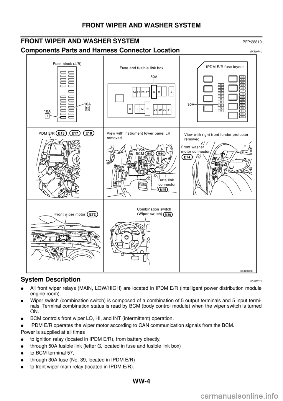
Components Parts and Harness Connector LocationEKS00P4U
System DescriptionEKS00P4V
lAll front wiper relays (MAIN, LOW/HIGH) are located in IPDM E/R (intelligent power distribution module
engine room).
lWiper switch (combination switch) is composed of a combination of 5 output terminals and 5 input termi-
nals. Terminal combination status is read by BCM (body control module) when the wiper switch is turned
ON.
lBCM controls front wiper LO, HI, and INT (intermittent) operation.
lIPDM E/R operates the wiper motor according to CAN communication signals from the BCM.
Power is supplied at all times
lto ignition relay (located in IPDM E/R), from battery directly,
lthrough 50A fusible link (letter G, located in fuse and fusible link box)
lto BCM terminal 57,
lthrough 30A fuse (No. 39, located in IPDM E/R)
lto front wiper main relay (located in IPDM E/R).
SKIB6805E
Page 3150 of 3171
HEADLAMP WASHER
WW-39
C
D
E
F
G
H
I
J
L
MA
B
WW
HEADLAMP WASHERPFP:28620
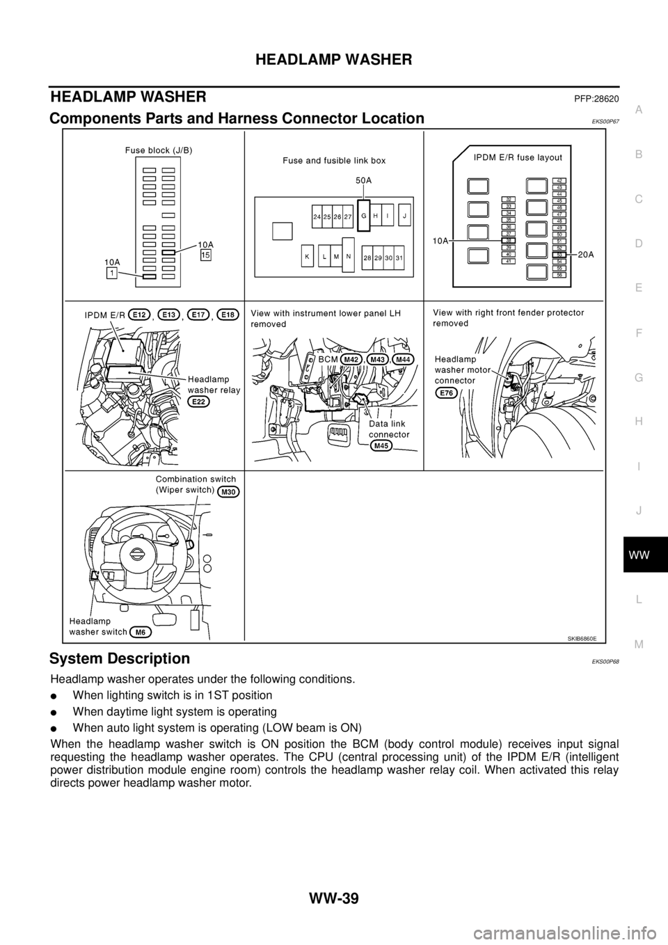
Components Parts and Harness Connector LocationEKS00P67
System DescriptionEKS00P68
Headlamp washer operates under the following conditions.
lWhen lighting switch is in 1ST position
lWhen daytime light system is operating
lWhen auto light system is operating (LOW beam is ON)
When the headlamp washer switch is ON position the BCM (body control module) receives input signal
requesting the headlamp washer operates. The CPU (central processing unit) of the IPDM E/R (intelligent
power distribution module engine room) controls the headlamp washer relay coil. When activated this relay
directs power headlamp washer motor.
SKIB6860E