Page 2564 of 3171
GROUND CIRCUIT
PG-35
C
D
E
F
G
H
I
J
L
MA
B
PG
BODY HARNESS (LH SIDE)
MKWA3827E
Page 2565 of 3171
PG-36
GROUND CIRCUIT
BODY HARNESS (RH SIDE)
MKWA3828E
Page 2567 of 3171
PG-38
HARNESS
HARNESS
PFP:24010
Harness LayoutEKS00LJ8
HOW TO READ HARNESS LAYOUT
The following Harness Layouts use a map style grid to help locate
connectors on the drawings:
lMain Harness
lEngine Room Harness
lEngine Control Harness
lChassis Harness
lBody Harness
lRoom Lamp Harness
lDoor Harness
To use the grid reference
1. Find the desired connector number on the connector list.
2. Find the grid reference.
3. On the drawing, find the crossing of the grid reference letter column and number row.
4. Find the connector number in the crossing zone.
5. Follow the line (if used) to the connector.
CONNECTOR SYMBOL
Main symbols of connector (in Harness Layout) are indicated below.
SEL252V
Connector typeWater proof type Standard type
Male Female Male Female
lCavity: Less than 4
lRelay connector
lCavity: From 5 to 8
lCavity: More than 9
lGround terminal etc.
—
Page 2583 of 3171
PG-54
HARNESS
BODY HARNESS (LH SIDE)/DOUBLE CAB MODELS
MKWA3859E
Page 2585 of 3171
PG-56
HARNESS
BODY HARNESS (RH SIDE)/DOUBLE CAB MODELS
MKWA3861E
Page 2587 of 3171
PG-58
HARNESS
BODY HARNESS (LH SIDE)/KING CAB MODELS
MKWA3863E
Page 2589 of 3171
PG-60
HARNESS
BODY HARNESS (RH SIDE)/KING CAB MODELS
MKWA3865E
Page 2653 of 3171

PS-26
POWER STEERING OIL PUMP
INSTALLATION
Installation is the reverse order of removal. For tightening torque, refer toPS-30, "HYDRAULIC LINE".
lPerform the following procedure after installing.
–Adjust belt tension. Refer toEM-12, "DRIVE BELTS".
–Bleed air. Refer toPS-6, "Air Bleeding Hydraulic System".
Disassembly and AssemblyEGS001LN
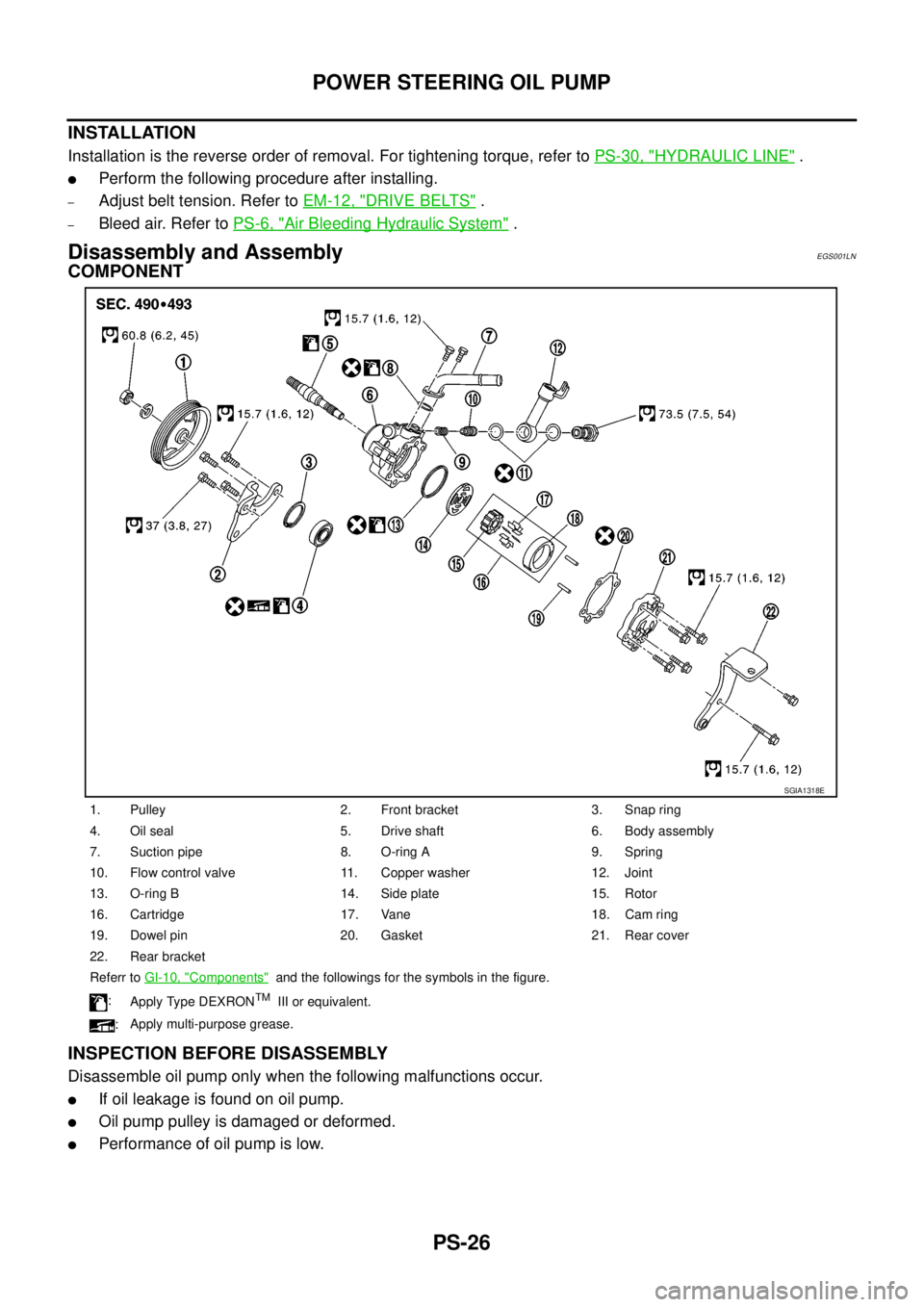
COMPONENT
INSPECTION BEFORE DISASSEMBLY
Disassemble oil pump only when the following malfunctions occur.
lIf oil leakage is found on oil pump.
lOil pump pulley is damaged or deformed.
lPerformance of oil pump is low.
1. Pulley 2. Front bracket 3. Snap ring
4. Oil seal 5. Drive shaft 6. Body assembly
7. Suction pipe 8. O-ring A 9. Spring
10. Flow control valve 11. Copper washer 12. Joint
13. O-ring B 14. Side plate 15. Rotor
16. Cartridge 17. Vane 18. Cam ring
19. Dowel pin 20. Gasket 21. Rear cover
22. Rear bracket
Referr toGI-10, "
Components"and the followings for the symbols in the figure.
:
Apply Type DEXRON
TMIII or equivalent.
:Apply multi-purpose grease.
SGIA1318E