2005 NISSAN NAVARA body
[x] Cancel search: bodyPage 2654 of 3171
POWER STEERING OIL PUMP
PS-27
C
D
E
F
H
I
J
K
L
MA
B
PS
DISASSEMBLY
NOTE:
Secure oil pump in a vise if necessary.
CAUTION:
Use copper plates when securing in a vise.
1. Remove rear bracket mounting bolts, and then remove rear bracket from rear cover.
2. Remove rear cover mounting bolts, and then remove rear cover from body assembly.
3. Remove gasket from body assembly.
4. Remove dowel pin, cartridge and side plate from body assembly.
5. Remove pulley mounting nut and washer, then remove pulley from drive shaft.
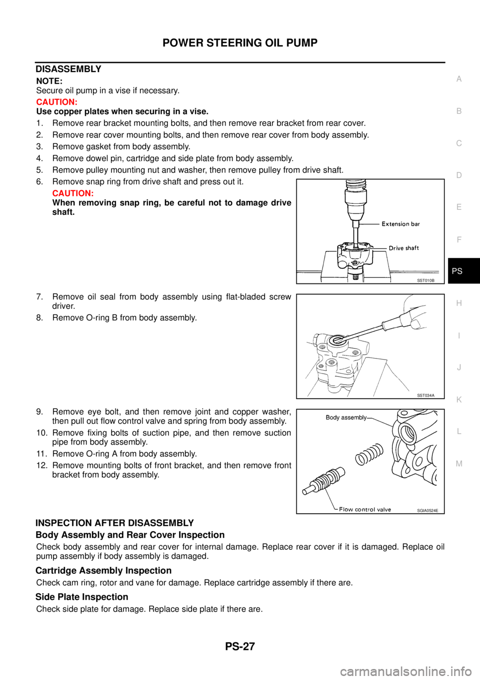
6. Remove snap ring from drive shaft and press out it.
CAUTION:
When removing snap ring, be careful not to damage drive
shaft.
7. Remove oil seal from body assembly using flat-bladed screw
driver.
8. Remove O-ring B from body assembly.
9. Remove eye bolt, and then remove joint and copper washer,
then pull out flow control valve and spring from body assembly.
10. Remove fixing bolts of suction pipe, and then remove suction
pipe from body assembly.
11. Remove O-ring A from body assembly.
12. Remove mounting bolts of front bracket, and then remove front
bracket from body assembly.
INSPECTION AFTER DISASSEMBLY
Body Assembly and Rear Cover Inspection
Check body assembly and rear cover for internal damage. Replace rear cover if it is damaged. Replace oil
pump assembly if body assembly is damaged.
Cartridge Assembly Inspection
Check cam ring, rotor and vane for damage. Replace cartridge assembly if there are.
Side Plate Inspection
Check side plate for damage. Replace side plate if there are.
SST010B
SST034A
SGIA0524E
Page 2655 of 3171
PS-28
POWER STEERING OIL PUMP
Flow Control Valve Inspection
Check flow control valve and spring for damage. Replace if there are.
ASSEMBLY
NOTE:
Secureoilpumpinaviseifnecessary.
CAUTION:
Use copper plates when securing in a vise.
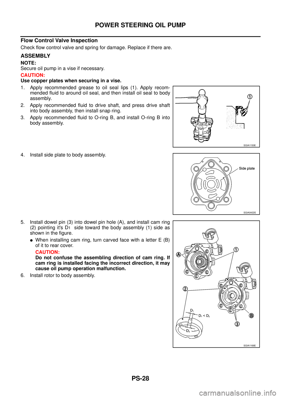
1. Apply recommended grease to oil seal lips (1). Apply recom-
mended fluid to around oil seal, and then install oil seal to body
assembly.
2. Apply recommended fluid to drive shaft, and press drive shaft
into body assembly, then install snap ring.
3. Apply recommended fluid to O-ring B, and install O-ring B into
body assembly.
4. Install side plate to body assembly.
5. Install dowel pin (3) into dowel pin hole (A), and install cam ring
(2) pointing it's D
1side toward the body assembly (1) side as
showninthefigure.
lWhen installing cam ring, turn carved face with a letter E (B)
of it to rear cover.
CAUTION:
Do not confuse the assembling direction of cam ring. If
cam ring is installed facing the incorrect direction, it may
cause oil pump operation malfunction.
6. Install rotor to body assembly.
SGIA1150E
SGIA0422E
SGIA1166E
Page 2656 of 3171
POWER STEERING OIL PUMP
PS-29
C
D
E
F
H
I
J
K
L
MA
B
PS
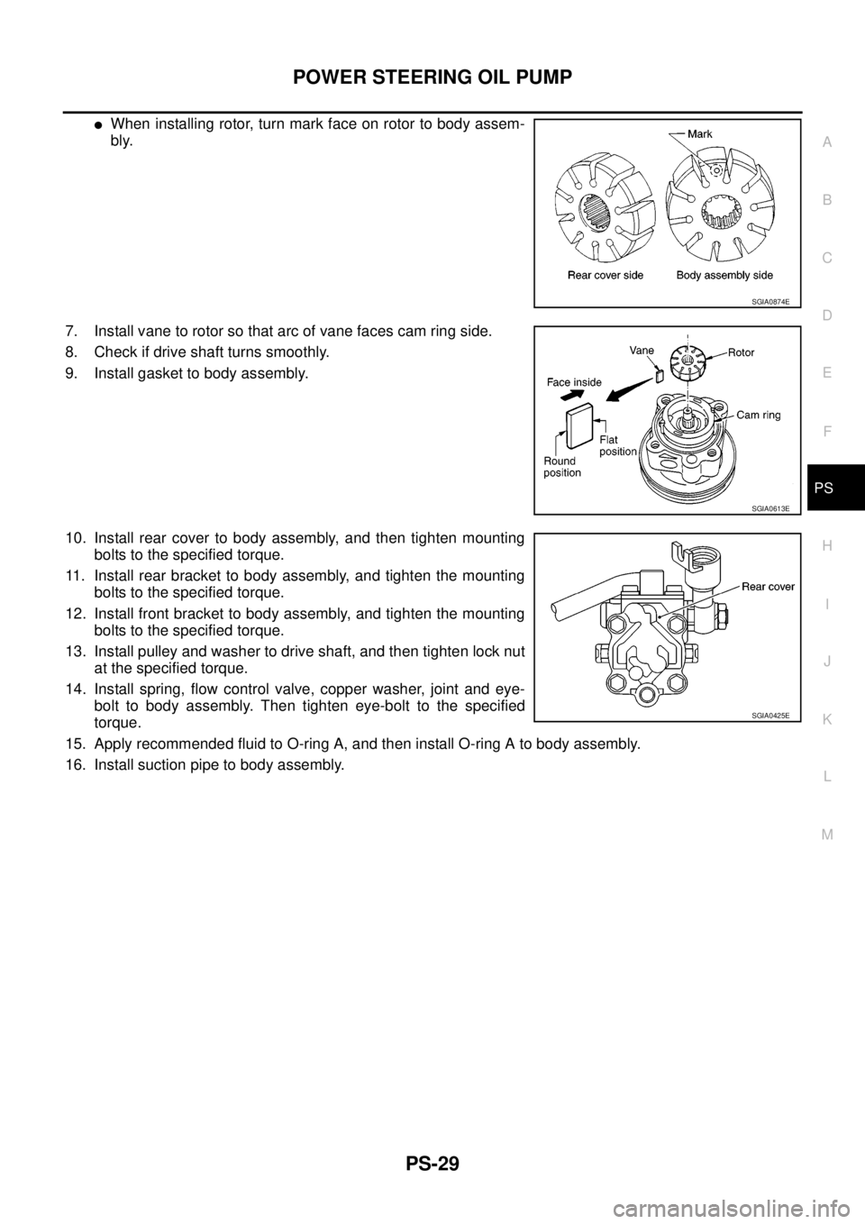
lWhen installing rotor, turn mark face on rotor to body assem-
bly.
7. Install vane to rotor so that arc of vane faces cam ring side.
8. Check if drive shaft turns smoothly.
9. Install gasket to body assembly.
10. Install rear cover to body assembly, and then tighten mounting
bolts to the specified torque.
11. Install rear bracket to body assembly, and tighten the mounting
bolts to the specified torque.
12. Install front bracket to body assembly, and tighten the mounting
bolts to the specified torque.
13. Install pulley and washer to drive shaft, and then tighten lock nut
at the specified torque.
14. Install spring, flow control valve, copper washer, joint and eye-
bolt to body assembly. Then tighten eye-bolt to the specified
torque.
15. Apply recommended fluid to O-ring A, and then install O-ring A to body assembly.
16. Install suction pipe to body assembly.
SGIA0874E
SGIA0613E
SGIA0425E
Page 2678 of 3171
RF-1
ROOF
IBODY
CONTENTS
C
D
E
F
G
H
J
K
L
M
SECTIONRF
A
B
RF
ROOF
PRECAUTIONS .......................................................... 2
Precautions for Supplemental Restraint System
(SRS)“AIRBAG”and“SEATBELTPRE-TEN-
SIONER” .................................................................. 2
Precautions .............................................................. 2
PREPARATION ........................................................... 3
Commercial Service Tool ......................................... 3
SQUEAK AND RATTLE TROUBLE DIAGNOSES..... 4
Work Flow ................................................................ 4
CUSTOMER INTERVIEW ..................................... 4
DUPLICATE THE NOISE AND TEST DRIVE ....... 5
CHECK RELATED SERVICE BULLETINS ........... 5
LOCATE THE NOISE AND IDENTIFY THE
ROOT CAUSE ...................................................... 5
REPAIR THE CAUSE ........................................... 5
CONFIRM THE REPAIR ....................................... 6
Generic Squeak and Rattle Troubleshooting ........... 6
INSTRUMENT PANEL .......................................... 6
CENTER CONSOLE ............................................. 6
DOORS ................................................................. 6
TRUNK .................................................................. 7
SUNROOF/HEADLINING ..................................... 7
SEATS ................................................................... 7
UNDERHOOD ....................................................... 7
Diagnostic Worksheet .............................................. 8
SUNROOF ................................................................ 10
Component Parts and Harness Connector Location... 10
System Description ................................................. 11
TILT UP / SLIDE CLOSE OPERATION ................ 11
TILT DOWN / SLIDE OPEN OPERATION ........... 11AUTO OPERATION ............................................. 11
ANTI-PINCH FUNCTION .................................... 11
MEMORY RESET PROCEDURE ....................... 12
INITIALIZATION PROCEDURE .......................... 12
CAN Communication System Description .............. 13
CAN Communication Unit ....................................... 13
Wiring Diagram — SROOF — ................................ 14
Terminals and Reference Value for BCM ............... 15
Terminals and Reference Value for Sunroof Motor
Assembly ................................................................ 15
Work Flow ............................................................... 16
Trouble Diagnosis Symptom Chart ......................... 16
BCM Power Supply and Ground Circuit Check ...... 16
Sunroof Motor Assembly Power Supply and Ground
Circuit Check .......................................................... 17
Sunroof Switch System Check ............................... 18
Fitting Adjustment ................................................... 20
GAP ADJUSTMENT ............................................ 20
HEIGHT DIFFERENCE ADJUSTMENT .............. 20
Removal and Installation ........................................ 21
SUNROOF UNIT ................................................. 22
GLASS LID .......................................................... 22
WIND DEFLECTOR ............................................ 23
SUNSHADE ........................................................ 23
SUNROOF MOTOR ............................................ 23
DRAIN HOSES .................................................... 25
WEATHERSTRIP ................................................ 25
REAR DRAIN ASSEMBLY .................................. 25
LINK AND WIRE ASSEMBLY ............................. 26
Page 2682 of 3171
SQUEAK AND RATTLE TROUBLE DIAGNOSES
RF-5
C
D
E
F
G
H
J
K
L
MA
B
RF
DUPLICATE THE NOISE AND TEST DRIVE
If possible, drive the vehicle with the customer until the noise is duplicated. Note any additional information on
the Diagnostic Worksheet regarding the conditions or location of the noise. This information can be used to
duplicate the same conditions when you confirm the repair.
If the noise can be duplicated easily during the test drive, to help identify the source of the noise, try to dupli-
cate the noise with the vehicle stopped by doing one or all of the following:
1) Close a door.
2) Tap or push/pull around the area where the noise appears to be coming from.
3) Rev the engine.
4) Use a floor jack to recreate vehicle “twist”.
5) At idle, apply engine load (electrical load, half-clutch on M/T models, drive position on A/T models).
6) Raisethevehicleonahoistandhitatirewitharubberhammer.
lDrive the vehicle and attempt to duplicate the conditions the customer states exist when the noise occurs.
lIf it is difficult to duplicate the noise, drive the vehicle slowly on an undulating or rough road to stress the
vehicle body.
CHECK RELATED SERVICE BULLETINS
After verifying the customer concern or symptom, check ASIST for Technical Service Bulletins (TSBs) related
to that concern or symptom.
If a TSB relates to the symptom, follow the procedure to repair the noise.
LOCATE THE NOISE AND IDENTIFY THE ROOT CAUSE
1. Narrow down the noise to a general area. To help pinpoint the source of the noise, use a listening tool
(Engine Ear or mechanics stethoscope).
2. Narrow down the noise to a more specific area and identify the cause of the noise by:
lremoving the components in the area that you suspect the noise is coming from.
Do not use too much force when removing clips and fasteners, otherwise clips and fastener can be broken
or lost during the repair, resulting in the creation of new noise.
ltapping or pushing/pulling the component that you suspect is causing the noise.
Do not tap or push/pull the component with excessive force, otherwise the noise will be eliminated only
temporarily.
lfeeling for a vibration with your hand by touching the component(s) that you suspect is (are) causing the
noise.
lplacing a piece of paper between components that you suspect are causing the noise.
llooking for loose components and contact marks.
Refer toRF-6, "
Generic Squeak and Rattle Troubleshooting".
REPAIR THE CAUSE
lIf the cause is a loose component, tighten the component securely.
lIf the cause is insufficient clearance between components:
–separate components by repositioning or loosening and retightening the component, if possible.
–insulate components with a suitable insulator such as urethane pads, foam blocks, felt cloth tape or ure-
thane tape are available through your authorized Nissan Parts Department.
CAUTION:
Do not use excessive force as many components are constructed of plastic and may be damaged.
NOTE:
Always check with the Parts Department for the latest parts information.
Each item can be ordered separately as needed.
URETHANE PADS [1.5 mm (0.059 in) thick]
Insulates connectors, harness, etc.
76268-9E005: 100´135 mm (3.94´5.31 in)/76884-71L01: 60´85 mm (2.36´3.35 in)/76884-71L02: 15´
25 mm (0.59´0.98 in)
INSULATOR (Foam blocks)
Insulates components from contact. Can be used to fill space behind a panel.
73982-9E000: 45 mm (1.77 in) thick, 50´50 mm (1.97´1.97 in)/73982-50Y00: 10 mm (0.39 in) thick, 50
´50 mm (1.97´1.97 in)
INSULATOR (Light foam block)
80845-71L00: 30 mm (1.18 in) thick, 30´50 mm (1.18´1.97 in)
Page 2688 of 3171
SUNROOF
RF-11
C
D
E
F
G
H
J
K
L
MA
B
RF
System DescriptionEIS00D4W
Power supplied at all time
lthrough 50A fusible link (letterG, located in the fuse and fusible link box)
lto BCM terminal 57.
lthrough 10A fuse [No.21, located in the fuse block (J/B)]
lto BCM terminal 41.
lthrough BCM terminal 58
lto sunroof motor assembly terminal 7.
Ground is supplied
lto BCM terminal 55
lthrough body grounds M21, M80 and M83.
lto sunroof motor assembly terminal 10
lthrough body grounds B9 and B25.
When ignition switch ON or START position,
Power is supplied
lthrough 10A fuse [No.1, located in the fuse block (J/B)]
lto BCM terminal 3.
lthrough BCM terminal 53
lto sunroof motor assembly terminal 9.
TILT UP / SLIDE CLOSE OPERATION
When tilt up / slide close switch is pressed,
Ground is supplied
lto sunroof motor assembly terminal 1
lthrough sunroof switch terminal 3
lthrough sunroof switch terminal 2
lthrough body grounds M21, M80 and M83.
Then, the sunroof tilt up / slide close.
TILT DOWN / SLIDE OPEN OPERATION
When tilt down / slide open switch is pressed,
Ground is supplied
lto sunroof motor assembly terminal 5
lthrough sunroof switch terminal 1
lthrough sunroof switch terminal 2
lthrough body grounds M21, M80 and M83.
Then, the sunroof tilt down / slide open.
AUTO OPERATION
The power sunroof AUTO feature makes it possible to slide open and slide close or tilt up and tilt down the
sunroof without holding the sunroof switch in the TILT UP/SLIDE CLOSE, TILT DOWN/SLIDE OPEN position.
ANTI-PINCH FUNCTION
The CPU of sunroof motor assembly monitors the sunroof motor operation and the sunroof position (fully-
closed or other) by the signals from sunroof motor.
When sunroof motor detects an interruption during the following slide close and tilt down operation, sunroof
switch controls the motor for open and the sunroof will operate until it reaches full up position (when tilt down
operate) or 125 mm (4.92 in) or more in an open direction (during slide close operate).
lclose operation and tilt down when ignition switch is in the ON position.
Page 2823 of 3171
SB-6
SEAT BELTS
REMOVALOFSEATBELTRETRACTOR
CAUTION:
lBefore servicing SRS, turn the ignition switch off, disconnect both battery cables and wait at least
3 minutes.
1. Remove the center pillar upper/lower finishers. Refer toEI-33, "
BODY SIDE TRIM".
2. Remove the seat belt retractor and belt bolts and assembly.
lOn RH side, disconnect the seat belt tension sensor.
3. Disconnect the seat belt pre-tensioner electrical connector.
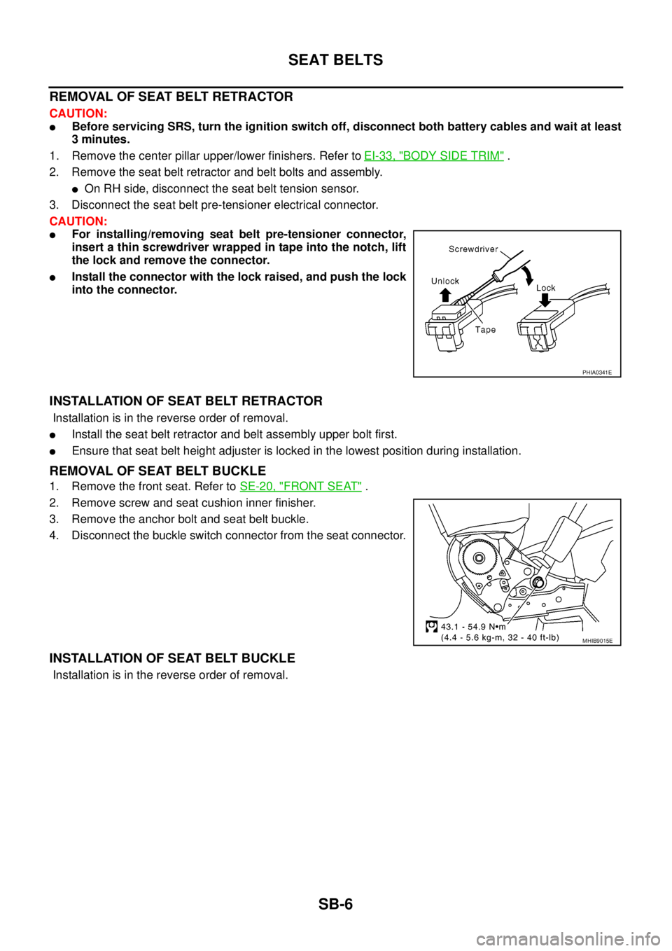
CAUTION:
lFor installing/removing seat belt pre-tensioner connector,
insert a thin screwdriver wrapped in tape into the notch, lift
the lock and remove the connector.
lInstall the connector with the lock raised, and push the lock
into the connector.
INSTALLATION OF SEAT BELT RETRACTOR
Installation is in the reverse order of removal.
lInstall the seat belt retractor and belt assembly upper bolt first.
lEnsure that seat belt height adjuster is locked in the lowest position during installation.
REMOVAL OF SEAT BELT BUCKLE
1. Remove the front seat. Refer toSE-20, "FRONT SEAT".
2. Remove screw and seat cushion inner finisher.
3. Remove the anchor bolt and seat belt buckle.
4. Disconnect the buckle switch connector from the seat connector.
INSTALLATION OF SEAT BELT BUCKLE
Installation is in the reverse order of removal.
PHIA0341E
MHIB9015E
Page 2825 of 3171
SB-8
SEAT BELTS
REMOVAL
1. Remove seat belt lower anchor cover and bolt.
2. Remove the D-ring anchor bolt cover and D-ring anchor bolt.
3. Remove the upper and lower rear pillar finishers. Refer toEI-33, "
BODY SIDE TRIM".
4. Remove seat belt retractor and belt assembly bolt.
INSTALLATION
Installation is in the reverse order of removal.
REMOVAL OF SEAT BELT BUCKLE
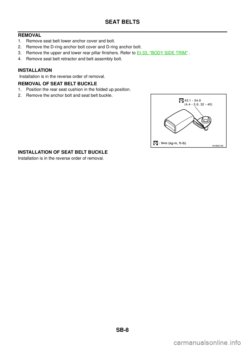
1. Position the rear seat cushion in the folded up position.
2. Remove the anchor bolt and seat belt buckle.
INSTALLATION OF SEAT BELT BUCKLE
Installation is in the reverse order of removal.
MHIB9019E