2005 NISSAN NAVARA body
[x] Cancel search: bodyPage 2311 of 3171
MA-36
CHASSIS AND BODY MAINTENANCE
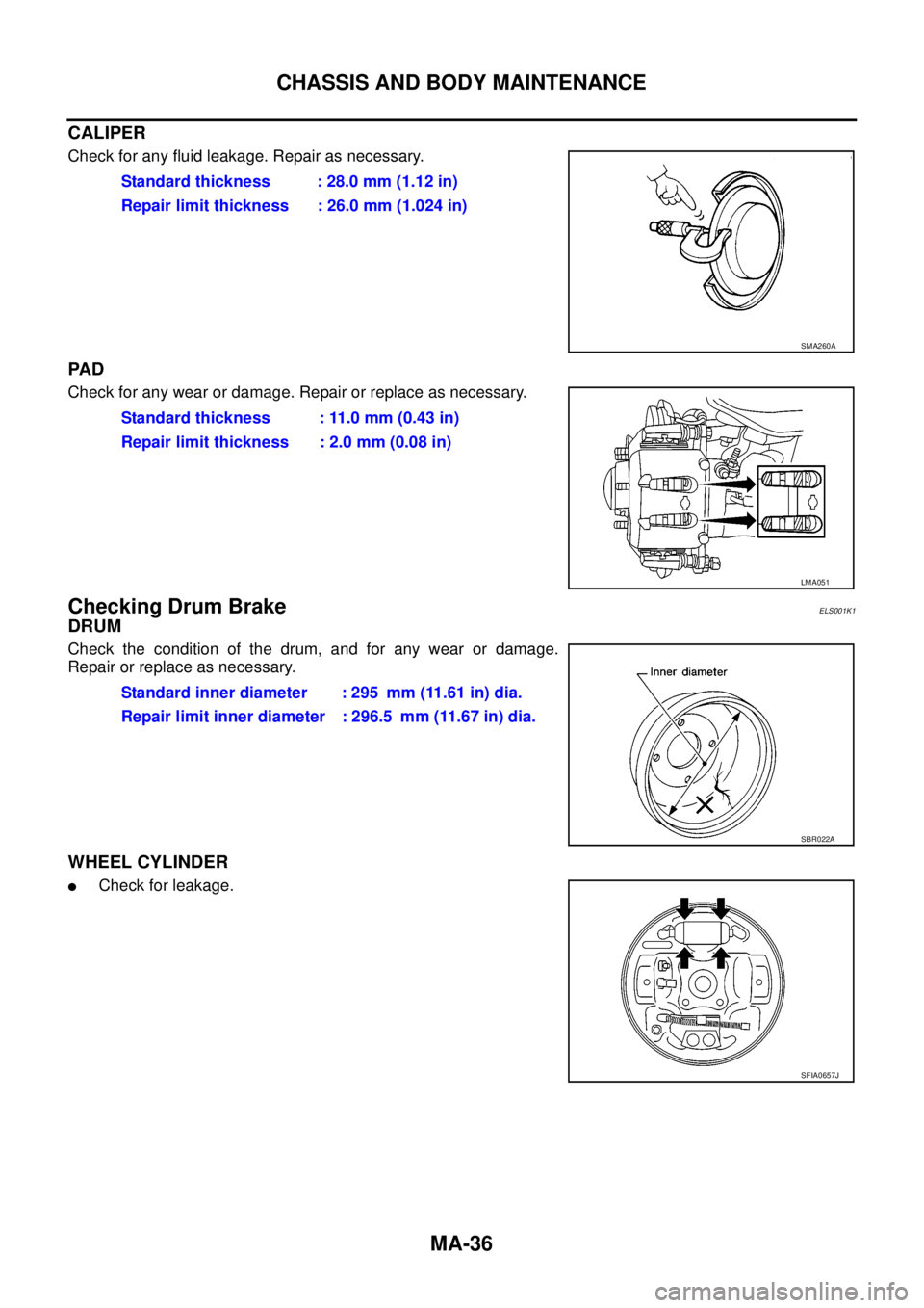
CALIPER
Check for any fluid leakage. Repair as necessary.
PA D
Check for any wear or damage. Repair or replace as necessary.
Checking Drum BrakeELS001K1
DRUM
Check the condition of the drum, and for any wear or damage.
Repair or replace as necessary.
WHEEL CYLINDER
lCheck for leakage.Standard thickness : 28.0 mm (1.12 in)
Repair limit thickness : 26.0 mm (1.024 in)
SMA260A
Standard thickness : 11.0 mm (0.43 in)
Repair limit thickness : 2.0 mm (0.08 in)
LMA051
Standard inner diameter : 295 mm (11.61 in) dia.
Repair limit inner diameter : 296.5 mm (11.67 in) dia.
SBR022A
SFIA0657J
Page 2312 of 3171
CHASSIS AND BODY MAINTENANCE
MA-37
C
D
E
F
G
H
I
J
K
MA
B
MA
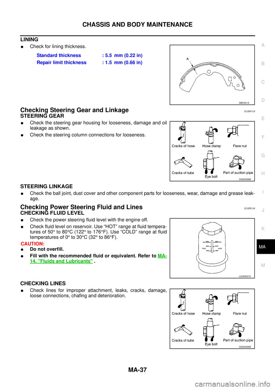
LINING
lCheck for lining thickness.
Checking Steering Gear and LinkageELS001J3
STEERING GEAR
lCheck the steering gear housing for looseness, damage and oil
leakage as shown.
lCheck the steering column connections for looseness.
STEERING LINKAGE
lCheck the ball joint, dust cover and other component parts for looseness, wear, damage and grease leak-
age.
Checking Power Steering Fluid and LinesELS001J4
CHECKING FLUID LEVEL
lCheck the power steering fluid level with the engine off.
lCheck fluid level on reservoir. Use “HOT” range at fluid tempera-
tures of 50°to 80°C(122°to 176°F). Use “COLD” range at fluid
temperatures of 0°to 30°C(32°to 86°F).
CAUTION:
lDo not overfill.
lFill with the recommended fluid or equivalent. Refer toMA-
14, "Fluids and Lubricants".
CHECKING LINES
lCheck lines for improper attachment, leaks, cracks, damage,
loose connections, chafing and deterioration.Standard thickness : 5.5 mm (0.22 in)
Repair limit thickness : 1.5 mm (0.66 in)
SBR021A
SGIA0506E
LGIA0021E
SGIA0506E
Page 2313 of 3171
MA-38
CHASSIS AND BODY MAINTENANCE
Checking Axle and Suspension Parts
ELS001J5
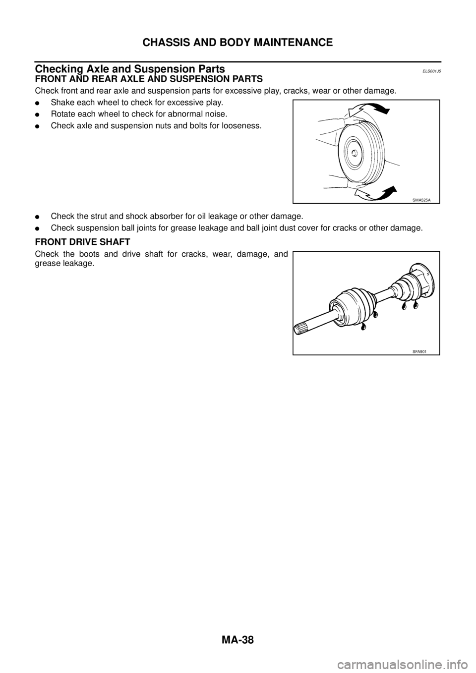
FRONT AND REAR AXLE AND SUSPENSION PARTS
Check front and rear axle and suspension parts for excessive play, cracks, wear or other damage.
lShake each wheel to check for excessive play.
lRotate each wheel to check for abnormal noise.
lCheck axle and suspension nuts and bolts for looseness.
lCheck the strut and shock absorber for oil leakage or other damage.
lCheck suspension ball joints for grease leakage and ball joint dust cover for cracks or other damage.
FRONT DRIVE SHAFT
Check the boots and drive shaft for cracks, wear, damage, and
grease leakage.
SMA525A
SFA901
Page 2314 of 3171
CHASSIS AND BODY MAINTENANCE
MA-39
C
D
E
F
G
H
I
J
K
MA
B
MA
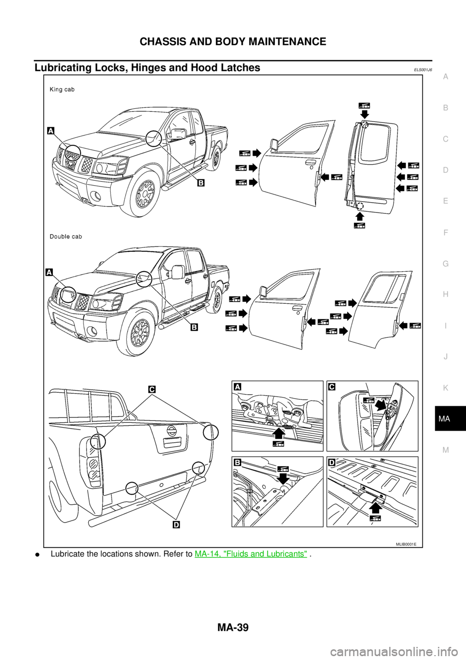
Lubricating Locks, Hinges and Hood LatchesELS001J6
lLubricate the locations shown. Refer toMA-14, "Fluids and Lubricants".
MLIB0001E
Page 2315 of 3171
MA-40
CHASSIS AND BODY MAINTENANCE
Checking Seat Belts, Buckles, Retractors, Anchors and Adjusters
ELS001J7
Check the seat belt buckles, webbing, retractors, anchors and adjusters. Replace any seat belt assembly as
necessary. Refer toSB-11, "
Seat Belt Inspection".
lCheck the seat belt anchors for loose mounting bolts, damage, or excessive wear.
lCheck the seat belt webbing for any damage, cuts, fraying, or excessive wear.
lCheck the retractor for smooth operation.
lCheck the function of the buckles by inserting the seat belt tongue and checking for proper engagement of
the buckle and press the button on the buckle to check for proper release of the seat belt tongue.
CAUTION:
lAfter any collision, inspect all seat belt assemblies, including retractors and other attached com-
ponents, such as the guide rail set. NISSAN recommends replacing all seat belt assemblies in use
during a collision, unless they are not damaged and are inspected to confirm they are operating
properly after a minor collision.
Also inspect all seat belt assemblies that are not in use during a collision, and replace any compo-
nents if damaged or not operating properly. The seat belt pre-tensioner should be replaced even if
the seat belts are not in use during a frontal collision where the driver and passenger air bags
have been deployed.
lIf any component of the seat belt assembly is suspected of being damaged or not operating prop-
erly, do not repair the component. Replace the components as an assembly.
lIf the seat belt webbing is cut, frayed, or damaged then replace the seat belt assembly.
lNever lubricate the seat belt buckle or tongue.
lWhen replacing any seat belt assembly always use a Genuine NISSAN seat belt assembly.
Checking Body CorrosionELS001K3
Visually check body panels for collision damage (scratches, chipping, rubbing, etc.) or damage to the anti-cor-
rosion materials. In particular, check the following locations.
HEMMED PANELS
Hood front end, door lower end, trunk lid rear end, etc.
PANEL JOINT
Side sill of rear fender and center pillar, rear wheel housing of rear fender, around strut tower in engine com-
partment, etc.
PANEL EDGE
Trunk lid opening, sunroof opening, fender wheel-arch flange, fuel filler lid flange, around holes in panel, etc.
PARTS CONTACT
Waist moulding, windshield moulding, bumper, etc.
PROTECTORS
Damage or condition of mudguard, fender protector, chipping protector, etc.
ANTI-CORROSION MATERIALS
Damage or separation of anti-corrosion materials under the body.
DRAIN HOLES
Condition of drain holes at door and side sill. When repairing corroded areas, refer to the Corrosion Repair
Manual.
Page 2402 of 3171
PRECAUTIONS
MTC-15
C
D
E
F
G
H
I
K
L
MA
B
MTC
lA compressor shaft seal should not be repaired because of dye seepage. The compressor shaft seal
should only be repaired after confirming the leak with an electronic refrigerant leak detector (J-41995).
lAlways remove any remaining dye from the leak area after repairs are complete to avoid a misdiagnosis
during a future service.
lDo not allow dye to come into contact with painted body panels or interior components. If dye is spilled,
clean immediately with the approved dye cleaner. Fluorescent dye left on a surface for an extended period
of time cannot be removed.
lDo not spray the fluorescent dye cleaning agent on hot surfaces (engine exhaust manifold, etc.).
lDo not use more than one refrigerant dye bottle (1/4 ounce /7.4 cc) per A/C system.
lLeak detection dyes for HFC-134a (R-134a) and CFC-12 (R-12) A/C systems are different. Do not use
HFC-134a (R-134a) leak detection dye in CFC-12 (R-12) A/C system or CFC-12 (R-12) leak detector dye
in HFC-134a (R-134a) A/C systems or A/C system damage may result.
lThe fluorescent properties of the dye will remain for over three (3) years unless a compressor malfunction
occurs.
IDENTIFICATION
NOTE:
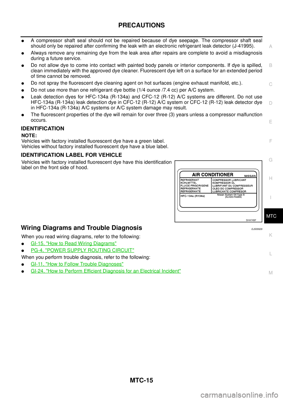
Vehicles with factory installed fluorescent dye have a green label.
Vehicles without factory installed fluorescent dye have a blue label.
IDENTIFICATION LABEL FOR VEHICLE
Vehicles with factory installed fluorescent dye have this identification
label on the front side of hood.
Wiring Diagrams and Trouble DiagnosisEJS00626
When you read wiring diagrams, refer to the following:
lGI-15, "How to Read Wiring Diagrams"
lPG-4, "POWER SUPPLY ROUTING CIRCUIT"
When you perform trouble diagnosis, refer to the following:
lGI-11, "How to Follow Trouble Diagnoses"
lGI-24, "How to Perform Efficient Diagnosis for an Electrical Incident"
SHA749F
Page 2492 of 3171
HEATER & COOLING UNIT ASSEMBLY
MTC-105
C
D
E
F
G
H
I
K
L
MA
B
MTC
Removal and InstallationEJS005GY
REMOVAL
1. Discharge the refrigerant from the A/C system. Refer toMTC-118, "Discharging Refrigerant".
2. Drain the coolant from the engine cooling system. Refer toCO-8, "
DRAINING ENGINE COOLANT".
3. Remove the cowl top extension. Refer toEI-20, "
Removal and Installation".
4. Remove the exhaust system. Refer toEX-3, "
Removal and Installation".
5. Disconnect the heater hoses from the heater core.
6. Disconnect the high/low pressure pipes from the expansion valve.
7. Move the two front seats to the rearmost position on the seat track.
8. Remove the instrument panel and console panel. Refer toIP-10, "
Removal and Installation".
9. Remove the steering column. Refer toPS-11, "
Removal and Installation".
10. Disconnect the instrument panel wire harness at the RH and LH in-line connector brackets, and the fuse
block (J/B) electrical connectors. Refer toPG-38, "
Harness Layout".
11. Disconnect the steering member from each side of the vehicle body.
12. Remove the heater and cooling unit assembly with it attached to the steering member, from the vehicle.
CAUTION:
Use care not to damage the seats and interior trim panels when removing the heater and cooling
unit assembly with it attached to the steering member.
13. Remove the heater and cooling unit assembly from the steering member.
INSTALLATION
Installation is in the reverse order of removal.
CAUTION:
lReplace the O-ring of the low-pressure pipe and high-pressure pipe with a new one, and apply
compressor oil to it when installing it.
lAfter charging the refrigerant, check for leaks.
NOTE:
lFill the engine cooling system with the specified coolant mixture. Refer toCO-8, "REFILLING ENGINE
COOLANT".
lRecharge the A/C system. Refer toMTC-118, "Evacuating System and Charging Refrigerant".
Page 2530 of 3171
PG-1
POWER SUPPLY, GROUND & CIRCUIT ELEMENTS
K ELECTRICAL
CONTENTS
C
D
E
F
G
H
I
J
L
M
SECTIONPG
A
B
PG
POWER SUPPLY, GROUND & CIRCUIT ELEMENTS
PRECAUTIONS .......................................................... 3
Precautions for Supplemental Restraint System
(SRS)“AIRBAG”and“SEATBELTPRE-TEN-
SIONER” .................................................................. 3
Wiring Diagrams and Trouble Diagnosis .................. 3
POWER SUPPLY ROUTING CIRCUIT ...................... 4
Schematic ................................................................ 4
Wiring Diagram — POWER — ................................. 5
BATTERY POWER SUPPLY — IGNITION SW.
IN ANY POSITION ................................................ 5
ACCESSORY POWER SUPPLY — IGNITION
SW. IN ACC OR ON ............................................ 10
IGNITION POWER SUPPLY — IGNITION SW.
IN ON ................................................................... 11
IGNITION POWER SUPPLY — IGNITION SW.
IN ON AND/OR START ....................................... 12
IPDM E/R (INTELLIGENT POWER DISTRIBUTION
MODULE ENGINE ROOM) ...................................... 14
System Description ................................................ 14
SYSTEMS CONTROLLED BY IPDM E/R ........... 14
CAN COMMUNICATION LINE CONTROL ......... 14
IPDM E/R STATUS CONTROL ........................... 15
CAN Communication System Description .............. 15
Function of Detecting Ignition Relay Malfunction ... 15
CONSULT-II Function (IPDM E/R) ......................... 16
CONSULT-II BASIC OPERATION ...................... 16
SELF-DIAGNOSTIC RESULTS .......................... 17
DATA MONITOR ................................................. 17
CAN DIAG SUPPORT MNTR ............................. 18
ACTIVE TEST ..................................................... 18
Auto Active Test ..................................................... 19
DESCRIPTION .................................................... 19
OPERATION PROCEDURE ............................... 19
INSPECTION IN AUTO ACTIVE TEST MODE... 20
Schematic .............................................................. 22
IPDM E/R Terminal Arrangement ........................... 23
Check IPDM E/R Power Supply and Ground Circuit... 24Inspection with CONSULT-II (Self-Diagnosis) ........ 25
Removal and Installation of IPDM E/R ................... 26
REMOVAL ........................................................... 26
INSTALLATION ................................................... 26
GROUND CIRCUIT ................................................... 27
Ground Distribution ................................................. 27
MAIN HARNESS ................................................. 27
ENGINE ROOM HARNESS ................................ 30
ENGINE CONTROL HARNESS .......................... 34
BODY HARNESS (LH SIDE) .............................. 35
BODY HARNESS (RH SIDE) .............................. 36
DEFOGGER CABLE ........................................... 37
HARNESS ................................................................. 38
Harness Layout ...................................................... 38
HOW TO READ HARNESS LAYOUT ................. 38
OUTLINE/DOUBLE CAB MODELS .................... 39
OUTLINE/KING CAB MODELS .......................... 40
MAIN HARNESS/LHD MODELS ......................... 41
MAIN HARNESS/RHD MODELS ........................ 44
ENGINE ROOM HARNESS/LHD MODELS ........ 47
ENGINE ROOM HARNESS/RHD MODELS ....... 49
ENGINE CONTROL HARNESS .......................... 51
CHASSIS HARNESS .......................................... 53
BODY HARNESS (LH SIDE)/DOUBLE CAB
MODELS ............................................................. 54
BODY HARNESS (RH SIDE)/DOUBLE CAB
MODELS ............................................................. 56
BODY HARNESS (LH SIDE)/KING CAB MOD-
ELS ...................................................................... 58
BODY HARNESS (RH SIDE)/KING CAB MOD-
ELS ...................................................................... 60
ROOM LAMP HARNESS .................................... 62
FRONT DOOR LH HARNESS/LHD MODELS .... 63
FRONT DOOR RH HARNESS/LHD MODELS ... 63
FRONT DOOR LH HARNESS/RHD MODELS ... 64
FRONT DOOR RH HARNESS/RHD MODELS ... 64
REAR DOOR LH HARNESS/DOUBLE CAB
MODELS ............................................................. 65
REAR DOOR RH HARNESS/DOUBLE CAB
MODELS ............................................................. 65