2005 NISSAN NAVARA body
[x] Cancel search: bodyPage 1 of 3171
MODELD40 SERIES
2005 NISSAN EUROPE S.A.S.
All rights reserved. No part of this Electronic Service Manual may be reproduced or stored in a retrieval system, or transmitted in any
form, or by any means, electronic, mechanical, photocopying, recording or otherwise, without the prior written permission of Nissan
Europe S.A.S., Paris, France.
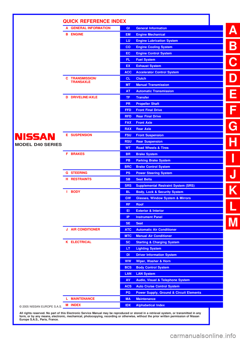
A GENERAL INFORMATION
B ENGINE
C TRANSMISSION/TRANSAXLE
D DRIVELINE/AXLE
E SUSPENSION F BRAKES
G STEERING H RESTRAINTS
I BODY
J AIR CONDITIONER
K ELECTRICAL
L MAINTENANCE
M INDEXGI General Information
EM Engine Mechanical
LU Engine Lubrication System
CO Engine Cooling System
EC Engine Control System
FL Fuel System
EX Exhaust System
ACC Accelerator Control System
CL Clutch
MTManualTransmission
AT Automatic Transmission
TF Transfer
PR Propeller Shaft
FFD Front Final Drive
RFD Rear Final Drive
FAX Front Axle
RAX Rear Axle
FSU Front Suspension
RSU Rear Suspension
WT Road Wheels & Tires
BR Brake System
PB Parking Brake System
BRC Brake Control System
PS Power Steering System
SB Seat Belts
SRS Supplemental Restraint System (SRS)
BL Body, Lock & Security System
GW Glasses, Window System & Mirrors
RF Roof
EI Exterior & Interior
IP Instrument Panel
SE Seat
ATC Automatic Air Conditioner
MTC Manual Air Conditioner
SC Starting & Charging System
LT Lighting System
DI Driver Information System
WW Wiper, Washer & Horn
BCS Body Control System
LAN LAN System
AV Audio, Visual & Telephone System
ACS Auto Cruise Control System
PG Power Supply, Ground & Circuit Elements
MA Maintenance
IDX Alphabetical Index
QUICK REFERENCE INDEX
A
B
C
D
E
F
G
H
I
J
K
L
M
Page 15 of 3171
PRECAUTIONS
AT-7
D
E
F
G
H
I
J
K
L
MA
B
AT
PRECAUTIONSPFP:00001
Precautions for Supplemental Restraint System (SRS) “AIR BAG” and “SEAT
BELT PRE-TENSIONER”
ECS00IPT
The Supplemental Restraint System such as “AIR BAG” and “SEAT BELT PRE-TENSIONER”, used along
with a front seat belt, helps to reduce the risk or severity of injury to the driver and front passenger for certain
types of collision. Information necessary to service the system safely is included in the SRS and SB section of
this Service Manual.
WARNING:
lTo avoid rendering the SRS inoperative, which could increase the risk of personal injury or death
in the event of a collision which would result in air bag inflation, all maintenance must be per-
formed by an authorized NISSAN/INFINITI dealer.
lImproper maintenance, including incorrect removal and installation of the SRS, can lead to per-
sonal injury caused by unintentional activation of the system. For removal of Spiral Cable and Air
Bag Module, see the SRS section.
lDo not use electrical test equipment on any circuit related to the SRS unless instructed to in this
Service Manual. SRS wiring harnesses can be identified by yellow and/or orange harnesses or
harness connectors.
PrecautionsECS00IPR
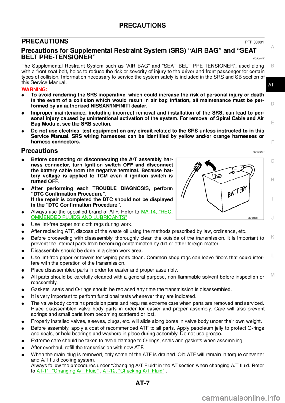
lBefore connecting or disconnecting the A/T assembly har-
ness connector, turn ignition switch OFF and disconnect
the battery cable from the negative terminal. Because bat-
tery voltage is applied to TCM even if ignition switch is
turned OFF.
lAfter performing each TROUBLE DIAGNOSIS, perform
“DTC Confirmation Procedure”.
If the repair is completed the DTC should not be displayed
in the “DTC Confirmation Procedure”.
lAlways use the specified brand of ATF. Refer toMA-14, "REC-
OMMENDED FLUIDS AND LUBRICANTS".
lUse lint-free paper not cloth rags during work.
lAfter replacing ATF, dispose of the waste oil using the methods prescribed by law, ordinance, etc.
lBefore proceeding with disassembly, thoroughly clean the outside of the transmission. It is important to
prevent the internal parts from becoming contaminated by dirt or other foreign matter.
lDisassembly should be done in a clean work area.
lUse lint-free paper or towels for wiping parts clean. Common shop rags can leave fibers that could inter-
fere with the operation of the transmission.
lPlace disassembled parts in order for easier and proper assembly.
lAll parts should be carefully cleaned with a general purpose, non-flammable solvent before inspection or
reassembly.
lGaskets, seals and O-rings should be replaced any time the transmission is disassembled.
lIt is very important to perform functional tests whenever they are indicated.
lThe valve body contains precision parts and requires extreme care when parts are removed and serviced.
Place disassembled valve body parts in order for easier and proper assembly. Care will also prevent
springs and small parts from becoming scattered or lost.
lProperly installed valves, sleeves, plugs, etc. will slide along bores in valve body under their own weight.
lBefore assembly, apply a coat of recommended ATF to all parts. Apply petroleum jelly to protect O-rings
and seals, or hold bearings and washers in place during assembly. Do not use grease.
lExtreme care should be taken to avoid damage to O-rings, seals and gaskets when assembling.
lAfter overhaul, refill the transmission with new ATF.
lWhen the drain plug is removed, only some of the ATF is drained. Old ATF will remain in torque converter
and A/T fluid cooling system.
Always follow the procedures under “Changing A/T Fluid” in the AT section when changing A/T fluid. Refer
toAT-11, "
Changing A/T Fluid",AT-12, "Checking A/T Fluid".
SEF289H
Page 219 of 3171
SHIFT CONTROL SYSTEM
AT-211
D
E
F
G
H
I
J
K
L
MA
B
AT
Adjustment of A/T PositionECS00G2X
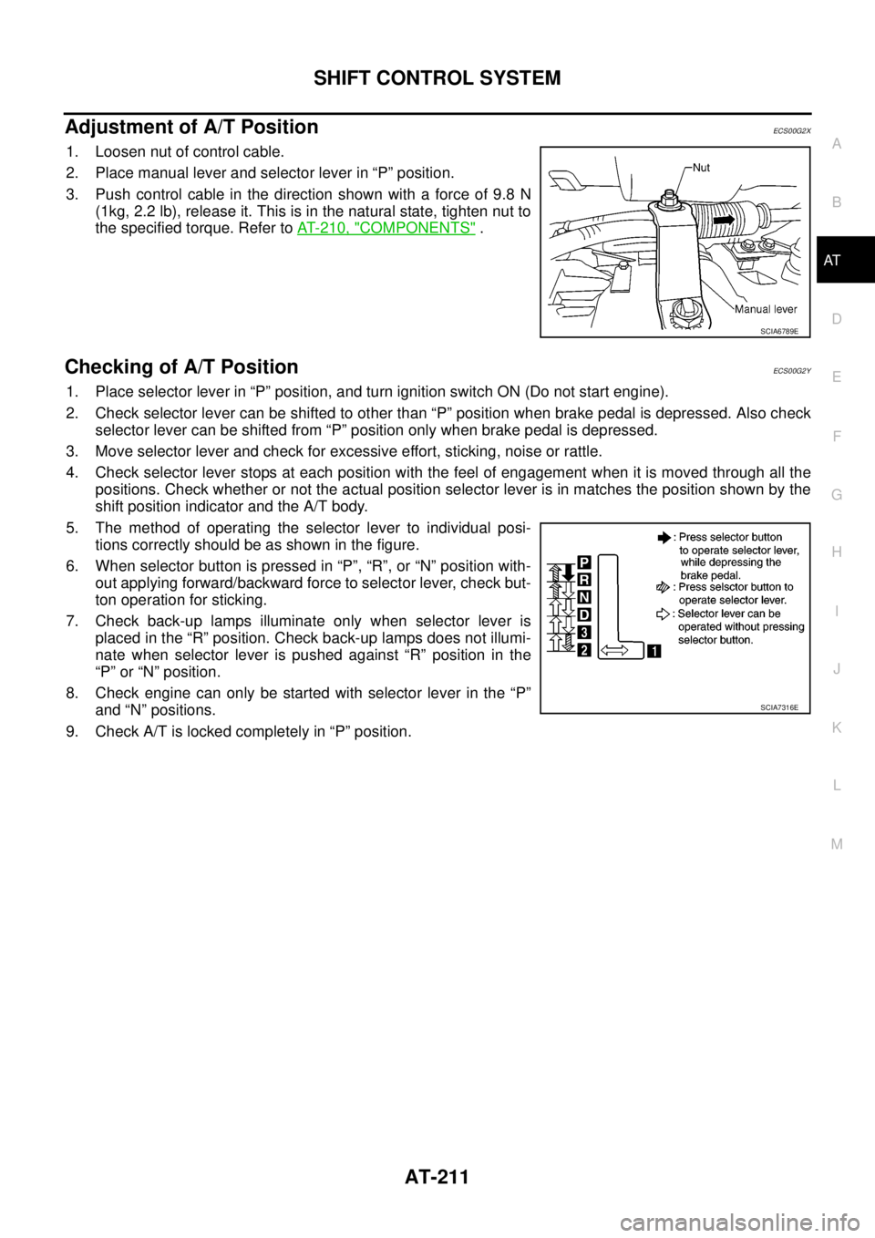
1. Loosen nut of control cable.
2. Place manual lever and selector lever in “P” position.
3. Push control cable in the direction shown with a force of 9.8 N
(1kg, 2.2 lb), release it. This is in the natural state, tighten nut to
the specified torque. Refer toAT- 2 1 0 , "
COMPONENTS".
Checking of A/T PositionECS00G2Y
1. Place selector lever in “P” position, and turn ignition switch ON (Do not start engine).
2. Check selector lever can be shifted to other than “P” position when brake pedal is depressed. Also check
selector lever can be shifted from “P” position only when brake pedal is depressed.
3. Move selector lever and check for excessive effort, sticking, noise or rattle.
4. Check selector lever stops at each position with the feel of engagement when it is moved through all the
positions. Check whether or not the actual position selector lever is in matches the position shown by the
shift position indicator and the A/T body.
5. The method of operating the selector lever to individual posi-
tions correctly should be as shown in the figure.
6. When selector button is pressed in “P”, “R”, or “N” position with-
out applying forward/backward force to selector lever, check but-
ton operation for sticking.
7. Check back-up lamps illuminate only when selector lever is
placed in the “R” position. Check back-up lamps does not illumi-
nate when selector lever is pushed against “R” position in the
“P” or “N” position.
8. Check engine can only be started with selector lever in the “P”
and “N” positions.
9. Check A/T is locked completely in “P” position.
SCIA6789E
SCIA7316E
Page 349 of 3171
PRECAUTIONS
ATC-15
C
D
E
F
G
H
I
K
L
MA
B
AT C
lA compressor shaft seal should not be repaired because of dye seepage. The compressor shaft seal
should only be repaired after confirming the leak with an electronic refrigerant leak detector (J-41995).
lAlways remove any remaining dye from the leak area after repairs are complete to avoid a misdiagnosis
during a future service.
lDo not allow dye to come into contact with painted body panels or interior components. If dye is spilled,
clean immediately with the approved dye cleaner. Fluorescent dye left on a surface for an extended period
of time cannot be removed.
lDo not spray the fluorescent dye cleaning agent on hot surfaces (engine exhaust manifold, etc.).
lDo not use more than one refrigerant dye bottle (1/4 ounce /7.4 cc) per A/C system.
lLeak detection dyes for HFC-134a (R-134a) and CFC-12 (R-12) A/C systems are different. Do not use
HFC-134a (R-134a) leak detection dye in CFC-12 (R-12) A/C system or CFC-12 (R-12) leak detector dye
in HFC-134a (R-134a) A/C systems or A/C system damage may result.
lThe fluorescent properties of the dye will remain for over three (3) years unless a compressor malfunction
occurs.
IDENTIFICATION
NOTE:
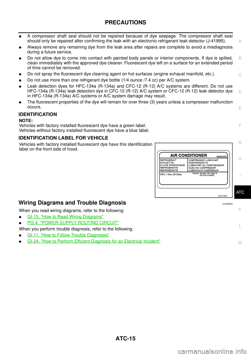
Vehicles with factory installed fluorescent dye have a green label.
Vehicles without factory installed fluorescent dye have a blue label.
IDENTIFICATION LABEL FOR VEHICLE
Vehicles with factory installed fluorescent dye have this identification
label on the front side of hood.
Wiring Diagrams and Trouble DiagnosisEJS006AS
When you read wiring diagrams, refer to the following:
lGI-15, "How to Read Wiring Diagrams"
lPG-4, "POWER SUPPLY ROUTING CIRCUIT"
When you perform trouble diagnosis, refer to the following:
lGI-11, "How to Follow Trouble Diagnoses"
lGI-24, "How to Perform Efficient Diagnosis for an Electrical Incident"
SHA749F
Page 456 of 3171
ATC-122
AIR CONDITIONER FILTER
AIR CONDITIONER FILTER
PFP:27277
Removal and InstallationEJS006C7
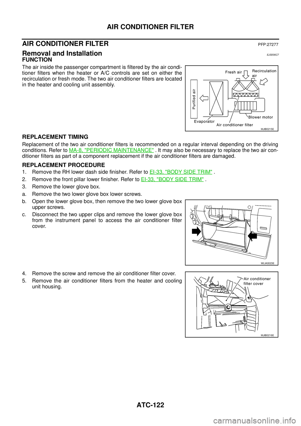
FUNCTION
The air inside the passenger compartment is filtered by the air condi-
tioner filters when the heater or A/C controls are set on either the
recirculation or fresh mode. The two air conditioner filters are located
in the heater and cooling unit assembly.
REPLACEMENT TIMING
Replacement of the two air conditioner filters is recommended on a regular interval depending on the driving
conditions. Refer toMA-8, "
PERIODIC MAINTENANCE". It may also be necessary to replace the two air con-
ditioner filters as part of a component replacement if the air conditioner filters are damaged.
REPLACEMENT PROCEDURE
1. Remove the RH lower dash side finisher. Refer toEI-33, "BODY SIDE TRIM".
2. Remove the front pillar lower finisher. Refer toEI-33, "
BODY SIDE TRIM".
3. Remove the lower glove box.
a. Remove the two lower glove box lower screws.
b. Open the lower glove box, then remove the two lower glove box
upper screws.
c. Disconnect the two upper clips and remove the lower glove box
from the instrument panel to access the air conditioner filter
cover.
4. Remove the screw and remove the air conditioner filter cover.
5. Remove the air conditioner filters from the heater and cooling
unit housing.
MJIB0215E
WLIA0023E
MJIB0216E
Page 460 of 3171
ATC-126
HEATER & COOLING UNIT ASSEMBLY
Removal and Installation
EJS006C9
REMOVAL
1. Discharge the refrigerant from the A/C system. Refer toATC-138, "Discharging Refrigerant".
2. Drain the coolant from the engine cooling system. Refer toCO-8, "
DRAINING ENGINE COOLANT".
3. Remove the heater core pipes RH nut.
4. Disconnect the heater core hoses from the heater core.
5. Disconnect the high- and low-pressure A/C pipes from the
expansion valve.
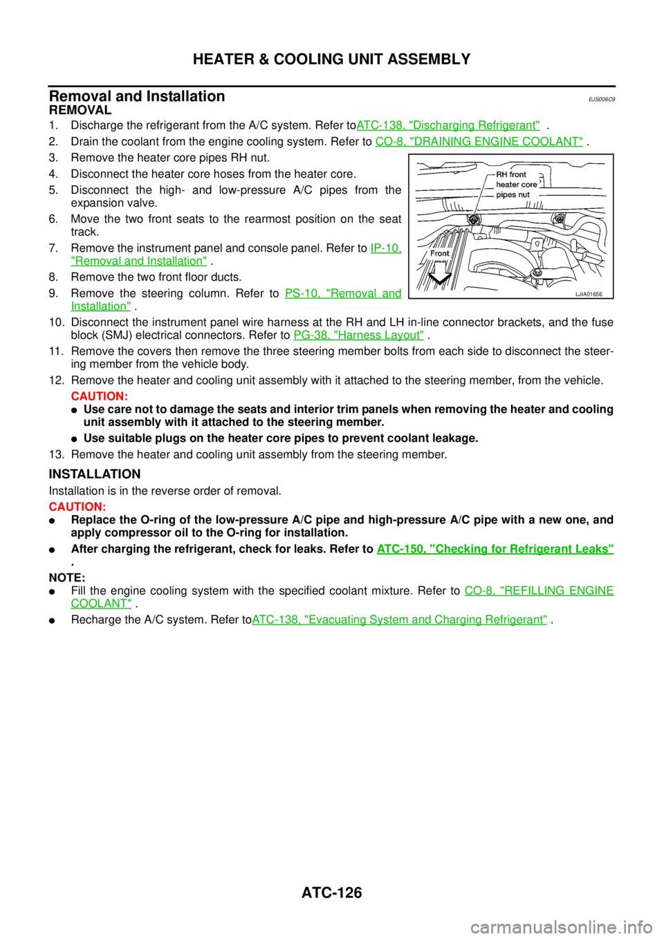
6. Move the two front seats to the rearmost position on the seat
track.
7. Remove the instrument panel and console panel. Refer toIP-10,
"Removal and Installation".
8. Remove the two front floor ducts.
9. Remove the steering column. Refer toPS-10, "
Removal and
Installation".
10. Disconnect the instrument panel wire harness at the RH and LH in-line connector brackets, and the fuse
block (SMJ) electrical connectors. Refer toPG-38, "
Harness Layout".
11. Remove the covers then remove the three steering member bolts from each side to disconnect the steer-
ing member from the vehicle body.
12. Remove the heater and cooling unit assembly with it attached to the steering member, from the vehicle.
CAUTION:
lUse care not to damage the seats and interior trim panels when removing the heater and cooling
unit assembly with it attached to the steering member.
lUse suitable plugs on the heater core pipes to prevent coolant leakage.
13. Remove the heater and cooling unit assembly from the steering member.
INSTALLATION
Installation is in the reverse order of removal.
CAUTION:
lReplace the O-ring of the low-pressure A/C pipe and high-pressure A/C pipe with a new one, and
apply compressor oil to the O-ring for installation.
lAfter charging the refrigerant, check for leaks. Refer toATC-150, "Checking for Refrigerant Leaks"
.
NOTE:
lFill the engine cooling system with the specified coolant mixture. Refer toCO-8, "REFILLING ENGINE
COOLANT".
lRecharge the A/C system. Refer toATC-138, "Evacuating System and Charging Refrigerant".
LJIA0165E
Page 471 of 3171
DUCTS AND GRILLES
ATC-137
C
D
E
F
G
H
I
K
L
MA
B
AT C
FRONT AND REAR FLOOR DUCTS
Removal
1. Remove the center console. Refer toIP-16, "CENTER CONSOLE".
2. Remove the floor carpet. Refer toEI-38, "
Removal and Installation".
3. Remove the clips and remove the front and rear floor ducts.
Installation
Installation is in the reverse order of removal.
REAR OVERHEAD DUCTS
Removal
1. Remove the rear RH interior trim panel. Refer toEI-33, "BODY SIDE TRIM".
2. Remove the headliner. Refer toEI-40, "
HEADLINING".
NOTE:
The rear headliner duct (connected to the rear upper overhead duct) is part of the headliner and is
replaced as an assembly.
3. Remove the clips and remove the rear upper and lower overhead ducts.
Installation
Installation is in the reverse order of removal.
SIDE REAR FLOOR DUCT
Removal
1. Remove the rear RH interior trim panel. Refer toEI-33, "BODY SIDE TRIM".
2. Reposition the floor carpet out of the way.
3. Remove the clips and remove the side rear floor duct.
Installation
Installation is in the reverse order of removal.
GRILLES
Removal
1. Remove the necessary interior trim panel(s) to access the grille. Refer toIP-10, "Removal and Installation"
.
NOTE:
The overhead grilles are part of the headliner. To replace the overhead grilles the headliner must be
replaced. Refer toEI-40, "
HEADLINING".
2. Remove the grille from the interior trim panel.
Installation
Installation is in the reverse order of removal.
Page 567 of 3171
BCS-1
BODY CONTROL SYSTEM
K ELECTRICAL
CONTENTS
C
D
E
F
G
H
I
J
L
M
SECTIONBCS
A
B
BCS
BODY CONTROL SYSTEM
PRECAUTIONS .......................................................... 2
Precautions for Supplemental Restraint System
(SRS)“AIRBAG”and“SEATBELTPRE-TEN-
SIONER” .................................................................. 2
BCM (BODY CONTROL MODULE) ........................... 3
System Description .................................................. 3
BCM FUNCTION ................................................... 3
COMBINATION SWITCH READING FUNCTION..... 3
CAN COMMUNICATION CONTROL .................... 6
BCM STATUS CONTROL ..................................... 7
SYSTEMS CONTROLLED BY BCM DIRECTLY..... 8
SYSTEMS CONTROLLED BY BCM AND IPDM
E/R ........................................................................ 8
SYSTEMS CONTROLLED BY BCM AND COM-
BINATION METER ................................................ 8
MAJOR COMPONENTS AND CONTROL SYS-TEM ....................................................................... 9
CAN Communication System Description ................ 9
Schematic ............................................................... 10
LHD MODELS ..................................................... 10
RHD MODELS .................................................... 12
CONSULT-II Function (BCM) ................................. 14
CONSULT–II INSPECTION PROCEDURE ......... 14
ITEMS OF EACH PART ...................................... 15
WORK SUPPORT ............................................... 15
CAN Communication Inspection Using CONSULT-
II (Self-Diagnosis) ................................................... 16
Configuration .......................................................... 17
Removal and Installation of BCM ........................... 17
REMOVAL ........................................................... 17
INSTALLATION ................................................... 17