2005 NISSAN NAVARA body
[x] Cancel search: bodyPage 585 of 3171
BL-1
BODY, LOCK & SECURITY SYSTEM
IBODY
CONTENTS
C
D
E
F
G
H
J
K
L
M
SECTIONBL
A
B
BL
BODY, LOCK & SECURITY SYSTEM
PRECAUTIONS .......................................................... 4
Precautions for Supplemental Restraint System
(SRS)“AIRBAG”and“SEATBELTPRE-TEN-
SIONER” .................................................................. 4
Precautions for procedures with out cowl top cover..... 4
Precautions for Work ................................................ 4
Wiring Diagrams and Trouble Diagnosis .................. 4
PREPARATION ........................................................... 5
Commercial Service Tools ........................................ 5
SQUEAK AND RATTLE TROUBLE DIAGNOSES..... 6
Work Flow ................................................................ 6
CUSTOMER INTERVIEW ..................................... 6
DUPLICATE THE NOISE AND TEST DRIVE ....... 7
CHECK RELATED SERVICE BULLETINS ........... 7
LOCATE THE NOISE AND IDENTIFY THE
ROOT CAUSE ...................................................... 7
REPAIR THE CAUSE ........................................... 7
CONFIRM THE REPAIR ....................................... 8
Generic Squeak and Rattle Troubleshooting ........... 8
INSTRUMENT PANEL .......................................... 8
CENTER CONSOLE ............................................. 8
DOORS ................................................................. 8
TRUNK .................................................................. 9
SUNROOF/HEADLINING ..................................... 9
SEATS ................................................................... 9
UNDERHOOD ....................................................... 9
Diagnostic Worksheet ............................................ 10
HOOD ....................................................................... 12
Fitting Adjustment .................................................. 12
LONGITUDINAL AND LATERAL CLEARANCE
ADJUSTMENT .................................................... 13
FRONT END HEIGHT ADJUSTMENT ............... 13
SURFACE HEIGHT ADJUSTMENT ................... 13
Removal and Installation of Hood Assembly .......... 14
REMOVAL ........................................................... 14
INSTALLATION ................................................... 14
Removal and Installation of Hood Hinge ................ 15
REMOVAL ........................................................... 15
INSTALLATION ................................................... 15
Removal and Installation of Hood Lock Control ..... 15REMOVAL ........................................................... 15
INSTALLATION ................................................... 16
Hood Lock Control Inspection ................................ 17
RADIATOR CORE SUPPORT .................................. 18
Removal and Installation ........................................ 18
REMOVAL ........................................................... 18
INSTALLATION ................................................... 19
FRONT FENDER ...................................................... 20
Removal and Installation ........................................ 20
REMOVAL ........................................................... 20
INSTALLATION ................................................... 20
POWER DOOR LOCK SYSTEM .............................. 21
Component Parts and Harness Connector Location... 21
KING CAB ........................................................... 21
DOUBLE CAB ..................................................... 22
System Description ................................................. 23
OUTLINE ............................................................. 24
CAN Communication System Description .............. 25
CAN Communication Unit ....................................... 25
Schematic ............................................................... 26
Wiring Diagram —D/LOCK— ................................. 27
Terminals and Reference Value for BCM ............... 34
CONSULT-II Function (BCM) ................................. 35
CONSULT-II BASIC OPERATION PROCEDURE
... 35
CONSULT-II APPLICATION ITEMS .................... 36
Work Flow ............................................................... 37
Trouble Diagnoses Chart by Symptom ................... 37
Check Power Supply and Ground Circuit ............... 37
Check Door Switch ................................................. 39
CHECK DOOR SWITCH (DOUBLE CAB) .......... 39
CHECK DOOR SWITCH (KING CAB) ................ 41
Check Key Switch ................................................... 43
Check Door Key Cylinder Switch (LHD Model Only)... 45
Check Front Door Lock Actuator (Driver Side) ....... 48
Check Front Door Lock Actuator (Passenger Side)... 49
Check Front Door Lock Actuator Switch ................. 50
Check Rear Door Lock Actuator LH (Double Cab
Model) ..................................................................... 50
Check Rear Door Lock Actuator RH (Double Cab
Page 587 of 3171
BL-3
C
D
E
F
G
H
J
K
L
MA
B
BL INSTALLATION ................................................. 136
Removal and Installation of Fuel Lid Lock Striker. 137
REMOVAL ......................................................... 137
INSTALLATION ................................................. 137
THEFT WARNING SYSTEM .................................. 138
Component Parts and Harness Connector Location. 138
KING CAB ......................................................... 138
DOUBLE CAB ................................................... 139
System Description .............................................. 140
DESCRIPTION .................................................. 140
POWER SUPPLY AND GROUND CIRCUIT .... 141
INITIAL CONDITION TO ACTIVATE THE SYS-
TEM ................................................................... 141
THEFT WARNING SYSTEM ALARM OPERA-
TION .................................................................. 141
THEFT WARNING SYSTEM DEACTIVATION . 141
CAN Communication System Description ............ 141
Schematic ............................................................ 142
Wiring Diagram — VEHSEC — for LHD Models . 143
Wiring Diagram — VEHSEC — for RHD Models . 149
Terminals and Reference Value for BCM ............. 155
Terminals and Reference Value for IPDM E/R ..... 156
CONSULT-II Function (BCM) ............................... 156
CONSULT-II INSPECTION PROCEDURE ....... 156
CONSULT-II APPLICATION ITEM .................... 157
Trouble Diagnosis ................................................ 159
WORK FLOW .................................................... 159
Preliminary Check ................................................ 160
Symptom Chart .................................................... 161
Diagnostic Procedure 1 ........................................ 162
CHECK DOOR SWITCH (DOUBLE CAB) ........ 162
CHECK DOOR SWITCH (KING CAB) .............. 164
CHECK HOOD SWITCH ................................... 166
Diagnostic Procedure 2 ........................................ 168
Diagnostic Procedure 3 ........................................ 169
Diagnostic Procedure 4 ........................................ 169
NATS(NISSAN ANTI-THEFT SYSTEM) ................. 170Component Parts and Harness Connector Location.170
System Description ...............................................171
System Composition .............................................172
ECM Re-communicating Function ........................172
Wiring Diagram — NATS — .................................173
Terminals and Reference Value for BCM .............174
CONSULT-II Function ...........................................174
CONSULT-II INSPECTION PROCEDURE ........174
CONSULT-II DIAGNOSTIC TEST MODE FUNC-
TION ..................................................................175
HOW TO READ SELF-DIAGNOSTIC RESULTS.176
NATS SELF-DIAGNOSTIC RESULTS ITEM
CHART ..............................................................176
Trouble Diagnosis Procedure ...............................177
WORK FLOW ....................................................177
Trouble Diagnoses ...............................................178
SYMPTOM MATRIX CHART 1 ..........................178
SYMPTOM MATRIX CHART 2 ..........................178
Diagnostic Procedure 1 ........................................179
Diagnostic Procedure 2 ........................................181
Diagnostic Procedure 3 ........................................181
Diagnostic Procedure 4 ........................................184
Diagnostic Procedure 5 ........................................185
Diagnostic Procedure 6 ........................................187
Removal and Installation of NATS Antenna Amp . 188
REMOVAL .........................................................188
INSTALLATION .................................................188
CAB AND REAR BODY .........................................189
Body Mounting (King Cab) ...................................189
Body Mounting (Double Cab) ...............................190
BODY REPAIR ........................................................191
Body Alignment ....................................................191
DESCRIPTION ..................................................191
ENGINE COMPARTMENT ................................192
UNDERBODY ...................................................194
PASSENGER COMPARTMENT .......................196
REAR BODY .....................................................201
Page 591 of 3171

SQUEAK AND RATTLE TROUBLE DIAGNOSES
BL-7
C
D
E
F
G
H
J
K
L
MA
B
BL
DUPLICATE THE NOISE AND TEST DRIVE
If possible, drive the vehicle with the customer until the noise is duplicated. Note any additional information on
the Diagnostic Worksheet regarding the conditions or location of the noise. This information can be used to
duplicate the same conditions when you confirm the repair.
If the noise can be duplicated easily during the test drive, to help identify the source of the noise, try to dupli-
cate the noise with the vehicle stopped by doing one or all of the following:
1) Close a door.
2) Tap or push/pull around the area where the noise appears to be coming from.
3) Rev the engine.
4) Use a floor jack to recreate vehicle “twist”.
5) At idle, apply engine load (electrical load, half-clutch on M/T models, drive position on A/T models).
6) Raisethevehicleonahoistandhitatirewitharubberhammer.
lDrive the vehicle and attempt to duplicate the conditions the customer states exist when the noise occurs.
lIf it is difficult to duplicate the noise, drive the vehicle slowly on an undulating or rough road to stress the
vehicle body.
CHECK RELATED SERVICE BULLETINS
After verifying the customer concern or symptom, check ASIST for Technical Service Bulletins (TSBs) related
to that concern or symptom.
If a TSB relates to the symptom, follow the procedure to repair the noise.
LOCATE THE NOISE AND IDENTIFY THE ROOT CAUSE
1. Narrow down the noise to a general area. To help pinpoint the source of the noise, use a listening tool
(Engine Ear or mechanics stethoscope).
2. Narrow down the noise to a more specific area and identify the cause of the noise by:
lremoving the components in the area that you suspect the noise is coming from.
Do not use too much force when removing clips and fasteners, otherwise clips and fastener can be broken
or lost during the repair, resulting in the creation of new noise.
ltapping or pushing/pulling the component that you suspect is causing the noise.
Do not tap or push/pull the component with excessive force, otherwise the noise will be eliminated only
temporarily.
lfeeling for a vibration with your hand by touching the component(s) that you suspect is (are) causing the
noise.
lplacing a piece of paper between components that you suspect are causing the noise.
llooking for loose components and contact marks.
Refer toBL-8, "
Generic Squeak and Rattle Troubleshooting".
REPAIR THE CAUSE
lIf the cause is a loose component, tighten the component securely.
lIf the cause is insufficient clearance between components:
–separate components by repositioning or loosening and retightening the component, if possible.
–insulate components with a suitable insulator such as urethane pads, foam blocks, felt cloth tape or ure-
thane tape are available through your authorized Nissan Parts Department.
CAUTION:
Do not use excessive force as many components are constructed of plastic and may be damaged.
NOTE:
Always check with the Parts Department for the latest parts information.
Each item can be ordered separately as needed.
URETHANE PADS [1.5 mm (0.059 in) thick]
Insulates connectors, harness, etc.
76268-9E005: 100´135 mm (3.94´5.31 in)/76884-71L01: 60´85 mm (2.36´3.35 in)/76884-71L02: 15´
25 mm (0.59´0.98 in)
INSULATOR (Foam blocks)
Insulates components from contact. Can be used to fill space behind a panel.
73982-9E000: 45 mm (1.77 in) thick, 50´50 mm (1.97´1.97 in)/73982-50Y00: 10 mm (0.39 in) thick, 50
´50 mm (1.97´1.97 in)
INSULATOR (Light foam block)
80845-71L00: 30 mm (1.18 in) thick, 30´50 mm (1.18´1.97 in)
Page 597 of 3171

HOOD
BL-13
C
D
E
F
G
H
J
K
L
MA
B
BL
LONGITUDINAL AND LATERAL CLEARANCE ADJUSTMENT
1. Remove the hood lock, loosen the hood hinge nuts and close the hood.
2. Adjust the lateral and longitudinal clearance, and open the hood to tighten the mounting bolts to the spec-
ified torque.
3. Install the hood lock temporarily, and align the hood striker and lock so that the centers of striker and lock
become vertical viewed from the front, by moving the hood lock laterally.
4. Tighten hood lock mounting bolts to the specified torque.
FRONT END HEIGHT ADJUSTMENT
1. Remove the hood lock and adjust the height by rotating the bumper rubber until the hood becomes 1 to1.5
mm (0.04 to 0.059 in) lower than the fender.
2. Temporarily tighten the hood lock, and position it by engaging it with the hood striker. Check the lock and
striker for looseness, and tighten the hood lock mounting bolts to the specified torque.
CAUTION:
Adjust right/left clearance between hood and each part to the following specification.
SURFACE HEIGHT ADJUSTMENT
1. Remove the hood lock, and adjust the surface height difference of hood, fender and headlamp according
to the fitting standard dimension, by rotating RH and LH bumper rubbers.
2. Install hood lock temporarily, and move hood lock laterally until the centers of striker and lock become ver-
tical when viewed from the front.
3. Check that the hood lock secondary latch is properly engaged with the secondary striker with hood's own
weight.
4. Check that the hood lock primary latch is securely engaged with the hood striker with hood's own weight
by dropping hood from approx. 200 mm (7.87) height.
CAUTION:
Do not drop hood from a height of 300 mm (11.81 in) or more.
5. Move hood lockup and down until striker smoothly engages the lock when the hood is closed.
6. When pulling the hood opener lever gently, make sure that front end of the hood rises by approximately 20
mm (0.79) and that hood striker and hood lock primary latch is disengaged. Also make sure that hood
opener returns to the original position.
7. After adjustment, tighten lock bolts to the specified torque.
CAUTION:
lAfter installing, apply touch-up paint (the body color) onto the head of the hinge mounting nuts.
lAdjust evenness between hood and each part to the following specification.
Portion Clearance
Hood - Front grille A - A (a) 3.7 - 8.3 mm (0.146 - 0.327 in)
Hood - Front fender B - B (c) 3.6 - 5.6 mm (0.142 - 0.220 in)
Hood - Headlamp C - C (e) 6.0 - 8.0 mm (0.236 - 0.315 in)
Portion R / L difference
Hood - Front grille A - A (a) Less than 2.2 mm (0.087 in)
Hood - Front fender B - B (c) Less than 1.0 mm (0.039 In)
Portion Surface height
Hood - Front grille A - A (b) -1.7 - 3.1 mm (-0.067 - 0.122 in)
Hood - Front fender B - B (d) -1.0 - 1.0 mm (-0.039 - 0.039 in)
Hood - Headlamp C - C (f) -1.3 - 2.7 mm (-0.051 - 0.106 in)
Page 598 of 3171
BL-14
HOOD
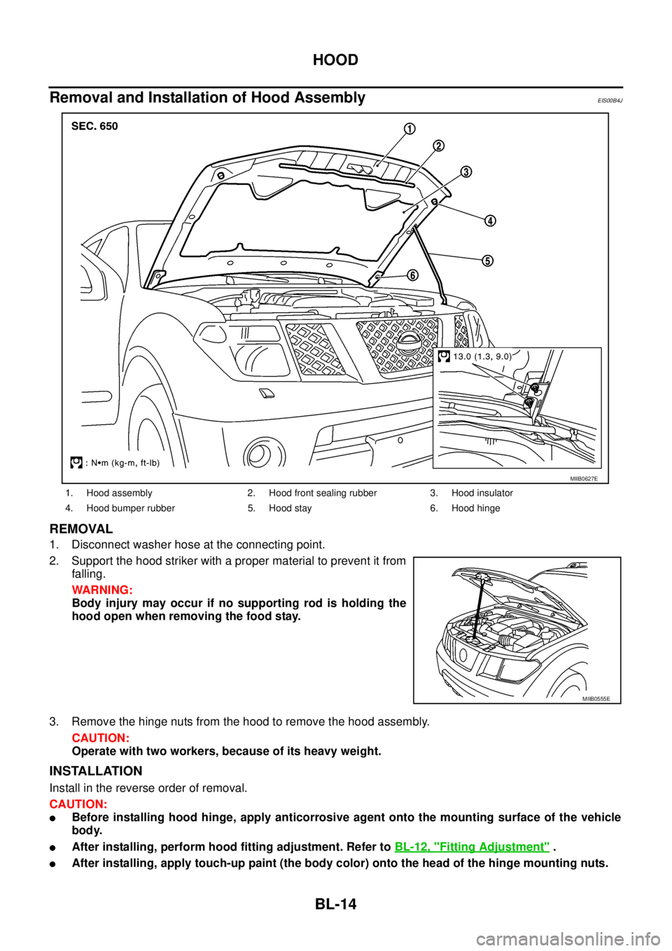
Removal and Installation of Hood Assembly
EIS00B4J
REMOVAL
1. Disconnect washer hose at the connecting point.
2. Support the hood striker with a proper material to prevent it from
falling.
WARNING:
Body injury may occur if no supporting rod is holding the
hood open when removing the food stay.
3. Remove the hinge nuts from the hood to remove the hood assembly.
CAUTION:
Operate with two workers, because of its heavy weight.
INSTALLATION
Install in the reverse order of removal.
CAUTION:
lBefore installing hood hinge, apply anticorrosive agent onto the mounting surface of the vehicle
body.
lAfter installing, perform hood fitting adjustment. Refer toBL-12, "Fitting Adjustment".
lAfter installing, apply touch-up paint (the body color) onto the head of the hinge mounting nuts.
1. Hood assembly 2. Hood front sealing rubber 3. Hood insulator
4. Hood bumper rubber 5. Hood stay 6. Hood hinge
MIIB0627E
MIIB0555E
Page 599 of 3171
HOOD
BL-15
C
D
E
F
G
H
J
K
L
MA
B
BL
Removal and Installation of Hood HingeEIS00C49
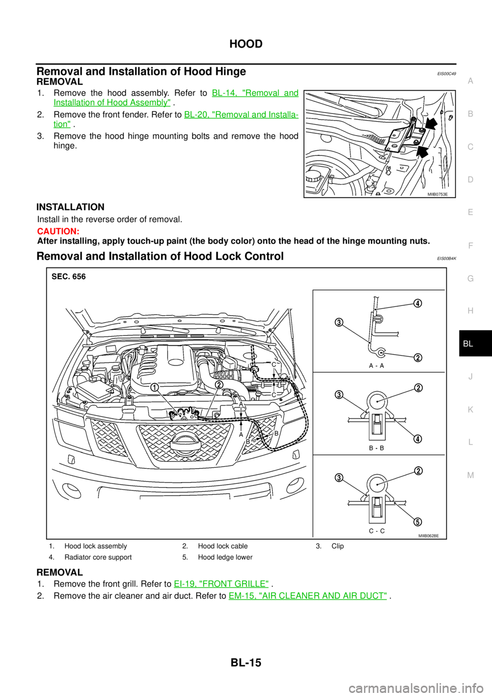
REMOVAL
1. Remove the hood assembly. Refer toBL-14, "Removal and
Installation of Hood Assembly".
2. Remove the front fender. Refer toBL-20, "
Removal and Installa-
tion".
3. Remove the hood hinge mounting bolts and remove the hood
hinge.
INSTALLATION
Install in the reverse order of removal.
CAUTION:
After installing, apply touch-up paint (the body color) onto the head of the hinge mounting nuts.
Removal and Installation of Hood Lock ControlEIS00B4K
REMOVAL
1. Remove the front grill. Refer toEI-19, "FRONT GRILLE".
2. Remove the air cleaner and air duct. Refer toEM-15, "
AIR CLEANER AND AIR DUCT".
MIIB0753E
1. Hood lock assembly 2. Hood lock cable 3. Clip
4. Radiator core support 5. Hood ledge lower
MIIB0628E
Page 604 of 3171
BL-20
FRONT FENDER
FRONT FENDER
PFP:63100
Removal and InstallationEIS00BK0
REMOVAL
1. Remove the front bumper. Refer toEI-15, "FRONT BUMPER".
2. Remove the headlamp. Refer toLT-30, "
Removal and Installation".
3. Remove the front fender protector. Refer toEI-22, "
Removal and Installation of Front Fender Protector".
4. Remove the front side turn signal lamp. Refer toLT- 111 , "
Removal and Installation of Front Turn Signal
Lamp".
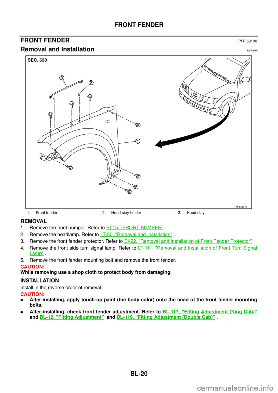
5. Remove the front fender mounting bolt and remove the front fender.
CAUTION:
While removing use a shop cloth to protect body from damaging.
INSTALLATION
Install in the reverse order of removal.
CAUTION:
lAfter installing, apply touch-up paint (the body color) onto the head of the front fender mounting
bolts.
lAfter installing, check front fender adjustment. Refer toBL-117, "Fitting Adjustment (King Cab)"
andBL-12, "Fitting Adjustment"andBL-119, "Fitting Adjustment (Double Cab)".
1. Front fender 2. Hood stay holder 3. Hood stay
MIIB0557E
Page 607 of 3171
POWERDOORLOCKSYSTEM
BL-23
C
D
E
F
G
H
J
K
L
MA
B
BL
System DescriptionEIS00D7R
Power is supplied at all times
lthrough 50A fusible link (letterG, located in the fuse and fusible link box)
lto BCM terminal 57
lthrough 10A fuse [No. 21, located in the fuse block (J/B)]
lto BCM terminal 41
lthrough 10A fuse [No. 22, located in the fuse block (J/B)]
lto key switch terminal 2.
When key switch is ON, power is supplied
lthrough key switch terminal 1
lto BCM terminal 5.
When ignition switch is in ON or START position
lthrough 10A fuse [No. 1, located in the fuse block (J/B)]
lto BCM terminal 3.
Ground is supplied
lto BCM terminal 55
lthrough body grounds M21, M80 and M83.
Door switch operation
When front door switch (driver side) is ON (door is OPEN), ground is supplied
lto BCM terminal 15
lthrough front door switch (driver side) terminal 2
lthrough front door switch (driver side) case ground.
When front door switch (passenger side) is ON (door is OPEN), ground is supplied
lto BCM terminal 14
lthrough front door switch (passenger side) terminal 2
lthrough front door switch (passenger side) case ground.
When rear door switch LH is ON (door is OPEN), ground is supplied (Double cab model)
lto BCM terminal 16
lthrough rear door switch LH terminal 2
lthrough rear door switch LH case ground.
When rear door switch RH is ON (door is OPEN), ground is supplied (Double cab model)
lto BCM terminal 12
lthrough rear door switch RH terminal 2
lthrough rear door switch RH case ground.
Key cylinder switch operation (Without multi-remote control system)
When key cylinder is turned to lock position, ground is supplied
lthrough BCM terminal 34
lto key cylinder switch (driver and passenger side) terminals 4
lthrough key cylinder switch (driver and passenger side) terminals 5
lthrough body ground M21, M80 and M83
then all doors are locked.
When key cylinder is turned to unlock position, ground is supplied
lthrough BCM terminal 32
lto key cylinder switch (driver and passenger side) terminal 6
lthrough key cylinder switch (driver and passenger side) terminal 5
lthrough body ground M21, M80 and M83
then all doors are unlocked.
Power door lock operation with door lock/unlock switch
When doors are lock by door lock/unlock switch, ground is supplied