2005 NISSAN NAVARA body
[x] Cancel search: bodyPage 608 of 3171

BL-24
POWER DOOR LOCK SYSTEM
lto BCM terminal 34
lthrough door lock /unlock switch terminals 1 and 3
lthrough body grounds M21, M80 and M83.
then all doors are locked.
When door lock/unlock switch is locked, ground is supplied
lthrough BCM terminal 56
lthrough all door actuators terminal 3
lthrough all door lock actuators terminal 2
lthrough back door lock actuator terminals 1 and 3
lto BCM terminals 54 and 60.
then all doors actuators are locked
Power door unlock operation with door lock/unlock switch
When doors are unlock by door lock/unlock switch, ground is supplied
lto BCM terminal 32
lthrough door lock/unlock switch terminals 2 and 3
lthrough body grounds M21, M80 and M83.
then all doors are locked.
When door lock/unlock switch is unlocked, ground is supplied
lthrough BCM terminals 54 and 60
lthrough all door lock actuators terminal 2
lthrough all door lock actuators terminal 3
lthen all door actuators are unlock
lto BCM terminal 56.
Door lock/unlock switch indicator operation
When door lock/unlock switch is locked, all doors are locked, door lock/unlock switch indicator is on, and
ground is supplied
lto BCM terminal 17
lthrough door lock/unlock switch terminals 5 and 3
lthrough body grounds M21, M80 and M83.
OUTLINE
Function Available by Operating the Door Lock/Unlock Switch
lOperating the door lock/unlock switch to “LOCK” will lock all doors.
lOperating the door lock/unlock switch to “UNLOCK” will unlock all doors.
NOTE:
Unlock via the interior door handles and door lock/unlock switch is always possible.
Door Lock Warning Function
Under following conditions lock actuators will not respond and buzzer warning will beeps while pressing door
lock/unlock switch in LOCK direction.
lIgnition switch is turned OFF
lMechanical key is out of ignition key cylinder
lDoor is opened (except driver side door)
Key Reminder Function
Under following conditions lock actuators will lock the door once, but then immediately unlock all doors and
buzzer warning will beeps while pressing door lock/unlock switch in LOCK direction.
lIgnition switch is turned OFF
lMechanical key is inserted in ignition key cylinder
lDriver side door is opened
Door Lock/Unlock Switch Indicator
The Door lock/unlock switch indicates door lock status. The indicator will illuminates when a lock operation is
accomplish, during this state, if any door is open, the indicator will turn OFF.
Page 641 of 3171
POWER DOOR LOCK — SUPER LOCK —
BL-57
C
D
E
F
G
H
J
K
L
MA
B
BL
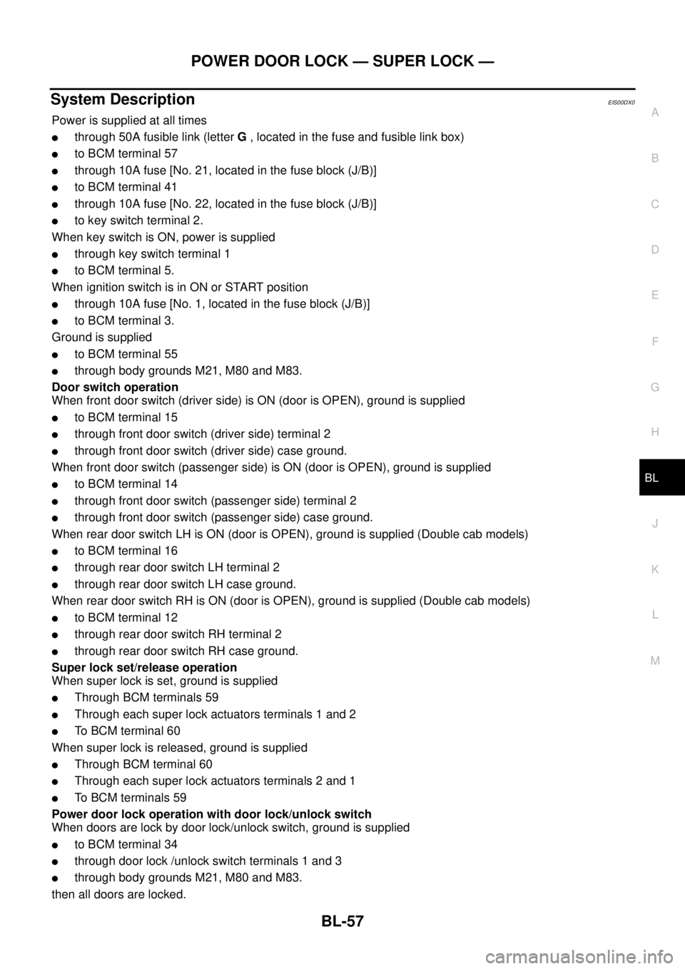
System DescriptionEIS00DX0
Power is supplied at all times
lthrough 50A fusible link (letterG, located in the fuse and fusible link box)
lto BCM terminal 57
lthrough 10A fuse [No. 21, located in the fuse block (J/B)]
lto BCM terminal 41
lthrough 10A fuse [No. 22, located in the fuse block (J/B)]
lto key switch terminal 2.
When key switch is ON, power is supplied
lthrough key switch terminal 1
lto BCM terminal 5.
When ignition switch is in ON or START position
lthrough 10A fuse [No. 1, located in the fuse block (J/B)]
lto BCM terminal 3.
Ground is supplied
lto BCM terminal 55
lthrough body grounds M21, M80 and M83.
Door switch operation
When front door switch (driver side) is ON (door is OPEN), ground is supplied
lto BCM terminal 15
lthrough front door switch (driver side) terminal 2
lthrough front door switch (driver side) case ground.
When front door switch (passenger side) is ON (door is OPEN), ground is supplied
lto BCM terminal 14
lthrough front door switch (passenger side) terminal 2
lthrough front door switch (passenger side) case ground.
When rear door switch LH is ON (door is OPEN), ground is supplied (Double cab models)
lto BCM terminal 16
lthrough rear door switch LH terminal 2
lthrough rear door switch LH case ground.
When rear door switch RH is ON (door is OPEN), ground is supplied (Double cab models)
lto BCM terminal 12
lthrough rear door switch RH terminal 2
lthrough rear door switch RH case ground.
Super lock set/release operation
When super lock is set, ground is supplied
lThrough BCM terminals 59
lThrough each super lock actuators terminals 1 and 2
lTo BCM terminal 60
When super lock is released, ground is supplied
lThrough BCM terminal 60
lThrough each super lock actuators terminals 2 and 1
lTo BCM terminals 59
Power door lock operation with door lock/unlock switch
When doors are lock by door lock/unlock switch, ground is supplied
lto BCM terminal 34
lthrough door lock /unlock switch terminals 1 and 3
lthrough body grounds M21, M80 and M83.
then all doors are locked.
Page 642 of 3171

BL-58
POWER DOOR LOCK — SUPER LOCK —
When door lock/unlock switch is locked, ground is supplied
lthrough BCM terminal 56
lthrough all door actuators terminal 3
lthrough all door lock actuators terminal 2
lthrough back door lock actuator terminals 1 and 3
lto BCM terminals 54 and 60.
then all doors actuators are locked
Power door unlock operation with door lock/unlock switch
When doors are unlock by door lock/unlock switch, ground is supplied
lto BCM terminal 32
lthrough door lock/unlock switch terminals 2 and 3
lthrough body grounds M21, M80 and M83.
then all doors are locked.
When door lock/unlock switch is unlocked, ground is supplied
lthrough BCM terminals 54 and 60
lthrough all door lock actuators terminal 2
lthrough all door lock actuators terminal 3
lthen all door actuators are unlock
lto BCM terminal 56.
Door lock/unlock switch indicator operation
When door lock/unlock switch is locked, all doors are locked, door lock/unlock switch indicator is on, and
ground is supplied
lto BCM terminal 17
lthrough door lock/unlock switch terminals 5 and 3
lthrough body grounds M21, M80 and M83.
OUTLINE
Power door lock systems with super lock function provides a higher anti-theft performance than conventional
power door lock systems. The super lock system is controlled by BCM (Body Control Module).
Pressing LOCK button on key fob once will lock all doors and activate super lock simultaneously.
When super lock is set, all doors cannot be opened from inside.
Pressing UNLOCK button once on key fob will unlock driver side door (unlock all doors if anti-hijack system is
disabled and during this state, super lock is still active). Second press on the UNLOCK button within 5 second
from the first will unlock all doors and release super lock simultaneously.
Functions Available By Operating the Door Lock/Unlock Switch
lOperating the door lock/unlock switch in the control panel will activate all doors actuator to lock or unlock.
If any doors are opened (except the driver side) during operating the door lock/unlock switch in lock direc-
tion, the door lock actuators will not response. Unlock via the interior door handles and door lock/unlock
switch is always possible.
lOperating the door lock/unlock switch to “LOCK” will lock the vehicle even while driver side door is
opened.
OPERATION
Set Super Lock Conditions
lWhen all these following conditions are met, BCM receives lock signal from key fob.
–All doors are closed.
–Key is out of the ignition key cylinder.
Release Super Lock Conditions
lBCM unit receives a valid unlock signal from key fob.
lIgnition switch is turned ON (door lock/unlock switch will remain its state, super lock is released).
NOTE:
Door lock/unlock switch is incapable of overriding super lock.
Page 701 of 3171
DOOR
BL-117
C
D
E
F
G
H
J
K
L
MA
B
BL
DOORPFP:80100
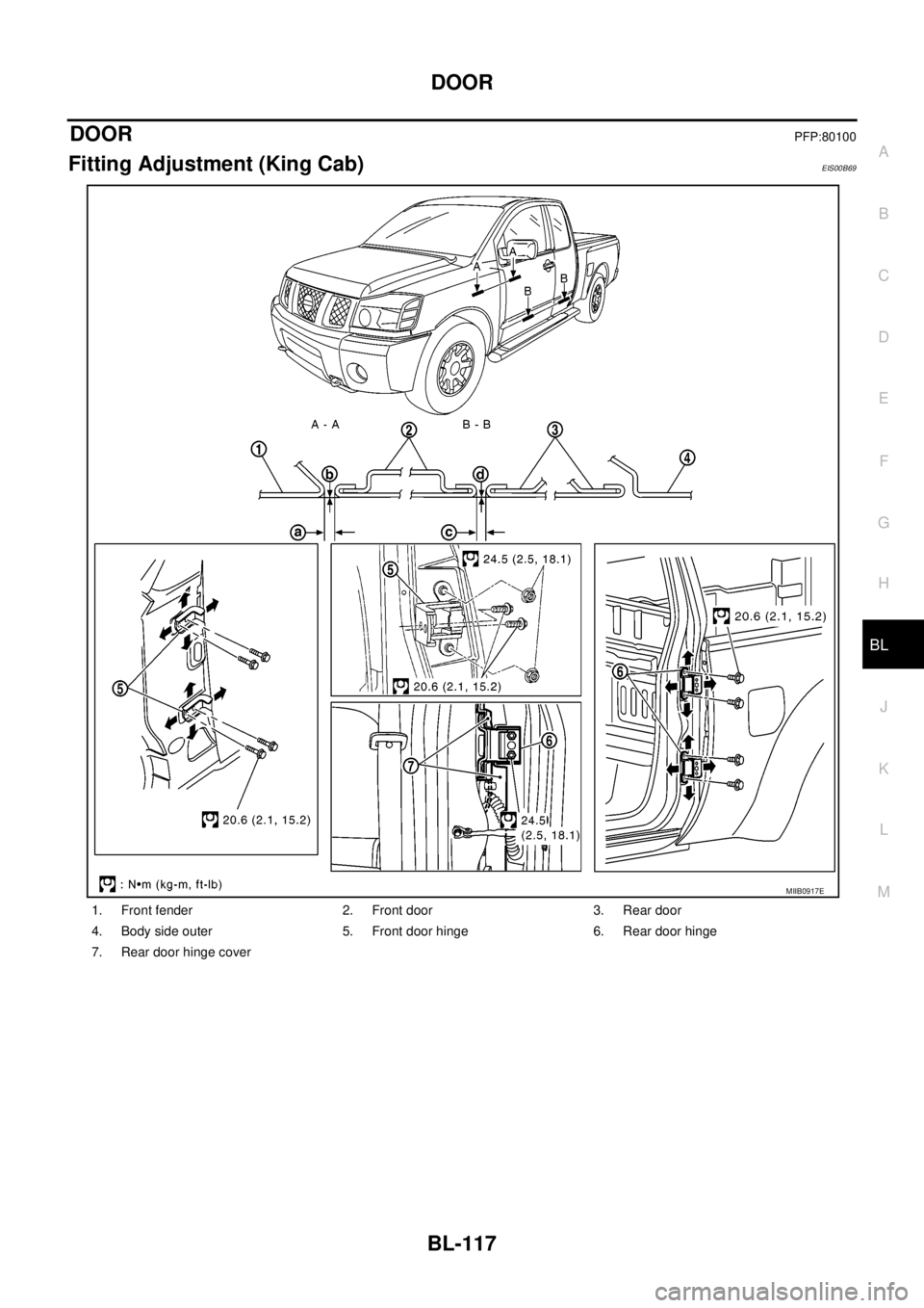
Fitting Adjustment (King Cab)EIS00B69
1. Front fender 2. Front door 3. Rear door
4. Body side outer 5. Front door hinge 6. Rear door hinge
7. Rear door hinge cover
MIIB0917E
Page 702 of 3171
BL-118
DOOR
FRONT DOOR
Longitudinal Clearance and Surface Height Adjustment at Front End
1. Remove the front fender. Refer toBL-20, "Removal and Installation".
2. Loosen the hinge mounting bolts. Raise or lower the front door at rear end to adjust.
REAR DOOR
Longitudinal Clearance and Surface Height Adjustment at Front End
1. Remove the rear door hinge cover mounting clips, and remove the rear door hinge cover.
2. Loosen the rear door hinge mounting bolts.
3. Open the door, and raise or lower the rear end of the door to adjust.
CAUTION:
After installing, apply touch-up paint (the body color) onto the head of the hinge mounting nuts and
mounting bolts.
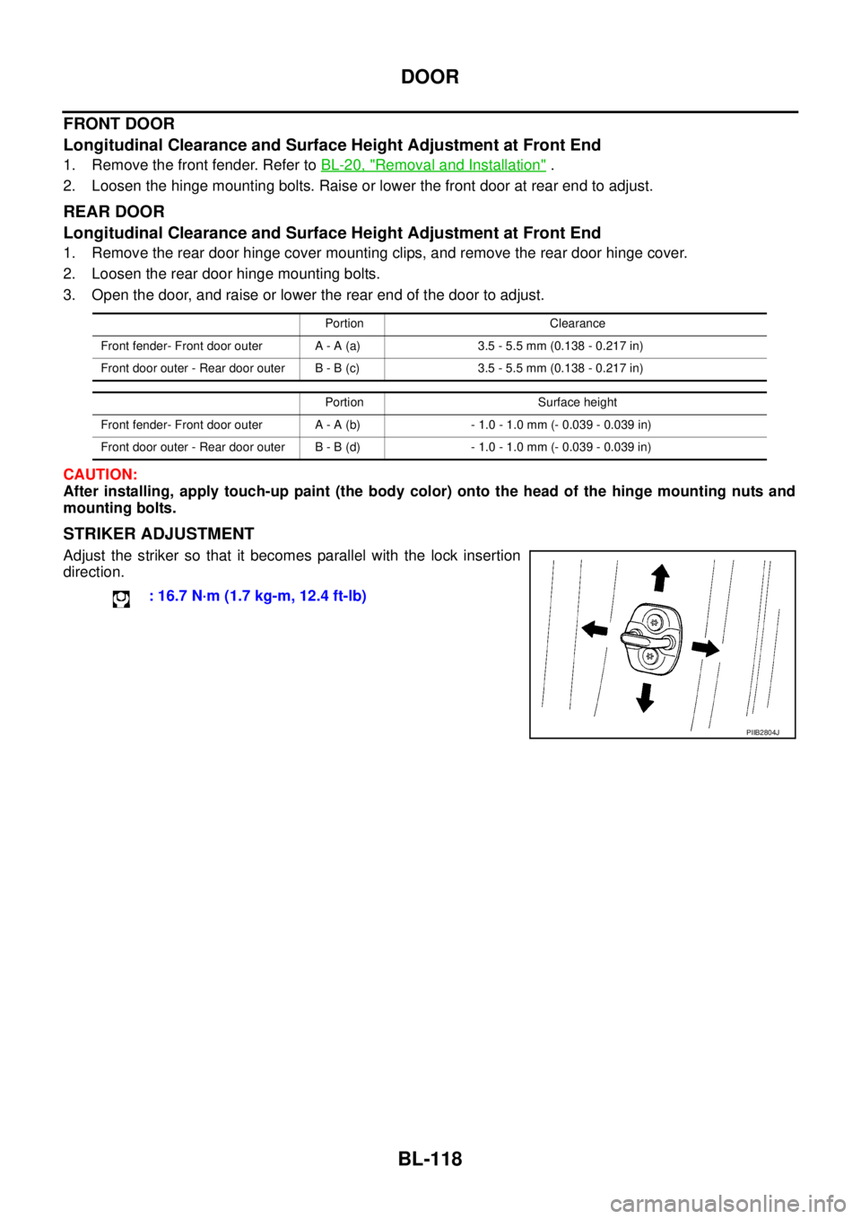
STRIKER ADJUSTMENT
Adjust the striker so that it becomes parallel with the lock insertion
direction.
Portion Clearance
Front fender- Front door outer A - A (a) 3.5 - 5.5 mm (0.138 - 0.217 in)
Front door outer - Rear door outer B - B (c) 3.5 - 5.5 mm (0.138 - 0.217 in)
Portion Surface height
Front fender- Front door outer A - A (b) - 1.0 - 1.0 mm (- 0.039 - 0.039 in)
Front door outer - Rear door outer B - B (d) - 1.0 - 1.0 mm (- 0.039 - 0.039 in)
: 16.7 N·m (1.7 kg-m, 12.4 ft-lb)
PIIB2804J
Page 703 of 3171
DOOR
BL-119
C
D
E
F
G
H
J
K
L
MA
B
BL
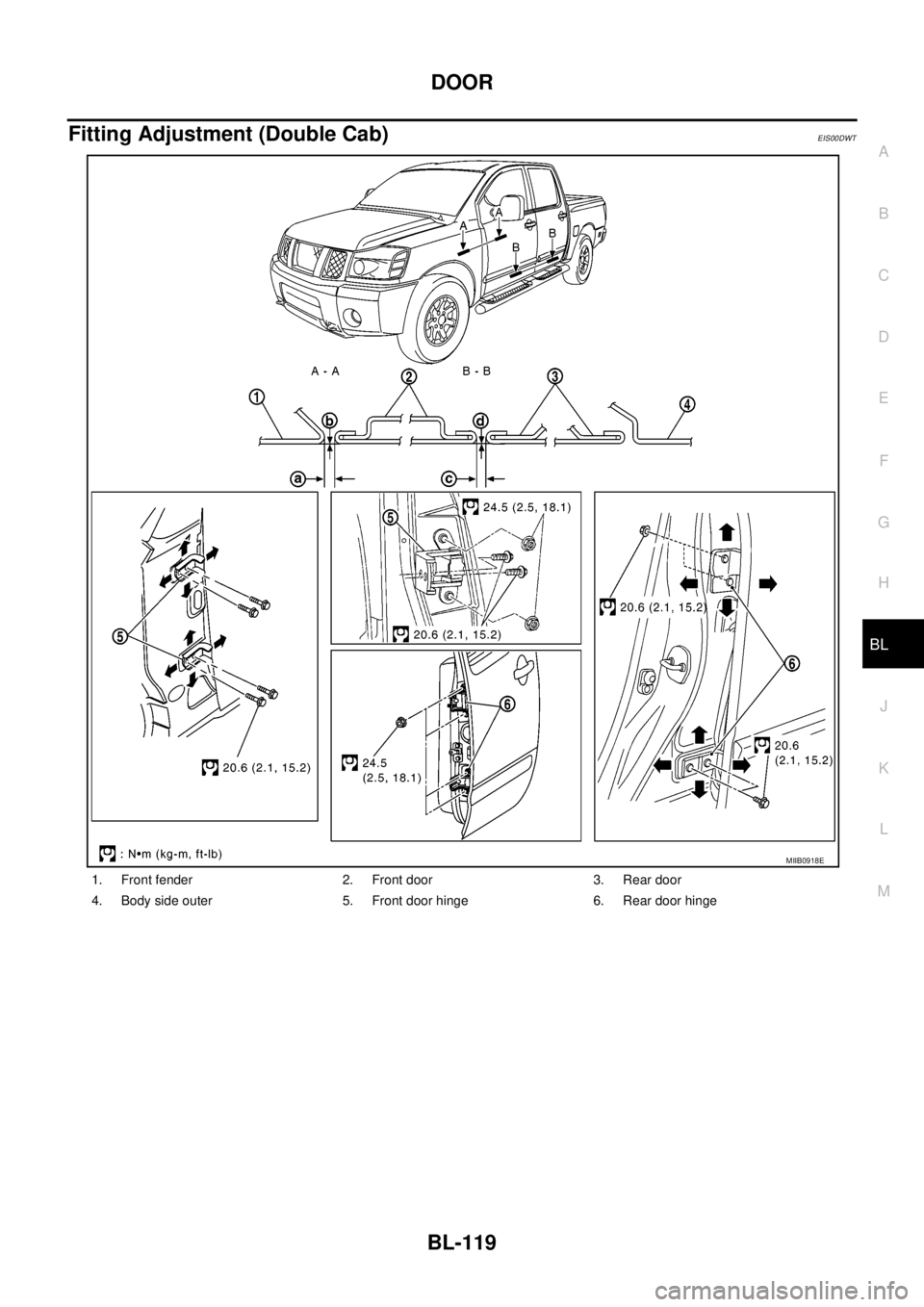
Fitting Adjustment (Double Cab)EIS00DWT
1. Front fender 2. Front door 3. Rear door
4. Body side outer 5. Front door hinge 6. Rear door hinge
MIIB0918E
Page 704 of 3171
BL-120
DOOR
FRONT DOOR
Longitudinal Clearance and Surface Height Adjustment at Front End
1. Remove the front fender. Refer toBL-20, "Removal and Installation".
2. Loosen the hinge mounting bolts. Raise or lower the front door at rear end to adjust.
REAR DOOR
Longitudinal Clearance and Surface Height Adjustment at Front End
1. Remove the center pillar upper finisher. Refer toEI-35, "CENTER PILLAR UPPER FINISHER".
2. Loosen the lower hinge mounting bolts.
3. From inside the vehicle, loosen the upper hinge mounting nuts. Open the door, and raise or lower the rear
end of the door to adjust.
CAUTION:
After installing, apply touch-up paint (the body color) onto the head of the hinge mounting nuts and
mounting bolts.
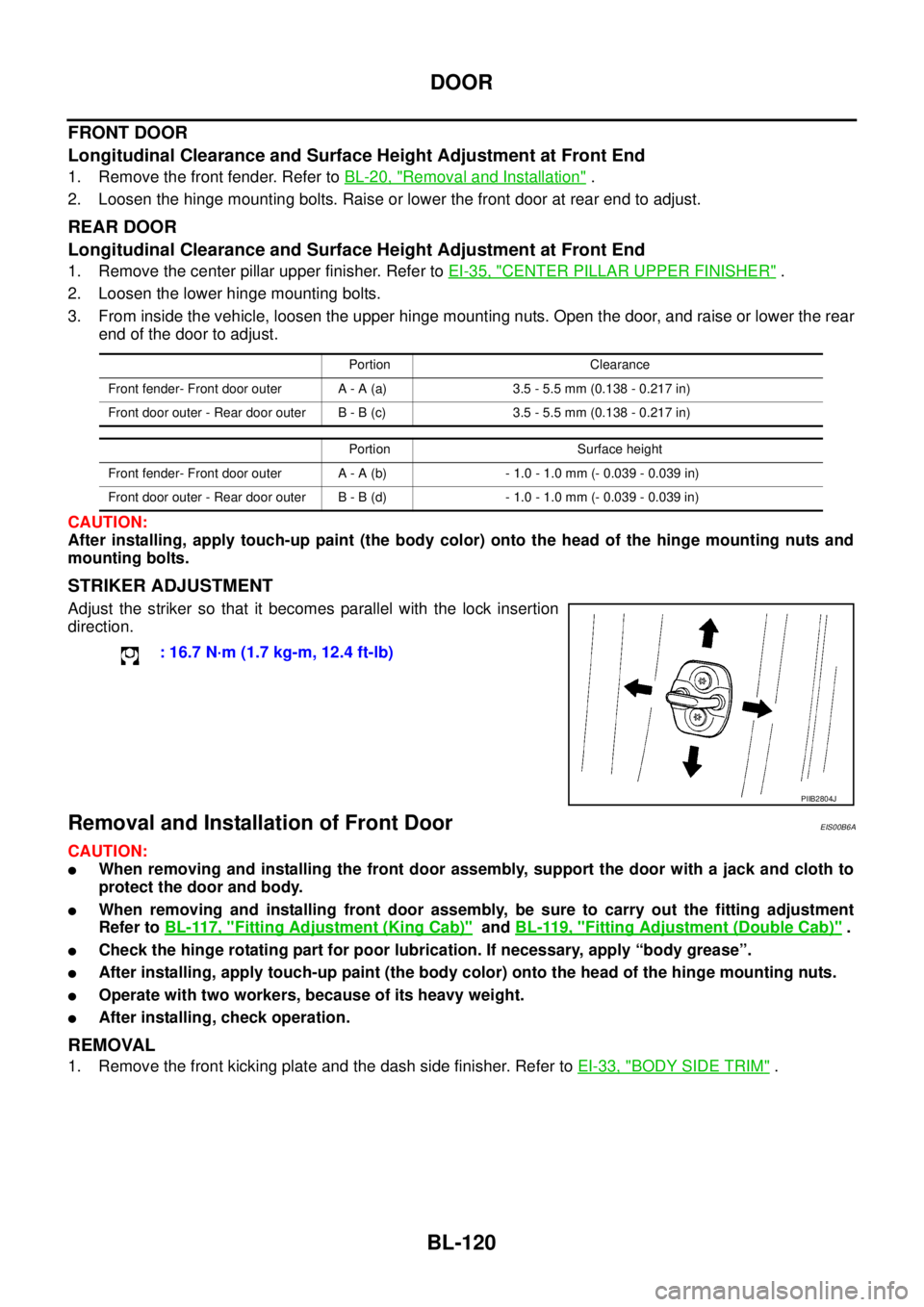
STRIKER ADJUSTMENT
Adjust the striker so that it becomes parallel with the lock insertion
direction.
Removal and Installation of Front DoorEIS00B6A
CAUTION:
lWhen removing and installing the front door assembly, support the door with a jack and cloth to
protect the door and body.
lWhen removing and installing front door assembly, be sure to carry out the fitting adjustment
Refer toBL-117, "
Fitting Adjustment (King Cab)"andBL-119, "Fitting Adjustment (Double Cab)".
lCheck the hinge rotating part for poor lubrication. If necessary, apply “body grease”.
lAfter installing, apply touch-up paint (the body color) onto the head of the hinge mounting nuts.
lOperate with two workers, because of its heavy weight.
lAfter installing, check operation.
REMOVAL
1. Remove the front kicking plate and the dash side finisher. Refer toEI-33, "BODY SIDE TRIM".
Portion Clearance
Front fender- Front door outer A - A (a) 3.5 - 5.5 mm (0.138 - 0.217 in)
Front door outer - Rear door outer B - B (c) 3.5 - 5.5 mm (0.138 - 0.217 in)
Portion Surface height
Front fender- Front door outer A - A (b) - 1.0 - 1.0 mm (- 0.039 - 0.039 in)
Front door outer - Rear door outer B - B (d) - 1.0 - 1.0 mm (- 0.039 - 0.039 in)
: 16.7 N·m (1.7 kg-m, 12.4 ft-lb)
PIIB2804J
Page 705 of 3171
DOOR
BL-121
C
D
E
F
G
H
J
K
L
MA
B
BL
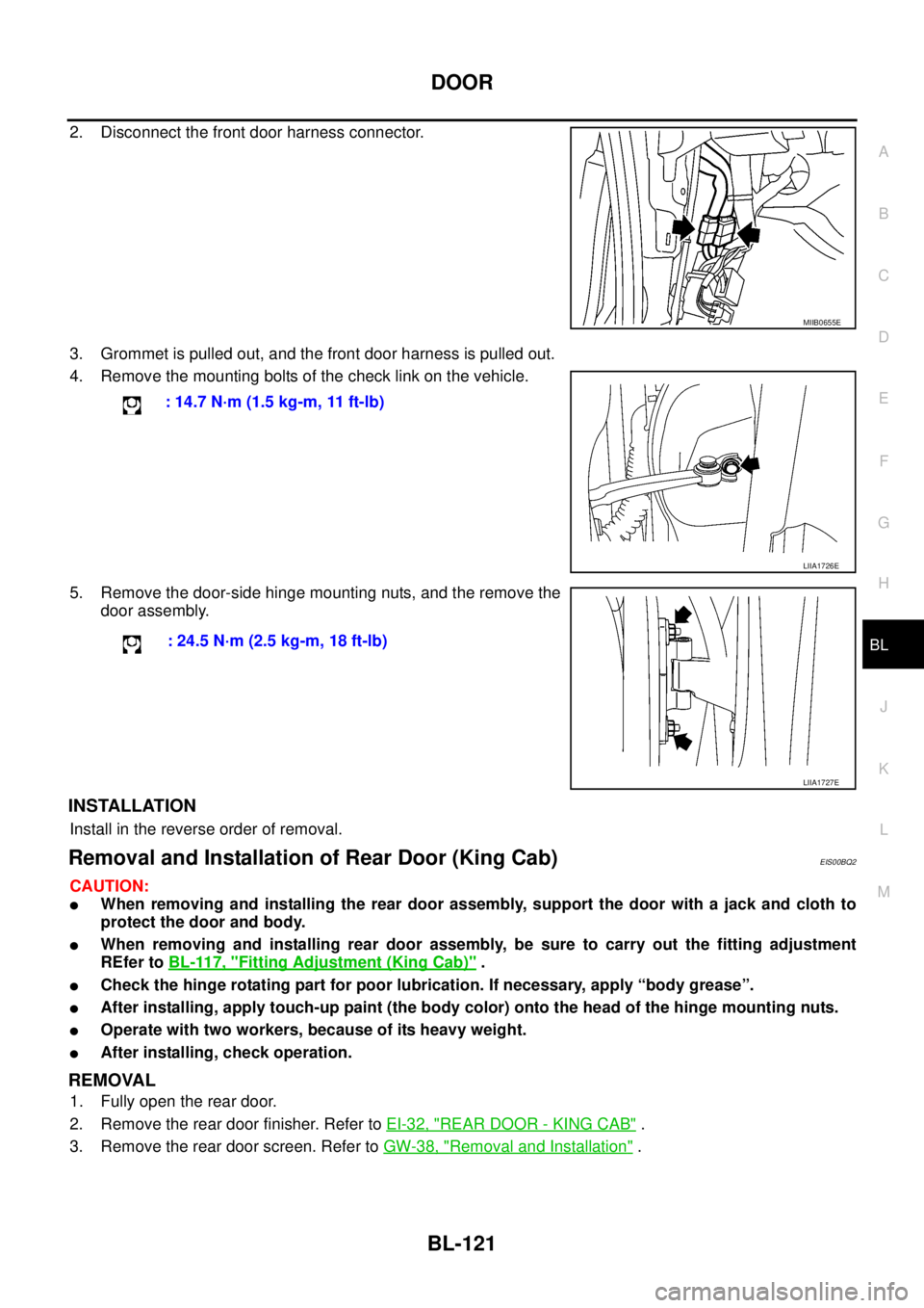
2. Disconnect the front door harness connector.
3. Grommet is pulled out, and the front door harness is pulled out.
4. Remove the mounting bolts of the check link on the vehicle.
5. Remove the door-side hinge mounting nuts, and the remove the
door assembly.
INSTALLATION
Install in the reverse order of removal.
Removal and Installation of Rear Door (King Cab)EIS00BQ2
CAUTION:
lWhen removing and installing the rear door assembly, support the door with a jack and cloth to
protect the door and body.
lWhen removing and installing rear door assembly, be sure to carry out the fitting adjustment
REfer toBL-117, "
Fitting Adjustment (King Cab)".
lCheck the hinge rotating part for poor lubrication. If necessary, apply “body grease”.
lAfter installing, apply touch-up paint (the body color) onto the head of the hinge mounting nuts.
lOperate with two workers, because of its heavy weight.
lAfter installing, check operation.
REMOVAL
1. Fully open the rear door.
2. Remove the rear door finisher. Refer toEI-32, "
REAR DOOR - KING CAB".
3. Remove the rear door screen. Refer toGW-38, "
Removal and Installation".
MIIB0655E
: 14.7 N·m (1.5 kg-m, 11 ft-lb)
LIIA1726E
: 24.5 N·m (2.5 kg-m, 18 ft-lb)
LIIA1727E