2005 NISSAN NAVARA lock
[x] Cancel search: lockPage 2492 of 3171

HEATER & COOLING UNIT ASSEMBLY
MTC-105
C
D
E
F
G
H
I
K
L
MA
B
MTC
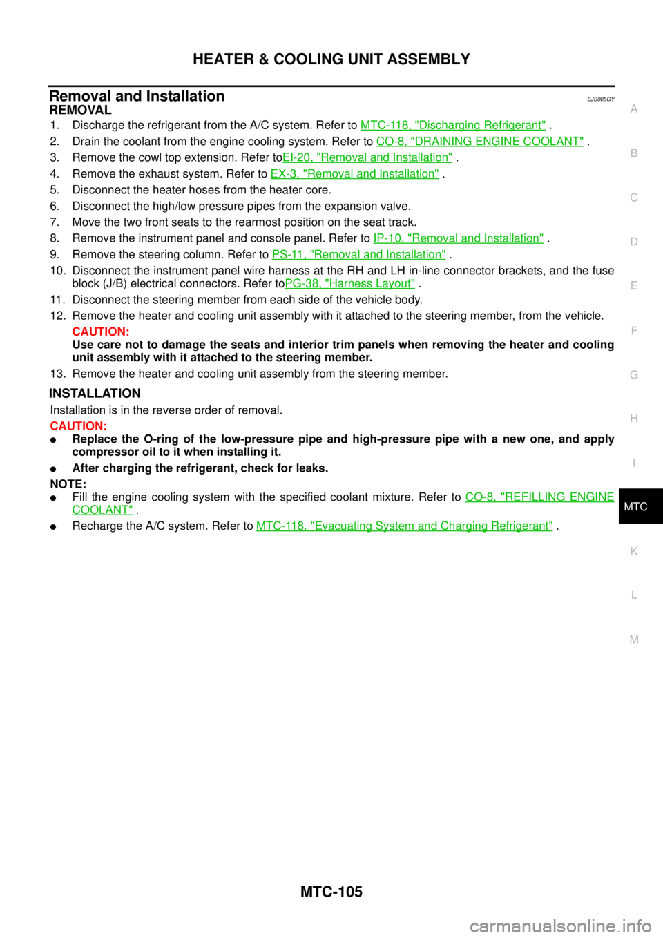
Removal and InstallationEJS005GY
REMOVAL
1. Discharge the refrigerant from the A/C system. Refer toMTC-118, "Discharging Refrigerant".
2. Drain the coolant from the engine cooling system. Refer toCO-8, "
DRAINING ENGINE COOLANT".
3. Remove the cowl top extension. Refer toEI-20, "
Removal and Installation".
4. Remove the exhaust system. Refer toEX-3, "
Removal and Installation".
5. Disconnect the heater hoses from the heater core.
6. Disconnect the high/low pressure pipes from the expansion valve.
7. Move the two front seats to the rearmost position on the seat track.
8. Remove the instrument panel and console panel. Refer toIP-10, "
Removal and Installation".
9. Remove the steering column. Refer toPS-11, "
Removal and Installation".
10. Disconnect the instrument panel wire harness at the RH and LH in-line connector brackets, and the fuse
block (J/B) electrical connectors. Refer toPG-38, "
Harness Layout".
11. Disconnect the steering member from each side of the vehicle body.
12. Remove the heater and cooling unit assembly with it attached to the steering member, from the vehicle.
CAUTION:
Use care not to damage the seats and interior trim panels when removing the heater and cooling
unit assembly with it attached to the steering member.
13. Remove the heater and cooling unit assembly from the steering member.
INSTALLATION
Installation is in the reverse order of removal.
CAUTION:
lReplace the O-ring of the low-pressure pipe and high-pressure pipe with a new one, and apply
compressor oil to it when installing it.
lAfter charging the refrigerant, check for leaks.
NOTE:
lFill the engine cooling system with the specified coolant mixture. Refer toCO-8, "REFILLING ENGINE
COOLANT".
lRecharge the A/C system. Refer toMTC-118, "Evacuating System and Charging Refrigerant".
Page 2504 of 3171

DUCTS AND GRILLES
MTC-117
C
D
E
F
G
H
I
K
L
MA
B
MTC
NOTE:
To remove the overhead console front and rear grilles, turn the grille counter-clockwise to release the
grille from the overhead console trim panel.
Installation
Installation is in the reverse order of removal.
Page 2509 of 3171

MTC-122
REFRIGERANT LINES
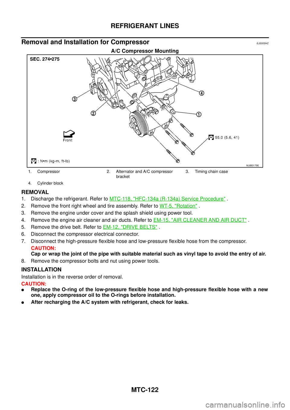
Removal and Installation for Compressor
EJS005HC
A/C Compressor Mounting
REMOVAL
1. Discharge the refrigerant. Refer toMTC-118, "HFC-134a (R-134a) Service Procedure".
2. Remove the front right wheel and tire assembly. Refer toWT-5, "
Rotation".
3. Remove the engine under cover and the splash shield using power tool.
4. Remove the engine air cleaner and air ducts. Refer toEM-15, "
AIR CLEANER AND AIR DUCT".
5. Remove the drive belt. Refer toEM-12, "
DRIVE BELTS".
6. Disconnect the compressor electrical connector.
7. Disconnect the high-pressure flexible hose and low-pressure flexible hose from the compressor.
CAUTION:
Cap or wrap the joint of the pipe with suitable material such as vinyl tape to avoid the entry of air.
8. Remove the compressor bolts and nut using power tools.
INSTALLATION
Installation is in the reverse order of removal.
CAUTION:
lReplace the O-ring of the low-pressure flexible hose and high-pressure flexible hose with a new
one, apply compressor oil to the O-rings before installation.
lAfter recharging the A/C system with refrigerant, check for leaks.
MJIB0179E
1. Compressor 2. Alternator and A/C compressor
bracket3. Timing chain case
4. Cylinder block
Page 2522 of 3171

SERVICE DATA AND SPECIFICATIONS (SDS)
MTC-135
C
D
E
F
G
H
I
K
L
MA
B
MTC
SERVICE DATA AND SPECIFICATIONS (SDS)PFP:00030
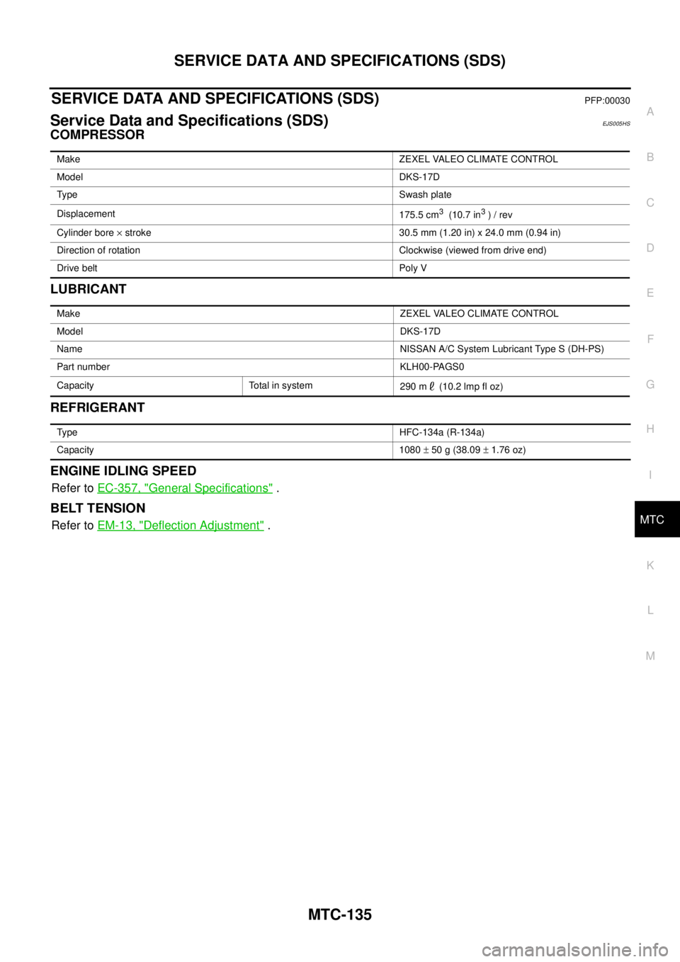
Service Data and Specifications (SDS)EJS005HS
COMPRESSOR
LUBRICANT
REFRIGERANT
ENGINE IDLING SPEED
Refer toEC-357, "General Specifications".
BELT TENSION
Refer toEM-13, "Deflection Adjustment".
MakeZEXEL VALEO CLIMATE CONTROL
ModelDKS-17D
Ty p eSwash plate
Displacement
175.5 cm
3(10.7 in3)/rev
Cylinder bore´stroke 30.5 mm (1.20 in) x 24.0 mm (0.94 in)
Direction of rotation Clockwise (viewed from drive end)
Drive belt Poly V
MakeZEXEL VALEO CLIMATE CONTROL
ModelDKS-17D
NameNISSAN A/C System Lubricant Type S (DH-PS)
Part number KLH00-PAGS0
Capacity Total in system
290m (10.2lmpfloz)
Ty p eHFC-134a (R-134a)
Capacity 1080±50g(38.09±1.76 oz)
Page 2531 of 3171

PG-2
REAR DOOR LH HARNESS/KING CAB MOD-
ELS ...................................................................... 66
REAR DOOR RH HARNESS/KING CAB MOD-
ELS ...................................................................... 66
TAIL HARNESS ................................................... 67
Wiring Diagram Codes (Cell Codes) ....................... 68
ELECTRICAL UNITS LOCATION ............................. 71
Electrical Units Location ......................................... 71
ENGINE COMPARTMENT .................................. 71
PASSENGER COMPARTMENT .......................... 72
Fuse ........................................................................ 74
Fusible Link ............................................................ 74
Circuit Breaker (Built Into BCM) ............................. 74
HARNESS CONNECTOR ......................................... 75
Description .............................................................. 75
HARNESS CONNECTOR (TAB-LOCKING
TYPE) .................................................................. 75
HARNESS CONNECTOR (SLIDE-LOCKINGTYPE) .................................................................. 76
HARNESS CONNECTOR (DIRECT-CONNECT
SRS COMPONENT TYPE) .................................. 77
ELECTRICAL UNITS ................................................ 78
Terminal Arrangement ............................................. 78
STANDARDIZED RELAY .......................................... 79
Description .............................................................. 79
NORMAL OPEN, NORMAL CLOSED AND
MIXED TYPE RELAYS ........................................ 79
TYPE OF STANDARDIZED RELAYS .................. 79
SUPER MULTIPLE JUNCTION (SMJ) ...................... 81
Terminal Arrangement ............................................. 81
FUSE BLOCK - JUNCTION BOX (J/B) .................... 83
Terminal Arrangement ............................................. 83
FUSE AND FUSIBLE LINK BOX .............................. 84
Terminal Arrangement ............................................. 84
FUSE AND RELAY BOX ........................................... 85
Terminal Arrangement ............................................. 85
Page 2543 of 3171

PG-14
IPDM E/R (INTELLIGENT POWER DISTRIBUTION MODULE ENGINE ROOM)
IPDM E/R (INTELLIGENT POWER DISTRIBUTION MODULE ENGINE ROOM)
PFP:284B7
System DescriptionEKS00PA8
lIPDM E/R (Intelligent Power Distribution Module Engine Room) integrates the relay box and fuse block
which were originally placed in engine compartment. It controls integrated relays via IPDM E/R control cir-
cuits.
lIPDM E/R-integrated control circuits perform ON-OFF operation of relays, CAN communication control,
etc.
lIt controls operation of each electrical component via ECM, BCM and CAN communication lines.
CAUTION:
None of the IPDM E/R integrated relays can be removed.
SYSTEMS CONTROLLED BY IPDM E/R
IPDM E/R receives a request signal from each Control unit with CAN communication. It controls each system.
CAN COMMUNICATION LINE CONTROL
With CAN communication, by connecting each control unit using two communication lines (CAN L-line, CAN
H-line), it is possible to transmit a maximum amount of information with minimum wiring. Each control unit can
transmit and receive data, and reads necessary information only.
1. Fail-safe control
lWhen CAN communication with other control units is impossible, IPDM E/R performs fail-safe control.
After CAN communication returns to normal operation, it also returns to normal control.
lOperation of control parts by IPDM E/R during fail-safe mode is as follows:
Control system Transmit control unit Control part
Lamp control BCM
lHead lamps (HI, LO)
lTail lamps, parking and license plate lamps
lFront fog lamps
Wiper control BCM Front wipers
Rear window defogger control BCM Rear window defogger
A/C compressor control ECM A/C compressor
Starter control TCM Starter motor
Cooling fan control ECM Cooling fan
Controlled system Fail-safe mode
Headlamps
lWith the ignition switch ON, the headlamp low is ON.
lWith the ignition switch OFF, the headlamp low is OFF.
Tail, parking and license plate lamps
lWith the ignition switch ON, the tail lamp is ON.
lWith the ignition switch OFF, the tail lamp is OFF.
Cooling fan
lWith the ignition switch ON, the cooling fan HI operates.
lWith the ignition switch OFF, the cooling fan stops.
Front wipersUntil the ignition switch is turned off, the front wiper LO and HI remains in the same status it
was in just before fail-safe control was initiated.
Rear window defogger Rear window defogger OFF
A/C compressor A/C compressor OFF
Front fog lamps Front fog lamp OFF
Page 2547 of 3171

PG-18
IPDM E/R (INTELLIGENT POWER DISTRIBUTION MODULE ENGINE ROOM)
5. Touch “RECORD” while monitoring to record the status of the item being monitored. To stop recording,
touch “STOP”.
All Signals, Main Signals, Selection From Menu
NOTE:
Perform monitoring of IPDM E/R data with the ignition switch ON. When the ignition switch is in ACC position,
display may not be correct.
CAN DIAG SUPPORT MNTR
Refer toLAN-15, "CAN Diagnostic Support Monitor".
ACTIVE TEST
Operation Procedure
1. Touch “ACTIVE TEST” on “SELECT DIAG-MODE” screen.
2. Touch item to be tested, and check operation.
3. Touch “START”.
4. Touch “STOP” while testing to stop the operation.
Item nameCONSULT-II
screen displayDisplay or unitMonitor item selection
Description
ALL
SIGNALSMAIN
SIGNALSSELECTION
FROM MENU
Motor fan requestMOTOR FAN
REQ1/2/3/4 X X X Signal status input from ECM
A/C compressor
requestAC COMP REQ ON/OFF X X X Signal status input from ECM
Tail & clear
requestTAIL & CLR REQ ON/OFF X X X Signal status input from BCM
Headlamp LO
requestHL LO REQ ON/OFF X X X Signal status input from BCM
Headlamp HI
requestHL HI REQ ON/OFF X X X Signal status input from BCM
Front fog lamp
requestFR FOG REQ ON/OFF X X X Signal status input from BCM
Headlamp washer
requestHL WASHER
REQON/OFF X X Signal from input from BCM
Front wiper
requestFR WIP REQSTOP/1LOW/
LOW/HIX X X Signal status input from BCM
Wiper auto stopWIP AUTO
STOPACT P/STOP P X X X Output status of IPDM E/R
Wiper protection WIP PROT OFF/BLOCK X X X Control status of IPDM E/R
Starter request ST RLY REQ ON/OFF X X
Status of input signal
NOTE
Ignition relay
statusIGN RLY ON/OFF X X XIgnition relay status monitored
with IPDM E/R
Rear defogger
requestRR DEF REQ ON/OFF X X X Signal status input from BCM
Oil pressure
switchOIL P SW OPEN/CLOSE X XSignal status input from IPDM
E/R
Hood switch HOOD SW OFF XSignal status input from IPDM
E/R (function is not enabled)
Theft warning
horn requestTHFT HRN REQ ON/OFF X X Signal status input from BCM
Horn chirp HORN CHIRP ON/OFF X X Output status of IPDM E/R
Page 2597 of 3171

PG-68
HARNESS
Wiring Diagram Codes (Cell Codes)
EKS00LJ9
Use the chart below to find out what each wiring diagram code stands for.
Refer to the wiring diagram code in the alphabetical index to find the location (page number) of each wiring
diagram.
Code Section Wiring Diagram Name
A/C,A ATC Auto Air Conditioner
A/C,M MTC Manual Air Conditioner
ABS BRC Anti-lock Brake System
APP1PW EC Accelerator Pedal Position Sensor 1 Power
APP2PW EC Accelerator Pedal Position Sensor 2 Power
APPS1 EC Accelerator Pedal Position Sensor 1
APPS2 EC Accelerator Pedal Position Sensor 2
APPS3 EC Accelerator Pedal Position Sensor
ASC/BS EC ASCD Brake Switch
ASC/SW EC ASCD Steering Switch
ASCBOF EC ASCD Brake Switch
ASCIND EC ASCD Indicator
AT/IND DI A/T Indicator Lamp
AUDIO AV Audio
AUTO/L LT Auto Lignt System
BACK/L LT Back-up Lamp
BOOST EC Turbocharger Boost Sensor
CAN AT CAN Communication Line
CAN EC CAN Communication Line
CAN LAN CAN System
CHARGE SC Charging System
CHIME DI Warning Chime
CIGER WW Cigarette Lighter
CKPS EC Crankshaft Position Sensor
CMPS EC Camshaft Position Sensor
COMBSW LT Combination Switch
COMM AV Audio Visual Communication Line
COMPAS DI Compass
COOL/F EC Cooling Fan Control
D/LOCK BL Power Door Lock
DIFLOC RFD Rear Final Drive
DEF GW Rear Window Defogger
DTRL LT Headlamp — With Daytime Running Light System
ECMRLY EC ECM Relay
ECTS EC Engine Coolant Temperature Sensor
EGRVLV EC EGR Volume Control System
EMNT EC Electronic Controlled Engine Mount Control Solenoid Valve
F/FOG LT Front Fog Lamp
F/PUMP EC Fuel Pump
FRPS EC Fuel Rail Pressure Sensor
FTS AT A/T Fluid Temperature Sensor