Page 2598 of 3171

HARNESS
PG-69
C
D
E
F
G
H
I
J
L
MA
B
PG
FTS EC Fuel Pump Temperature Sensor
GLOW EC Glow Control System
H/AIM LT Headlamp Aiming Control System
H/LAMP LT Headlamp
HEATUP EC Heat Up Switch
HLC WW Headlamp Washer
HORN WW Horn
HSEAT SE Heated Seat
I/KEY BL Intelligent Key System
I/MIRR GW Inside Mirror (Auto Anti-dazzling Mirror)
IATS EC Intake Air Temperature Sensor
ILL LT Illumination
INJ/PW EC Fuel Injector Power Supply
INJECT EC Fuel Injector
INT/L LT Room and Map Lamps
INT/V EC Intake Air Control Valve Control Solenoid Valve
MAFS EC Mass Air Flow Sensor
MAIN AT Main Power Supply and Ground Circuit
MAIN EC Main Power Supply and Ground Circuit
METER DI Speedometer, Tachometer, Temp. and Fuel Gauges
MIL/DL EC Malfunction Indicator Lamp, Data Link Connector
MIRROR GW Door Mirror
MMSW AT Manual Mode Switch
MULTI BL Multi-remote Control System
NATS BL NATS (Nissan Anti-Theft System)
NAVI AV Navigation System
NONDTC AT NON-detective Items
P/SCKT WW Power Socket
PHONE AV Telephone
PNP/SW AT Park/Neutral Position Switch
PNP/SW EC Park/Neutral Position Switch
POWER PG Power Supply Routing
R/FOG LT Rear Fog Lamp
RP/SEN EC Refrigerant Pressure Sensor
S/LOCK BL Power Door Lock — Super Lock
S/SIG EC Start Signal
SEAT SE Power Seat
SHIFT AT A/T Shift Lock System
SROOF RF Sunroof
SRS SRS Supplemental Restraint System
START SC Starting System
STOP/L LT Stop Lamp
STSIG AT Start Signal Circuit
T/F TF TransferCode Section Wiring Diagram Name
Page 2603 of 3171

PG-74
ELECTRICAL UNITS LOCATION
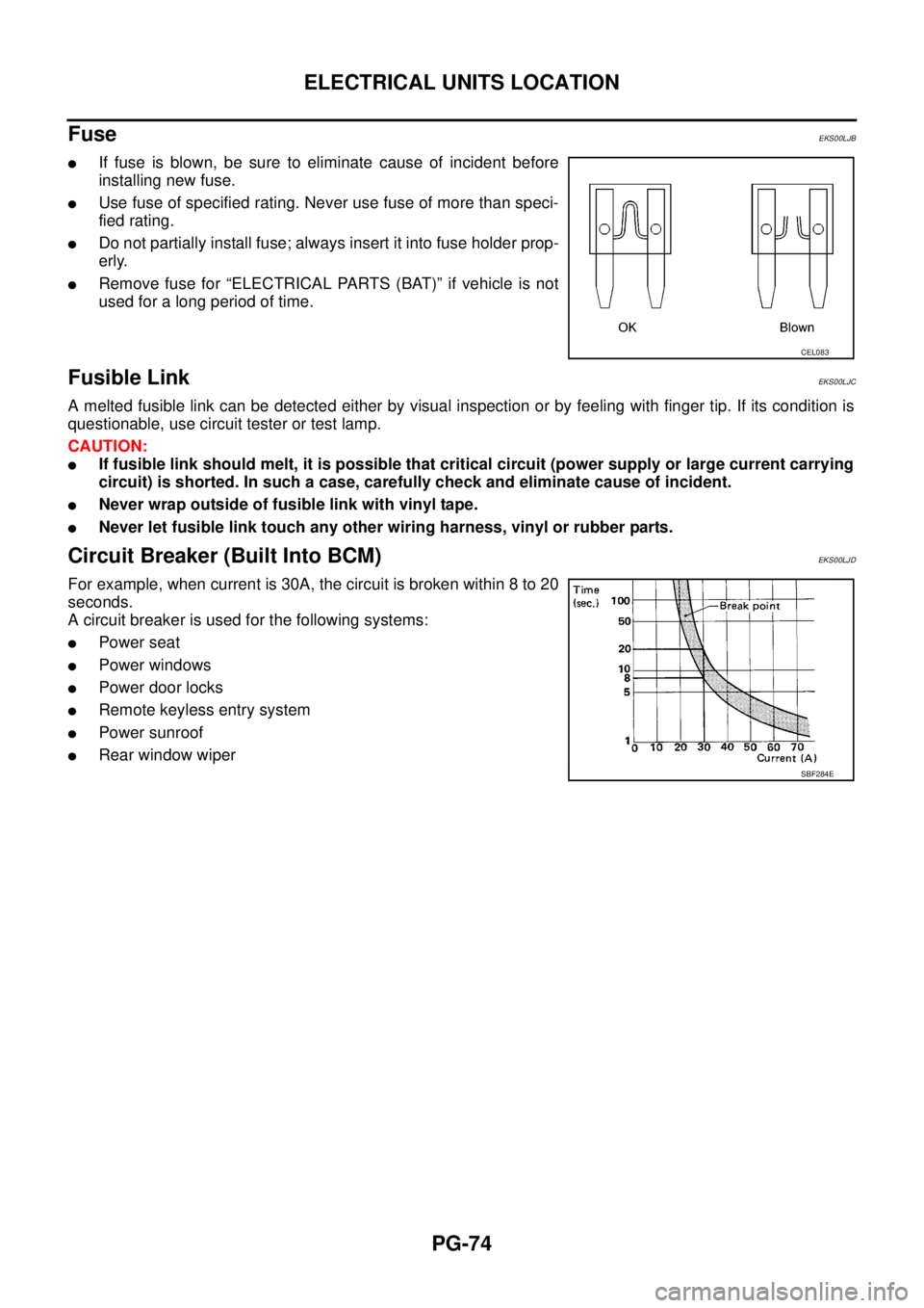
Fuse
EKS00LJB
lIf fuse is blown, be sure to eliminate cause of incident before
installing new fuse.
lUse fuse of specified rating. Never use fuse of more than speci-
fied rating.
lDo not partially install fuse; always insert it into fuse holder prop-
erly.
lRemove fuse for “ELECTRICAL PARTS (BAT)” if vehicle is not
used for a long period of time.
Fusible LinkEKS00LJC
A melted fusible link can be detected either by visual inspection or by feeling with finger tip. If its condition is
questionable, use circuit tester or test lamp.
CAUTION:
lIf fusible link should melt, it is possible that critical circuit (power supply or large current carrying
circuit) is shorted. In such a case, carefully check and eliminate cause of incident.
lNever wrap outside of fusible link with vinyl tape.
lNever let fusible link touch any other wiring harness, vinyl or rubber parts.
Circuit Breaker (Built Into BCM)EKS00LJD
For example, when current is 30A, the circuit is broken within 8 to 20
seconds.
A circuit breaker is used for the following systems:
lPower seat
lPower windows
lPowerdoorlocks
lRemote keyless entry system
lPower sunroof
lRear window wiper
CEL083
SBF284E
Page 2604 of 3171
HARNESS CONNECTOR
PG-75
C
D
E
F
G
H
I
J
L
MA
B
PG
HARNESS CONNECTORPFP:B4341
DescriptionEKS00LJE
HARNESS CONNECTOR (TAB-LOCKING TYPE)
lThe tab-locking type connectors help prevent accidental looseness or disconnection.
lThe tab-locking type connectors are disconnected by pushing or lifting the locking tab(s). Refer to the
illustration below.
Refer to the next page for description of the slide-locking type connector.
CAUTION:
Do not pull the harness or wires when disconnecting the connector.
[Example]
SEL769DA
Page 2605 of 3171
PG-76
HARNESS CONNECTOR
HARNESS CONNECTOR (SLIDE-LOCKING TYPE)
lA new style slide-locking type connector is used on certain systems and components, especially those
related to OBD.
lThe slide-locking type connectors help prevent incomplete locking and accidental looseness or discon-
nection.
lThe slide-locking type connectors are disconnected by pushing or pulling the slider. Refer to the illustra-
tion below.
CAUTION:
lDo not pull the harness or wires when disconnecting the connector.
lBe careful not to damage the connector support bracket when disconnecting the connector.
[Example]
AEL299C
Page 2606 of 3171
HARNESS CONNECTOR
PG-77
C
D
E
F
G
H
I
J
L
MA
B
PG
HARNESS CONNECTOR (DIRECT-CONNECT SRS COMPONENT TYPE)
lSRS direct-connect type harness connectors are used on certain SRS components such as air bag mod-
ules and seat belt pre-tensioners.
lAlways pull up to release black locking tab prior to removing connector from SRS component.
lAlways push down to lock black locking tab after installing connector to SRS component. When locked,
the black locking tab is level with the connector housing.
CAUTION:
lDo not pull the harness or wires when removing connectors
from SRS components.
WHIA0103E
Page 2612 of 3171
FUSE BLOCK - JUNCTION BOX (J/B)
PG-83
C
D
E
F
G
H
I
J
L
MA
B
PG
FUSE BLOCK - JUNCTION BOX (J/B)PFP:24350
Terminal ArrangementEKS00LJI
MKWA3881E
Page 2632 of 3171

NOISE, VIBRATION, AND HARSHNESS (NVH) TROUBLESHOOTING
PS-5
C
D
E
F
H
I
J
K
L
MA
B
PS
NOISE, VIBRATION, AND HARSHNESS (NVH) TROUBLESHOOTINGPFP:00003
NVH Troubleshooting ChartEGS001LC
Use chart below to help you find the cause of the symptom. If necessary, repair or replace these parts.
´: ApplicableReference page
PS-6PS-6PS-18PS-18PS-18PS-6PS-8PS-8EM-12PS-8—
PS-18PS-12PS-11PS-16
NVHinPRsection
NVH in RFD section
NVH in FAX, RAX, FSU, RSU section
NVH in WT section
NVH in WT section
NVHinBRsection
NVHinBRsection
Possible cause and SUSPECTED PARTS
Fluid level
Air in hydraulic system
Outer socket ball joint swinging force
Outer socket ball joint rotating torque
Outer socket ball joint end play
Steering fluid leakage
Steering wheel play
Steering gear rack sliding force
Drive belt looseness
Improper steering wheel
Improper installation or looseness of tilt lock lever
Mounting rubber deterioration
Steering column deformation or damage
Improper installation or looseness of steering column
Steering linkage looseness
PROPELLER SHAFT
DIFFERENTIAL
AXLE and SUSPENSION
TYRES
ROAD WHEEL
DRIVE SHAFT
BRAKES
Symptom SteeringNoise´ ´ ´´´´´ ´ ´ ´´´´´´ ´
Shake´´´ ´ ´´´´ ´
Vibration´´´´´ ´ ´´ ´
Shimmy´´´ ´ ´´´ ´
Shudder´ ´ ´´´ ´
Page 2633 of 3171

PS-6
POWER STEERING FLUID
POWER STEERING FLUID
PFP:KLF20
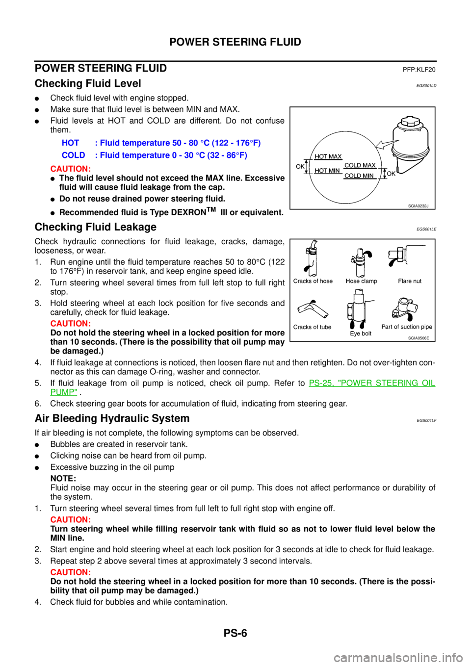
Checking Fluid LevelEGS001LD
lCheck fluid level with engine stopped.
lMake sure that fluid level is between MIN and MAX.
lFluid levels at HOT and COLD are different. Do not confuse
them.
CAUTION:
lThe fluid level should not exceed the MAX line. Excessive
fluid will cause fluid leakage from the cap.
lDo not reuse drained power steering fluid.
lRecommended fluid is Type DEXRONTMIII or equivalent.
Checking Fluid LeakageEGS001LE
Check hydraulic connections for fluid leakage, cracks, damage,
looseness, or wear.
1. Run engine until the fluid temperature reaches 50 to 80°C(122
to 176°F) in reservoir tank, and keep engine speed idle.
2. Turn steering wheel several times from full left stop to full right
stop.
3. Hold steering wheel at each lock position for five seconds and
carefully, check for fluid leakage.
CAUTION:
Do not hold the steering wheel in a locked position for more
than 10 seconds. (There is the possibility that oil pump may
be damaged.)
4. If fluid leakage at connections is noticed, then loosen flare nut and then retighten. Do not over-tighten con-
nector as this can damage O-ring, washer and connector.
5. If fluid leakage from oil pump is noticed, check oil pump. Refer toPS-25, "
POWER STEERING OIL
PUMP".
6. Check steering gear boots for accumulation of fluid, indicating from steering gear.
Air Bleeding Hydraulic SystemEGS001LF
If air bleeding is not complete, the following symptoms can be observed.
lBubbles are created in reservoir tank.
lClicking noise can be heard from oil pump.
lExcessive buzzing in the oil pump
NOTE:
Fluid noise may occur in the steering gear or oil pump. This does not affect performance or durability of
the system.
1. Turn steering wheel several times from full left to full right stop with engine off.
CAUTION:
Turn steering wheel while filling reservoir tank with fluid so as not to lower fluid level below the
MIN line.
2. Start engine and hold steering wheel at each lock position for 3 seconds at idle to check for fluid leakage.
3. Repeat step 2 above several times at approximately 3 second intervals.
CAUTION:
Do not hold the steering wheel in a locked position for more than 10 seconds. (There is the possi-
bility that oil pump may be damaged.)
4. Check fluid for bubbles and while contamination.HOT : Fluid temperature 50 - 80°C (122 - 176°F)
COLD : Fluid temperature 0 - 30°C(32-86°F)
SGIA0232J
SGIA0506E