Page 2308 of 3171

CHASSIS AND BODY MAINTENANCE
MA-33
C
D
E
F
G
H
I
J
K
MA
B
MA
Changing Front Final Drive Oil (Front Differential Gear Oil)ELS001IU
CAUTION:
If using the vehicle for towing, the final drive oil must be replaced as specified. Refer toMA-8, "
PERI-
ODIC MAINTENANCE".
DRAINING
1. Stop the engine.
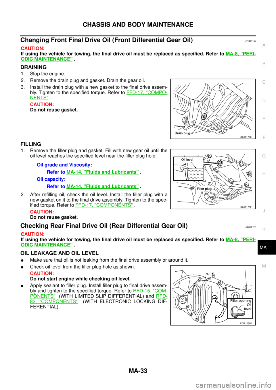
2. Remove the drain plug and gasket. Drain the gear oil.
3. Install the drain plug with a new gasket to the final drive assem-
bly. Tighten to the specified torque. Refer toFFD-17, "
COMPO-
NENTS".
CAUTION:
Do not reuse gasket.
FILLING
1. Remove the filler plug and gasket. Fill with new gear oil until the
oil level reaches the specified level near the filler plug hole.
2. After refilling oil, check the oil level. Install the filler plug with a
new gasket on it to the final drive assembly. Tighten to the spec-
ified torque. Refer toFFD-17, "
COMPONENTS".
CAUTION:
Do not reuse gasket.
Checking Rear Final Drive Oil (Rear Differential Gear Oil)ELS001IV
CAUTION:
If using the vehicle for towing, the final drive oil must be replaced as specified. Refer toMA-8, "
PERI-
ODIC MAINTENANCE".
OIL LEAKAGE AND OIL LEVEL
lMake sure that oil is not leaking from the final drive assembly or around it.
lCheck oil level from the filler plug hole as shown.
CAUTION:
Do not start engine while checking oil level.
lApply sealant to filler plug. Install filler plug to final drive assem-
bly and tighten to the specified torque. Refer toRFD-15, "
COM-
PONENTS"(WITH LIMITED SLIP DIFFERENTIAL) andRFD-
82, "COMPONENTS"(WITH ELECTRONIC LOCKING DIF-
FERENTIAL).
LDIA0175E
OilgradeandViscosity:
Refer toMA-14, "
Fluids and Lubricants".
Oil capacity:
Refer toMA-14, "
Fluids and Lubricants".
LDIA0176E
PDIA1039E
Page 2309 of 3171

MA-34
CHASSIS AND BODY MAINTENANCE
Changing Rear Final Drive Oil (Rear Differential Gear Oil)
ELS001IW
CAUTION:
If using the vehicle for towing, the final drive oil must be replaced as specified. Refer toMA-8, "
PERI-
ODIC MAINTENANCE".
DRAINING
1. Stop the engine.
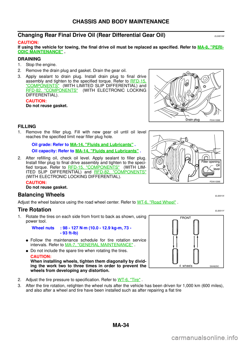
2. Remove the drain plug and gasket. Drain the gear oil.
3. Apply sealant to drain plug. Install drain plug to final drive
assembly and tighten to the specified torque. Refer toRFD-15,
"COMPONENTS"(WITH LIMITED SLIP DIFFERENTIAL) and
RFD-82, "
COMPONENTS"(WITH ELECTRONIC LOCKING
DIFFERENTIAL).
CAUTION:
Do not reuse gasket.
FILLING
1. Remove the filler plug. Fill with new gear oil until oil level
reaches the specified limit near filler plug hole.
2. After refilling oil, check oil level. Apply sealant to filler plug.
Install filler plug to final drive assembly and tighten to the speci-
fied torque. Refer toRFD-15, "
COMPONENTS"(WITH LIM-
ITED SLIP DIFFERENTIAL) andRFD-82, "
COMPONENTS"
(WITH ELECTRONIC LOCKING DIFFERENTIAL).
CAUTION:
Do not reuse gasket.
Balancing WheelsELS001IX
Adjust the wheel balance using the road wheel center. Refer toWT-6, "Road Wheel".
Tire RotationELS001IY
1. Rotate the tires on each side from front to back as shown, using
power tool.
lFollow the maintenance schedule for tire rotation service
intervals. Refer toMA-7, "
GENERAL MAINTENANCE".
lDo not include the spare tire when rotating the tires.
CAUTION:
When installing wheels, tighten them diagonally by divid-
ing the work two to three times in order to prevent the
wheels from developing any distortion.
2. Adjust the tire pressure to specification. Refer toWT-6, "
Tire".
3. After the tire rotation, retighten the wheel nuts after the vehicle has been driven for 1,000 km (600 miles),
and also after a wheel and tire have been installed such as after repairing a flat tire
PDIA1038E
Oil grade: Refer toMA-14, "Fluids and Lubricants".
Oil capacity: Refer toMA-14, "
Fluids and Lubricants".
PDIA1039E
Wheel nuts : 98 - 127 N·m (10.0 - 12.9 kg-m, 73 -
- 93 ft-lb)
SMA829C
Page 2314 of 3171
CHASSIS AND BODY MAINTENANCE
MA-39
C
D
E
F
G
H
I
J
K
MA
B
MA
Lubricating Locks, Hinges and Hood LatchesELS001J6
lLubricate the locations shown. Refer toMA-14, "Fluids and Lubricants".
MLIB0001E
Page 2340 of 3171
TRANSMISSION ASSEMBLY
MT-23
D
E
F
G
H
I
J
K
L
MA
B
MT
Shift Control Components
1. Check ball plug 2. Check ball spring 3. Check ball
4. Interlock pin 5. Interlock plunger 6. Retaining pin
7. 3rd-4th fork rod bracket 8. 3rd-4th fork rod 9. 1st-2nd fork rod
10. 1st-2nd shift fork 11. 3rd-4th fork rod (reversal side) 12. 3rd-4th shift fork
13. 5th-6th shift fork 14. 5th-6th fork rod (reversal side) 15. 5th-6th fork rod
16. 5th-6th fork rod bracket 17. 3rd-4th control lever 18. Shifter cap
19. 5th-6th control lever 20. Adapter plate
PCIB1597E
Page 2347 of 3171
MT-30
TRANSMISSION ASSEMBLY
5. Remove 3rd-4th control lever mounting bolts, and then remove
3rd-4th control lever and shifter cap from adapter plate.
6. Remove retaining pin using a pin punch, and then remove 3rd -
4th fork rod bracket and 3rd-4th fork rod from adapter plate.
7. Remove check balls and interlock pin from adapter plate.
8. Remove retaining pin using a pin punch, and then remove 3rd-
4th shift fork and 3rd-4th fork rod (reversal side) from adapter
plate.
9. Remove retaining pin using a pin punch, and then remove 1st-
2nd shift fork and 1st-2nd fork rod from adapter plate.
PCIB1232E
PCIB0145E
PCIB0146E
PCIB0601E
PCIB0602E
Page 2348 of 3171
TRANSMISSION ASSEMBLY
MT-31
D
E
F
G
H
I
J
K
L
MA
B
MT
10. Remove interlock plunger and interlock pin from adapter plate.
11. Remove retaining pin using a pin punch, and then remove
reverse shift fork and reverse fork rod from adapter plate.
12. Remove check balls from adapter plate.
13. Remove retaining pin using a pin punch, and then remove 5th-
6th fork rod bracket and 5th-6th fork rod from adapter plate.
14. Remove 5th-6th control lever mounting bolts, and then remove
5th-6th control lever from adapter plate.
PCIB0147E
SCIA1447E
PCIB0148E
PCIB0239E
PCIB1233E
Page 2355 of 3171

MT-38
TRANSMISSION ASSEMBLY
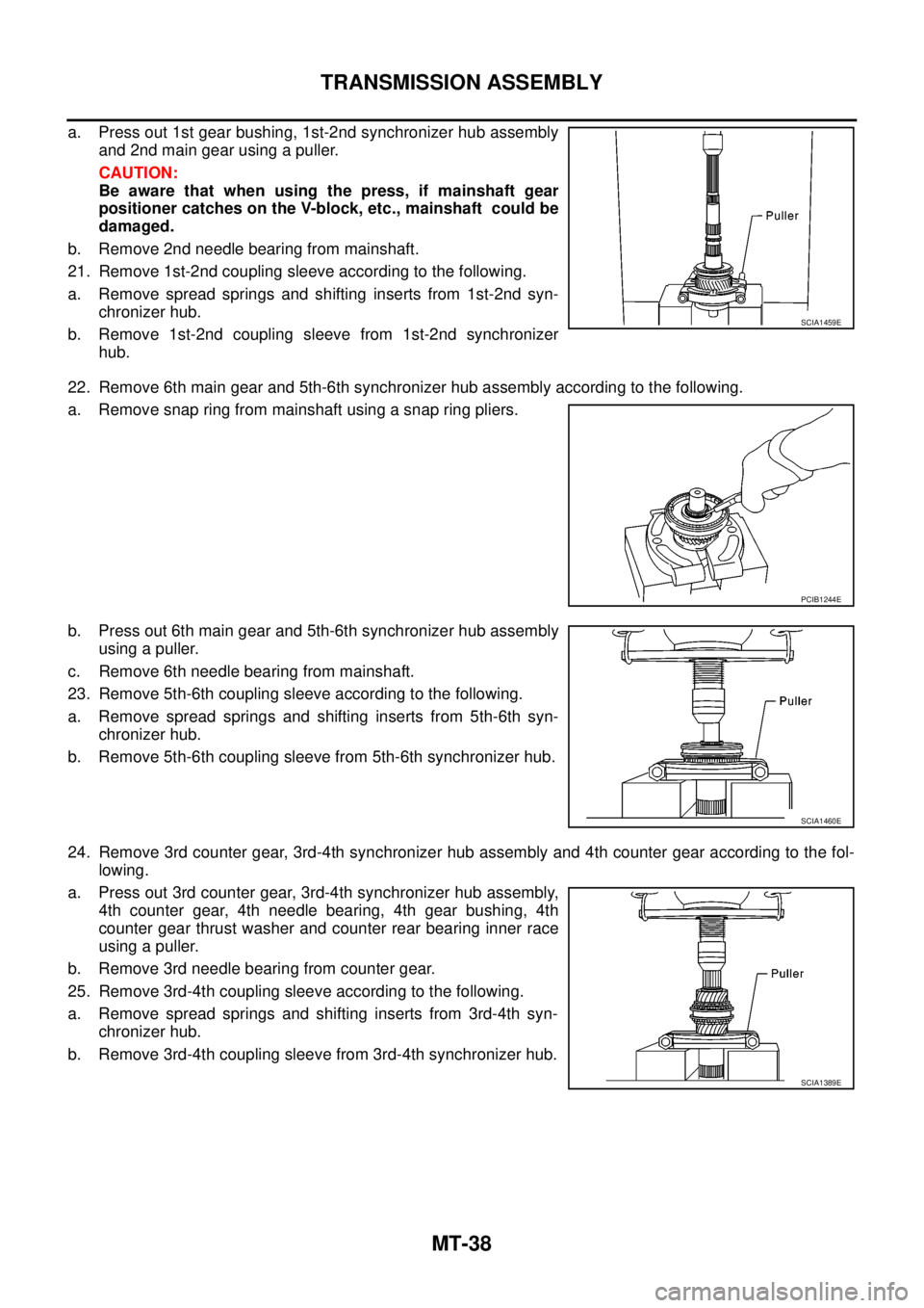
a. Press out 1st gear bushing, 1st-2nd synchronizer hub assembly
and 2nd main gear using a puller.
CAUTION:
Be aware that when using the press, if mainshaft gear
positioner catches on the V-block, etc., mainshaft could be
damaged.
b. Remove 2nd needle bearing from mainshaft.
21. Remove 1st-2nd coupling sleeve according to the following.
a. Remove spread springs and shifting inserts from 1st-2nd syn-
chronizer hub.
b. Remove 1st-2nd coupling sleeve from 1st-2nd synchronizer
hub.
22. Remove 6th main gear and 5th-6th synchronizer hub assembly according to the following.
a. Remove snap ring from mainshaft using a snap ring pliers.
b. Press out 6th main gear and 5th-6th synchronizer hub assembly
using a puller.
c. Remove 6th needle bearing from mainshaft.
23. Remove 5th-6th coupling sleeve according to the following.
a. Remove spread springs and shifting inserts from 5th-6th syn-
chronizer hub.
b. Remove 5th-6th coupling sleeve from 5th-6th synchronizer hub.
24. Remove 3rd counter gear, 3rd-4th synchronizer hub assembly and 4th counter gear according to the fol-
lowing.
a. Press out 3rd counter gear, 3rd-4th synchronizer hub assembly,
4th counter gear, 4th needle bearing, 4th gear bushing, 4th
counter gear thrust washer and counter rear bearing inner race
using a puller.
b. Remove 3rd needle bearing from counter gear.
25. Remove 3rd-4th coupling sleeve according to the following.
a. Remove spread springs and shifting inserts from 3rd-4th syn-
chronizer hub.
b. Remove 3rd-4th coupling sleeve from 3rd-4th synchronizer hub.
SCIA1459E
PCIB1244E
SCIA1460E
SCIA1389E
Page 2370 of 3171
TRANSMISSION ASSEMBLY
MT-53
D
E
F
G
H
I
J
K
L
MA
B
MT
a. Instal bearing retainer to adapter plate.
b. Apply recommended thread locking sealant to threads of bolts,
and then tighten mounting bolts to the specified torque. Refer to
MT-19, "
Case Components".
25. Install reverse synchronizer hub assembly according to the following.
a. Install reverse coupling sleeve to reverse synchronizer hub.
CAUTION:
lDo not reuse reverse coupling sleeve and reverse synchronizer hub.
lReplace reverse coupling sleeve and reverse synchronizer hub as a set.
lBe careful with the orientation reverse coupling sleeve.
lBe careful with the orientation reverse synchronizer hub.
b. Install spread springs to shifting inserts to reverse synchronizer
hub.
CAUTION:
lDo not install spread spring hook onto the same shifting
insert.
PCIB1238E
PCIB0617E
PCIB1267E
SCIA1600E