Page 2169 of 3171
LT-86
FRONT FOG LAMP
Bulb Replacement
EKS00P4E
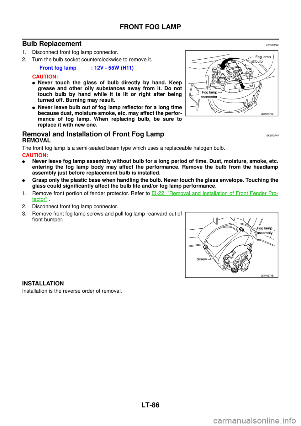
1. Disconnect front fog lamp connector.
2. Turn the bulb socket counterclockwise to remove it.
CAUTION:
lNever touch the glass of bulb directly by hand. Keep
grease and other oily substances away from it. Do not
touch bulb by hand while it is lit or right after being
turned off. Burning may result.
lNever leave bulb out of fog lamp reflector for a long time
because dust, moisture smoke, etc. may affect the perfor-
mance of fog lamp. When replacing bulb, be sure to
replace it with new one.
Removal and Installation of Front Fog LampEKS00P4F
REMOVAL
The front fog lamp is a semi-sealed beam type which uses a replaceable halogen bulb.
CAUTION:
lNever leave fog lamp assembly without bulb for a long period of time. Dust, moisture, smoke, etc.
entering the fog lamp body may affect the performance. Remove the bulb from the headlamp
assembly just before replacement bulb is installed.
lGrasp only the plastic base when handling the bulb. Never touch the glass envelope. Touching the
glass could significantly affect the bulb life and/or fog lamp performance.
1. Remove front portion of fender protector. Refer toEI-22, "
Removal and Installation of Front Fender Pro-
tector".
2. Disconnect front fog lamp connector.
3. Remove front fog lamp screws and pull fog lamp rearward out of
front bumper.
INSTALLATION
Installation is the reverse order of removal.Front fog lamp : 12V - 55W (H11)
LKIA0573E
LKIA0574E
Page 2170 of 3171
REAR FOG LAMP
LT-87
C
D
E
F
G
H
I
J
L
MA
B
LT
REAR FOG LAMPPFP:26550
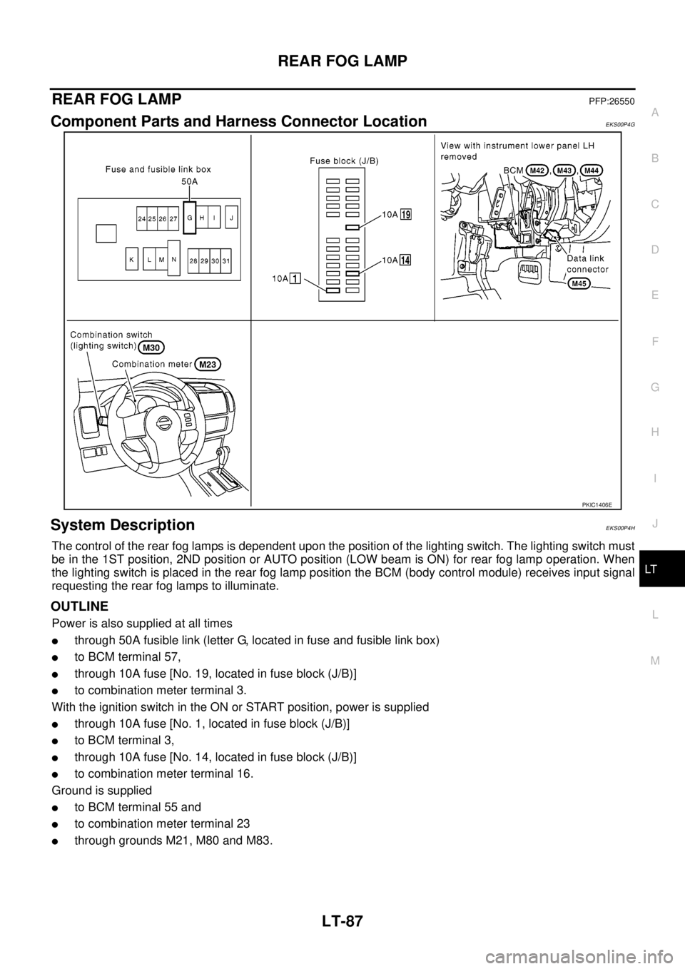
Component Parts and Harness Connector LocationEKS00P4G
System DescriptionEKS00P4H
The control of the rear fog lamps is dependent upon the position of the lighting switch. The lighting switch must
be in the 1ST position, 2ND position or AUTO position (LOW beam is ON) for rear fog lamp operation. When
the lighting switch is placed in the rear fog lamp position the BCM (body control module) receives input signal
requesting the rear fog lamps to illuminate.
OUTLINE
Power is also supplied at all times
lthrough 50A fusible link (letter G, located in fuse and fusible link box)
lto BCM terminal 57,
lthrough 10A fuse [No. 19, located in fuse block (J/B)]
lto combination meter terminal 3.
With the ignition switch in the ON or START position, power is supplied
lthrough 10A fuse [No. 1, located in fuse block (J/B)]
lto BCM terminal 3,
lthrough 10A fuse [No. 14, located in fuse block (J/B)]
lto combination meter terminal 16.
Ground is supplied
lto BCM terminal 55 and
lto combination meter terminal 23
lthrough grounds M21, M80 and M83.
PKIC1406E
Page 2180 of 3171
TURN SIGNAL AND HAZARD WARNING LAMPS
LT-97
C
D
E
F
G
H
I
J
L
MA
B
LT
TURN SIGNAL AND HAZARD WARNING LAMPSPFP:26120
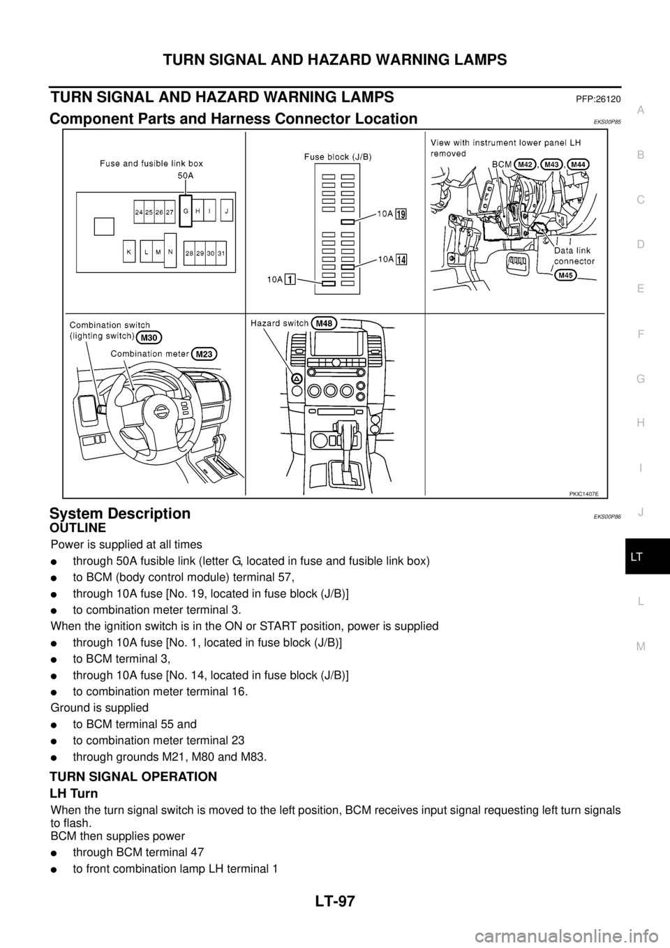
Component Parts and Harness Connector LocationEKS00P85
System DescriptionEKS00P86
OUTLINE
Power is supplied at all times
lthrough 50A fusible link (letter G, located in fuse and fusible link box)
lto BCM (body control module) terminal 57,
lthrough 10A fuse [No. 19, located in fuse block (J/B)]
lto combination meter terminal 3.
When the ignition switch is in the ON or START position, power is supplied
lthrough 10A fuse [No. 1, located in fuse block (J/B)]
lto BCM terminal 3,
lthrough 10A fuse [No. 14, located in fuse block (J/B)]
lto combination meter terminal 16.
Ground is supplied
lto BCM terminal 55 and
lto combination meter terminal 23
lthrough grounds M21, M80 and M83.
TURN SIGNAL OPERATION
LH Turn
When the turn signal switch is moved to the left position, BCM receives input signal requesting left turn signals
to flash.
BCM then supplies power
lthrough BCM terminal 47
lto front combination lamp LH terminal 1
PKIC1407E
Page 2181 of 3171

LT-98
TURN SIGNAL AND HAZARD WARNING LAMPS
lto side turn signal lamp LH terminal 1 and
lto rear combination lamp LH terminal 2.
Ground is supplied
lto front combination lamp LH terminal 2
lto side turn signal lamp LH terminal 2 and
lto rear combination lamp LH terminal 3
lthrough ground E21, E41 and E61.
The BCM also supplies input to combination meter terminals 11 and 12 through the CAN communication. This
input is processed by unified meter control unit in combination meter, which in turn supplies ground to the left
turn signal indicator lamp.
With power and input supplied, BCM controls flashing of LH turn signal lamps.
RH Turn
When the turn signal switch is moved to the right position, BCM receives input signal requesting right turn sig-
nals to flash.
BCM then supplies power
lthrough BCM terminal 48
lto front combination lamp RH terminal 1
lto side turn signal lamp RH terminal 1 and
lto rear combination lamp RH terminal 2.
Ground is supplied
lto front combination lamp RH terminal 2
lto side turn signal lamp RH terminal 2 and
lto rear combination lamp RH terminal 3
lthrough ground E21, E41 and E61.
The BCM also supplies input to combination meter terminals 11 and 12 through the CAN communication. This
input is processed by unified meter control unit in combination meter, which in turn supplies ground to the right
turn signal indicator lamp.
With power and input supplied, BCM controls flashing of RH turn signal lamps.
HAZARD LAMP OPERATION
Power is supplied at all times
lthrough 50A fusible link (letter G, located in fuse and fusible link box)
lto BCM terminal 57,
lthrough 10A fuse [No. 19, located in fuse block (J/B)]
lto combination meter terminal 3.
Ground is supplied
lto BCM terminal 55 and
lto combination meter terminal 23
lthrough grounds M21, M80 and M83.
When the hazard switch is depressed, ground is supplied
lto BCM terminal 33
lthrough hazard switch terminal 2
lthrough hazard switch terminal 1
lthrough grounds M21, M80 and M83.
When the hazard switch is depressed, BCM receives input signal requesting turn signals to flash.
BCM then supplies power
lthrough BCM terminal 47
lto front combination lamp LH terminal 1
lto side turn signal lamp LH terminal 1 and
lto rear combination lamp LH terminal 2,
lthrough BCM terminal 48
Page 2194 of 3171
TURN SIGNAL AND HAZARD WARNING LAMPS
LT-111
C
D
E
F
G
H
I
J
L
MA
B
LT
Bulb Replacement (Front Turn Signal Lamp)EKS00P8G
Refer toLT-29, "Bulb Replacement".
Bulb Replacement (Rear Turn Signal Lamp)EKS00P8H
Refer toLT- 1 4 3 , "Bulb Replacement".
Bulb Replacement (Side Turn Signal Lamp)EKS00P8I
1. Remove side turn signal lamp. Refer toLT- 111 , "Removal and
Installation of Side Turn Signal Lamp".
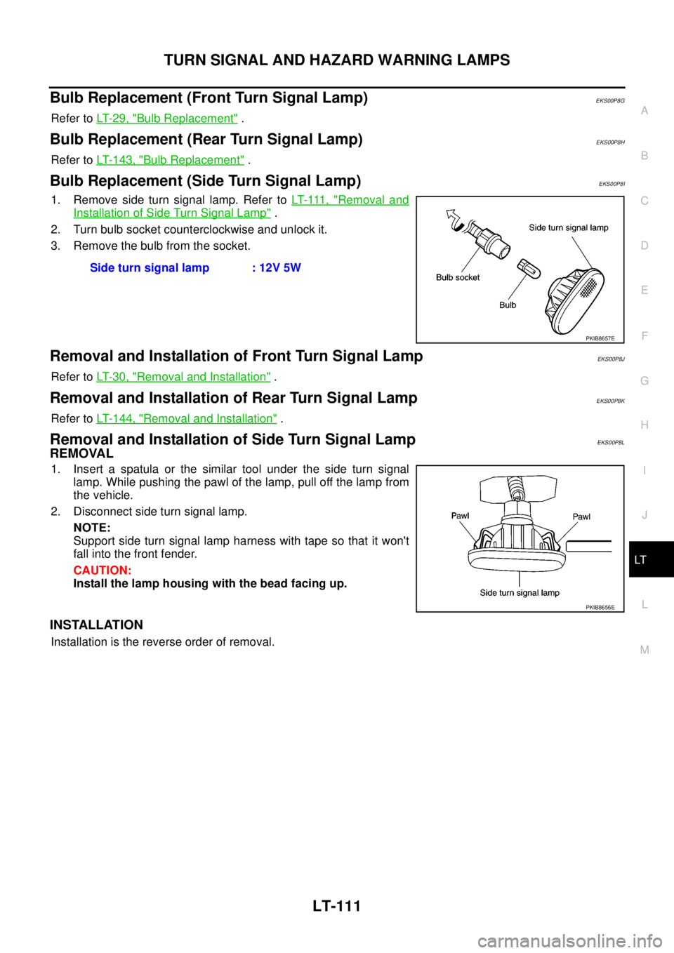
2. Turn bulb socket counterclockwise and unlock it.
3. Remove the bulb from the socket.
Removal and Installation of Front Turn Signal LampEKS00P8J
Refer toLT-30, "Removal and Installation".
Removal and Installation of Rear Turn Signal LampEKS00P8K
Refer toLT- 1 4 4 , "Removal and Installation".
Removal and Installation of Side Turn Signal LampEKS00P8L
REMOVAL
1. Insert a spatula or the similar tool under the side turn signal
lamp. While pushing the pawl of the lamp, pull off the lamp from
the vehicle.
2. Disconnect side turn signal lamp.
NOTE:
Support side turn signal lamp harness with tape so that it won't
fall into the front fender.
CAUTION:
Install the lamp housing with the bead facing up.
INSTALLATION
Installation is the reverse order of removal.Side turn signal lamp : 12V 5W
PKIB8657E
PKIB8656E
Page 2208 of 3171
PARKING, LICENSE PLATE AND TAIL LAMPS
LT-125
C
D
E
F
G
H
I
J
L
MA
B
LT
PARKING, LICENSE PLATE AND TAIL LAMPSPFP:26550
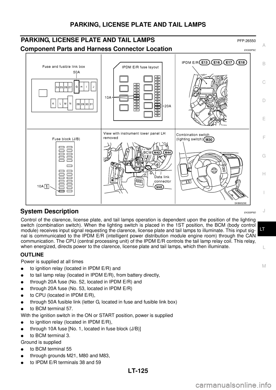
Component Parts and Harness Connector LocationEKS00P9C
System DescriptionEKS00P9D
Control of the clarence, license plate, and tail lamps operation is dependent upon the position of the lighting
switch (combination switch). When the lighting switch is placed in the 1ST position, the BCM (body control
module) receives input signal requesting the clarence, license plate and tail lamps to illuminate. This input sig-
nal is communicated to the IPDM E/R (intelligent power distribution module engine room) through the CAN
communication. The CPU (central processing unit) of the IPDM E/R controls the tail lamp relay coil. This relay,
when energized, directs power to the clarence, license plate and tail lamps, which then illuminate.
OUTLINE
Power is supplied at all times
lto ignition relay (located in IPDM E/R) and
lto tail lamp relay (located in IPDM E/R), from battery directly,
lthrough 20A fuse (No. 52, located in IPDM E/R) and
lthrough 20A fuse (No. 53, located in IPDM E/R)
lto CPU (located in IPDM E/R),
lthrough 50A fusible link (letter G, located in fuse and fusible link box)
lto BCM terminal 57.
With the ignition switch in the ON or START position, power is supplied
lto ignition relay (located in IPDM E/R),
lthrough 10A fuse [No. 1, located in fuse block (J/B)]
lto BCM terminal 3.
Ground is supplied
lto BCM terminal 55
lthrough grounds M21, M80 and M83,
lto IPDM E/R terminals 38 and 59
SKIB6529E
Page 2226 of 3171
REAR COMBINATION LAMP
LT-143
C
D
E
F
G
H
I
J
L
MA
B
LT
REAR COMBINATION LAMPPFP:26554
Bulb ReplacementEKS00P90
REMOVAL
1. Remove rear combination lamp. Refer toLT- 1 4 4 , "Removal and Installation".
2. Turn bulb socket (1), (2) and (3) counterclockwise and unlock it.
3. Remove bulb (4), (5) and (6).
INSTALLATION
Installation is the reverse order of removal.Stop/taillamp :12V-21/5W
Rear turn signal lamp : 12V - 21W
Buck up lamp (or rear fog lamp) : 12V - 16W (21W)
SKIB6852E
Page 2228 of 3171
INTERIOR ROOM LAMP
LT-145
C
D
E
F
G
H
I
J
L
MA
B
LT
INTERIOR ROOM LAMPPFP:26410
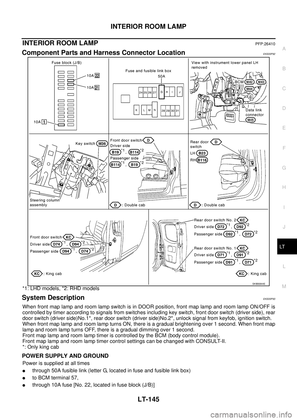
Component Parts and Harness Connector LocationEKS00P92
*1: LHD models, *2: RHD models
System DescriptionEKS00P93
When front map lamp and room lamp switch is in DOOR position, front map lamp and room lamp ON/OFF is
controlled by timer according to signals from switches including key switch, front door switch (driver side), rear
door switch (driver side)No.1*, rear door switch (driver side)No.2*, unlock signal from keyfob, ignition switch.
When front map lamp and room lamp turns ON, there is a gradual brightening over 1 second. When front map
lamp and room lamp turns OFF, there is a gradual dimming over 1 second.
Front map lamp and room lamp timer is controlled by the BCM (body control module).
Front map lamp and room lamp timer control settings can be changed with CONSULT-II.
*: Only king cab
POWER SUPPLY AND GROUND
Power is supplied at all times
lthrough 50A fusible link (letter G, located in fuse and fusible link box)
lto BCM terminal 57,
lthrough 10A fuse [No. 22, located in fuse block (J/B)]
SKIB6844E