2005 NISSAN NAVARA lock
[x] Cancel search: lockPage 2229 of 3171
![NISSAN NAVARA 2005 Repair Workshop Manual LT-146
INTERIOR ROOM LAMP
lto key switch terminal 2,
lthrough 10A fuse [No. 21, located in fuse block (J/B)]
lto BCM terminal 41.
When key is inserted in key switch, power is supplied
lthrough the key NISSAN NAVARA 2005 Repair Workshop Manual LT-146
INTERIOR ROOM LAMP
lto key switch terminal 2,
lthrough 10A fuse [No. 21, located in fuse block (J/B)]
lto BCM terminal 41.
When key is inserted in key switch, power is supplied
lthrough the key](/manual-img/5/57362/w960_57362-2228.png)
LT-146
INTERIOR ROOM LAMP
lto key switch terminal 2,
lthrough 10A fuse [No. 21, located in fuse block (J/B)]
lto BCM terminal 41.
When key is inserted in key switch, power is supplied
lthrough the key switch terminal 1
lto BCM terminal 5.
With ignition switch in the ON or START position, power is supplied
lthrough 10A fuse [No. 1, located in fuse and block (J/B)]
lto BCM terminal 3.
Ground is supplied
lto BCM terminal 55
lthrough grounds M21, M80 and M83.
When front driver side door is opened, ground is supplied (double cab)
lto BCM terminal 15
lthrough front door switch driver side terminal 2
lthrough case ground of front door switch driver side.
When front passenger side door is opened, ground is supplied (double cab)
lto BCM terminal 14
lthrough front door switch passenger side terminal 2
lthrough case ground of front door switch passenger side.
When rear door LH is opened, ground is supplied (double cab)
lto BCM terminal 16
lthrough rear door switch LH terminal 2
lthrough case ground of rear door switch LH.
When rear door RH is opened, ground is supplied (double cab)
lto BCM terminal 12
lthrough rear door switch RH terminal 2
lthrough case ground of rear door switch RH.
When front driver side door is opened, ground is supplied (king cab)
lto BCM terminal 15
lthrough front door switch (driver side) terminal 2
lthrough front door switch (driver side) terminal 3
lthrough grounds B9 and B25 (LHD models)
lthrough grounds B106 and B121 (RHD models).
When front passenger side door is opened, ground is supplied (king cab)
lto BCM terminal 14
lthrough front door switch (passenger side) terminal 2
lthrough front door switch (passenger side) terminal 3
lthrough grounds B9 and B25 (LHD models)
lthrough grounds B106 and B121 (RHD models).
When rear door (driver side) is opened, ground is supplied (king cab)
lto BCM terminal 15
lthrough rear door switch (driver side) No.1 and No.2 terminals 1
lthrough rear door switch (driver side) No.1 and No.2 terminals 2
lthrough grounds B9 and B25 (LHD models)
lthrough grounds B106 and B121 (RHD models).
When rear door (passenger side) is opened, ground is supplied (king cab)
lto BCM terminal 14
lthrough rear door switch (passenger side) No.1 and No.2 terminals 1
Page 2230 of 3171

INTERIOR ROOM LAMP
LT-147
C
D
E
F
G
H
I
J
L
MA
B
LT
lthrough rear door switch (passenger side) No.1 and No.2 terminals 2
lthrough grounds B9 and B25 (LHD models)
lthrough grounds B106 and B121 (RHD models).
When a signal is received by BCM, power is supplied
lthrough BCM terminal 42
lto key ring lamp terminal 1
lto front map lamp terminal 1 and
lto room lamp terminal 2.
SWITCH OPERATION
When front map lamp switch is ON, ground is supplied
lto front map lamp terminal 2
lthrough grounds M21, M80 and M83.
When room lamp switch is ON, ground is supplied through room lamp case ground.
ROOM LAMP TIMER OPERATION
When lamp switch is in DOOR position, and when all conditions below are met, BCM performs timer control
(maximum 30 seconds) for interior room lamp and map lamp ON/OFF.
Power is supplied
lthrough 10A fuse [No. 22, located in fuse block (J/B)]
lto key switch terminal 2.
Key is removed from ignition key cylinder (key switch OFF), power will not be supplied to BCM terminal 5.
At the time that driver's door is opened, BCM detects that driver's door is unlocked. It determines that room
lamp timer operation conditions are met, and turns the interior room lamps ON for 30 seconds.
Key is in ignition key cylinder (key switch ON), power is supplied
lthrough key switch terminal 1
lto BCM terminal 5.
When key is removed from key switch (key switch OFF), power supply to BCM terminal 5 is terminated. BCM
detects that key has been removed, determines that room lamp timer conditions are met, and turns the interior
room lamps ON for 30 seconds.
When driver's door opens®closes, and the key is not inserted in the key switch (key switch OFF), BCM ter-
minal 15 changes between 0V (door open)®12V (door closed). The BCM determines that conditions for
room lamp operation are met and turns the room lamp ON for 30 seconds.
Timer control is canceled under the following conditions.
lDriver's door is opened [front door switch (driver side)].
lIgnition switch ON.
lKeyfob
INTERIOR LAMP BATTERY SAVER CONTROL
If interior lamp is left ON, it will not be turned off even when door is closed.
BCM turns off interior lamp automatically to save battery 30 minutes after ignition switch is turned off.
BCM controls interior lamps listed below:
lFront map lamp
lRoom lamp
lKey ring lamp
After lamps turn OFF by the battery saver system, the lamps illuminate again when
lsignal received from keyfob or key cylinder is locked or unlocked,
ldoor is opened or closed,
lkey is removed from ignition key cylinder or inserted in ignition key cylinder.
Interior lamp battery saver control period can be changed by the function setting of CONSULT-II. Refer toLT-
158, "WORK SUPPORT".
Page 2241 of 3171

LT-158
INTERIOR ROOM LAMP
4. Touch “INT LAMP” on “SELECT SYSTEM” screen.
WORK SUPPORT
Operation Procedure
1. Touch “INT LAMP” on “SELECT SYSTEM” screen.
2. Touch “WORK SUPPORT” on “SELECT DIAG MODE” screen.
3. Touch “SET I/L D-UNLCK INTCON” on “SELECT WORK ITEM” screen.
4. Touch “START”.
5. Touch “CHANGE SETT”.
6. The setting will be changed and “CUSTOMIZING COMPLETED” will be displayed.
7. Touch “END”.
Display Item List
Reference between “MODE” and “TIME” for “TURN ON/OFF”.
DATA MONITOR
Operation Procedure
1. Touch “INT LAMP” on “SELECT TEST ITEM” screen.
2. Touch “DATA MONITOR” on “SELECT DIAG MODE” screen.
3. Touch either “ALL SIGNALS” or “SELECTION FROM MENU” on “SELECT MONITOR ITEM” screen.
4. When “ALL SIGNALS” is selected, all the items will be monitored. When “SELECTION FROM MENU” is
selected, touch items to be monitored.
5. Touch “START”.
6. Touch “RECORD” while monitoring, then the status of the monitored item can be recorded. To stop
recording, touch “STOP”.
PKIC0325E
Item Description CONSULT-II
SET I/L D-UNLCK INTCONThe 30 seconds operating function of the interior room lamps and the ignition key-
hole illumination can be selected when driver's door is released (unlocked).ON/OFF
ROOM LAMP ON TIME SETThe time in order to escalate illumination can be selected when the interior room
lamps and the ignition keyhole illumination is turned on.MODE 1 - 7
ROOM LAMP OFF TIME SETThe time in order to diminish illumination can be selected when the interior room
lamps and the ignition keyhole illumination is turned off.MODE 1 - 7
MODE 1 2 3 4 5 6 7
Time (sec.) 0.5 1 2 3 4 5 0
ALL SIGNALS Monitors all the signals.
SELECTION FROM MENU Selects and monitors the individual signal.
Page 2242 of 3171

INTERIOR ROOM LAMP
LT-159
C
D
E
F
G
H
I
J
L
MA
B
LT
Display Item List
ACTIVE TEST
Operation Procedure
1. Touch “INT LAMP” on “SELECT TEST ITEM” screen.
2. Touch “ACTIVE TEST” on “SELECT DIAG MODE” screen.
3. Touch item to be tested and check operation of the selected item.
4. During the operation check, touching “OFF” deactivates the operation.
Display Item List
Monitor item Contents
IGN ON SW “ON/OFF” Displays “IGN position (ON)/OFF, ACC position (OFF)” judged from the ignition switch signal.
KEY ON SW “ON/OFF” Displays “Key inserted (ON)/key removed (OFF)” status judged from the key switch signal.
DOOR SW-DR “ON/OFF”Displays status of the driver's door as judged from the driver door switch signal. (Door is open:
ON/Door is closed: OFF)
DOOR SW-AS “ON/OFF”Displays “Door open (ON)/Door closed (OFF)” status, determined from passenger's door switch
signal.
DOOR SW-RR “ON/OFF”Displays “Door open (ON)/Door closed (OFF)” status, determined from rear door switch RH sig-
nal.
DOOR SW-RL “ON/OFF”Displays “Door open (ON)/Door closed (OFF)” status, determined from rear door switch LH sig-
nal.
BACK DOOR SW “ON/OFF” Displays “Door open (ON)/Door closed (OFF)” status, determined from back door switch signal.
KEY CYL LK-SW “ON/OFF” Displays “Door locked (ON)” status, determined from key cylinder lock switch in driver door.
KEY CYL UN-SW “ON/OFF” Displays “Door unlocked (OFF)” status, determined from key cylinder lock switch in driver door.
CDL LOCK SW “ON/OFF”Displays “Door locked (ON)/Door unlocked (OFF)” status, determined from locking detection
switch in driver door.
CDL UNLOCK SW “ON/OFF”Displays “Door unlocked (OFF)” status, determined from locking detection switch in passenger
door.
Test item Description
INT LAMP Interior room lamp can be operated by any ON-OFF operations.
Page 2245 of 3171

LT-162
ILLUMINATION
ILLUMINATION
PFP:27545
System DescriptionEKS00P8V
Control of the illumination lamps operation is dependent upon the position of the lighting switch (combination
switch). When the lighting switch is placed in the 1ST position, 2ND position or AUTO position (headlamp is
ON) the BCM (body control module) receives input signal requesting the illumination lamps to illuminate. This
input signal is communicated to the IPDM E/R (intelligent power distribution module engine room) through the
CAN communication. The CPU (central processing unit) of the IPDM E/R controls the tail lamp relay coil. This
relay, when energized, directs power to the illumination lamps, which then illuminate.
Power is supplied at all times
lto ignition relay (located in IPDM E/R) and
lto tail lamp relay (located in IPDM E/R), from battery directly,
lthrough 50A fusible link (letter G, located in fuse and fusible link box)
lto BCM terminal 57,
lthrough 20A fuse (No. 52, located in IPDM E/R) and
lthrough 20A fuse (No. 53, located in IPDM E/R)
lto CPU (located in IPDM E/R),
lthrough 10A fuse [No.19, located in fuse block (J/B)]
lto combination meter terminal 3.
With the ignition switch in the ON or START position, power is supplied
lto ignition relay (located in IPDM E/R),
lthrough 10A fuse [No. 1, located in fuse block (J/B)]
lto BCM terminal 3,
lthrough 10A fuse [No. 14, located in fuse block (J/B)]
lto combination meter 16.
Ground is supplied
lto BCM terminal 55 and
lto combination meter terminal 23
lthrough grounds M21, M80 and M83,
lto IPDM E/R terminals 38 and 59
lthrough grounds E21, E41 and E61.
ILLUMINATION OPERATION BY LIGHTING SWITCH
With the lighting switch in the 1ST position, 2ND position or AUTO position (headlamp is ON), the BCM
receives input signal requesting the illumination lamps to illuminate. This input signal is communicated to the
IPDM E/R through the CAN communication. The CPU of the IPDM E/R controls the tail lamp relay coil, which,
when energized, directs power
lthrough 10A fuse (No. 37, located in IPDM E/R)
lthrough IPDM E/R terminal 57
lto hazard switch (illumination) terminal 3
lto 4WD shift switch (illumination) terminal 7 (with 4-wheel drive)
lto front air control (illumination) terminal 8
lto audio unit (illumination) terminal 2 (1CD player)
lto audio unit (illumination) terminal 8 (6CD player)
lto AV switch (illumination) terminal 3 (with NAVI)
lto audio unit (illumination) terminal 29 (with NAVI)
lto glove box lamp terminal 1
lto A/T device (illumination) terminal 3 (with A/T)
lto heat up switch (illumination) terminal 5
lto DIFF LOCK switch (illumination) terminal 4 (with DIFF LOCK)
lto heated seat switch (driver side) (illumination) terminal 5 (with heated seats)
lto heated seat switch (passenger side) (illumination) terminal 5 (with heated seats)
Page 2246 of 3171

ILLUMINATION
LT-163
C
D
E
F
G
H
I
J
L
MA
B
LT
lto cigarette lighter (illumination) terminal 1
lto ashtray (illumination) terminal 1
lto headlamp washer switch (illumination) terminal 3
lto headlamp aiming switch (illumination) terminal 3 and
lto NAVI control unit (illumination) terminal 61 (with NAVI).
Ground is supplied
lto hazard switch (illumination) terminal 4
lto 4WD shift switch (illumination) terminal 8 (with 4-wheel drive)
lto front air control (illumination) terminal 9
lto AV switch (illumination) terminal 4 (with NAVI)
lto audio unit (illumination) terminal 28 (with NAVI)
lto DIFF LOCK switch (illumination) terminal 5 (with DIFF LOCK)
lto heated seat switch (driver side) (illumination) terminal 6 (with heated seats) and
lto heated seat switch (passenger side) (illumination) terminal 6 (with heated seats)
lthrough combination meter terminal 22
lthrough combination meter terminal 23
lthrough ground M21, M80 and M83,
lto glove box lamp terminal 2
lto A/T device (illumination) terminal 5 (with A/T)
lto heat up switch (illumination) terminal 6
lto ashtray (illumination) terminal 2
lto headlamp washer switch (illumination) terminal 4 and
lto headlamp aiming switch (illumination) terminal 4
ltrough ground M21, M80 and M83,
lto audio unit (illumination) (1CD and 6CD player)
lthrough case ground of audio unit,
lto cigarette lighter (illumination)
lthrough case ground of cigarette lighter,
lto NAVI control unit (illumination) terminal 1 (with NAVI)
lthrough ground B106 and B121.
With power and ground supplied, illumination lamps illuminate.
CAN Communication System DescriptionEKS00P8W
Refer toLAN-23, "CAN COMMUNICATION".
CAN Communication UnitEKS00P8X
Refer toLAN-30, "CAN Communication Unit".
Page 2260 of 3171

PREPARATION
LU-3
C
D
E
F
G
H
I
J
K
L
MA
LU
PREPARATIONPFP:00002
Special Service ToolsEBS01E53
Commercial Service ToolsEBS01E54
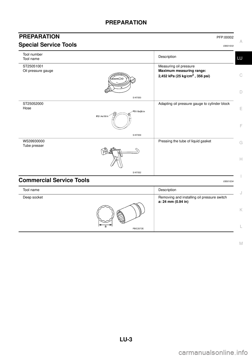
Tool number
Tool nameDescription
ST25051001
Oil pressure gaugeMeasuring oil pressure
Maximum measuring range:
2,452 kPa (25 kg/cm
2, 356 psi)
ST25052000
HoseAdapting oil pressure gauge to cylinder block
WS39930000
Tube presserPressing the tube of liquid gasket
S-NT050
S-NT559
S-NT052
Tool nameDescription
Deep socketRemoving and installing oil pressure switch
a: 24 mm (0.94 in)
PBIC2072E
Page 2262 of 3171

ENGINE OIL
LU-5
C
D
E
F
G
H
I
J
K
L
MA
LU
ENGINE OILPFP:KLA92
InspectionEBS01E56
ENGINE OIL LEVEL
NOTE:
Before starting engine, put vehicle horizontally and check the engine oil level. If engine is already started, stop
it and allow 10 minutes before checking.
1. Pull out oil level gauge and wipe it clean.
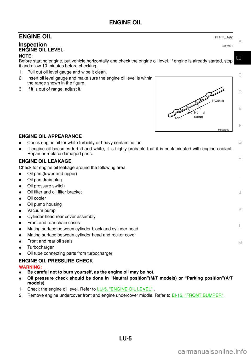
2. Insert oil level gauge and make sure the engine oil level is within
the range shown in the figure.
3. If it is out of range, adjust it.
ENGINE OIL APPEARANCE
lCheck engine oil for white turbidity or heavy contamination.
lIf engine oil becomes turbid and white, it is highly probable that it is contaminated with engine coolant.
Repair or replace damaged parts.
ENGINE OIL LEAKAGE
Check for engine oil leakage around the following area.
lOil pan (lower and upper)
lOil pan drain plug
lOil pressure switch
lOil filter and oil filter bracket
lOil cooler
lOil pump housing
lVa c u u m p u m p
lCylinder head rear cover assembly
lFront and rear chain cases
lMating surface between cylinder block and cylinder head
lMating surface between cylinder head and rocker cover
lFront and rear oil seals
lTurbocharger
lOil tube connecting parts from turbocharger
ENGINE OIL PRESSURE CHECK
WARNING:
lBe careful not to burn yourself, as the engine oil may be hot.
lOil pressure check should be done in “Neutral position”(M/T models) or “Parking position”(A/T
models).
1. Check the engine oil level. Refer toLU-5, "
ENGINE OIL LEVEL".
2. Remove engine undercover front and engine undercover middle. Refer toEI-15, "
FRONT BUMPER".
PBIC2823E