2005 NISSAN NAVARA lock
[x] Cancel search: lockPage 2375 of 3171
MT-58
TRANSMISSION ASSEMBLY
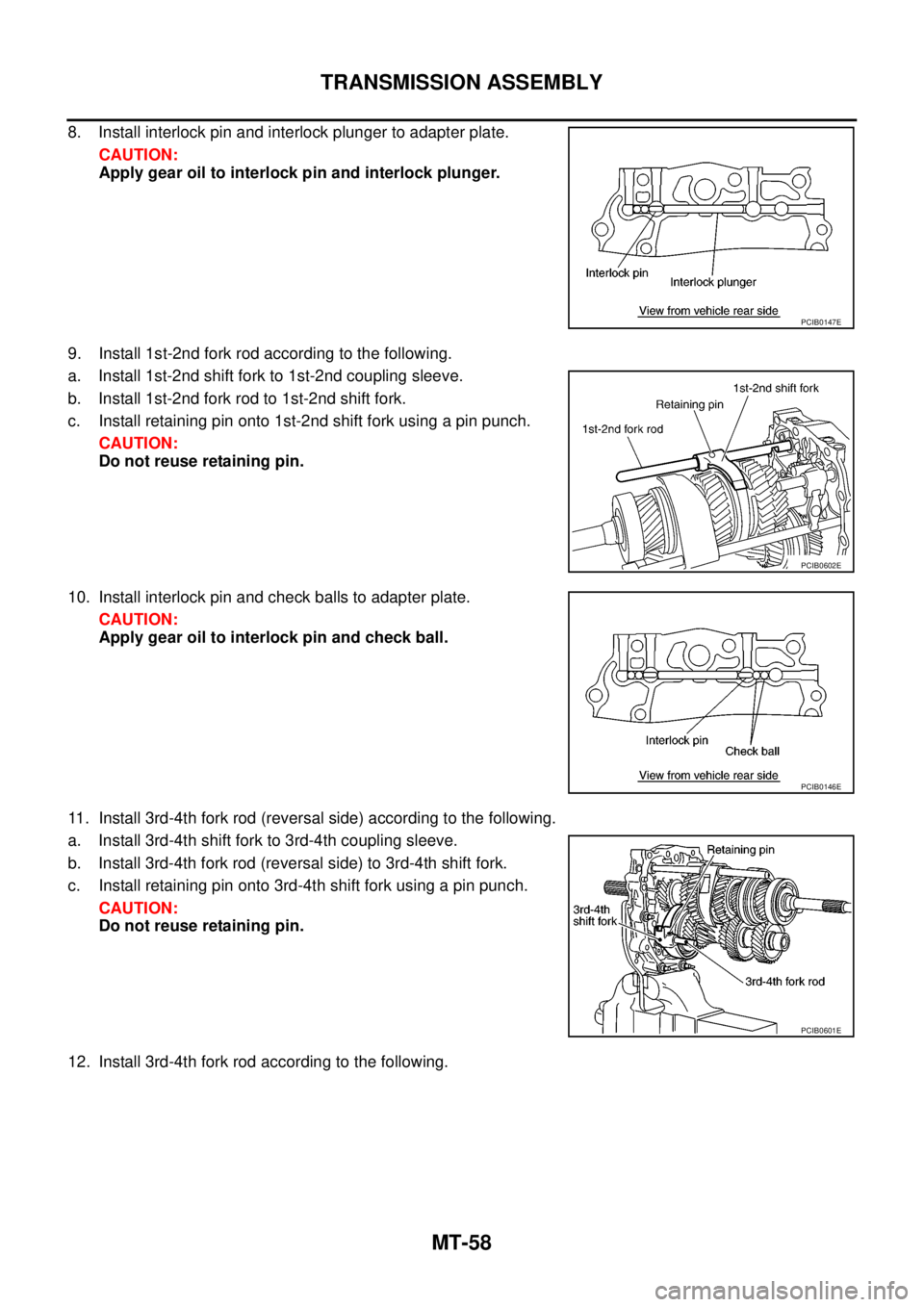
8. Install interlock pin and interlock plunger to adapter plate.
CAUTION:
Apply gear oil to interlock pin and interlock plunger.
9. Install 1st-2nd fork rod according to the following.
a. Install 1st-2nd shift fork to 1st-2nd coupling sleeve.
b. Install 1st-2nd fork rod to 1st-2nd shift fork.
c. Install retaining pin onto 1st-2nd shift fork using a pin punch.
CAUTION:
Do not reuse retaining pin.
10. Install interlock pin and check balls to adapter plate.
CAUTION:
Apply gear oil to interlock pin and check ball.
11. Install 3rd-4th fork rod (reversal side) according to the following.
a. Install 3rd-4th shift fork to 3rd-4th coupling sleeve.
b. Install 3rd-4th fork rod (reversal side) to 3rd-4th shift fork.
c. Install retaining pin onto 3rd-4th shift fork using a pin punch.
CAUTION:
Do not reuse retaining pin.
12. Install 3rd-4th fork rod according to the following.
PCIB0147E
PCIB0602E
PCIB0146E
PCIB0601E
Page 2401 of 3171
MTC-14
PRECAUTIONS
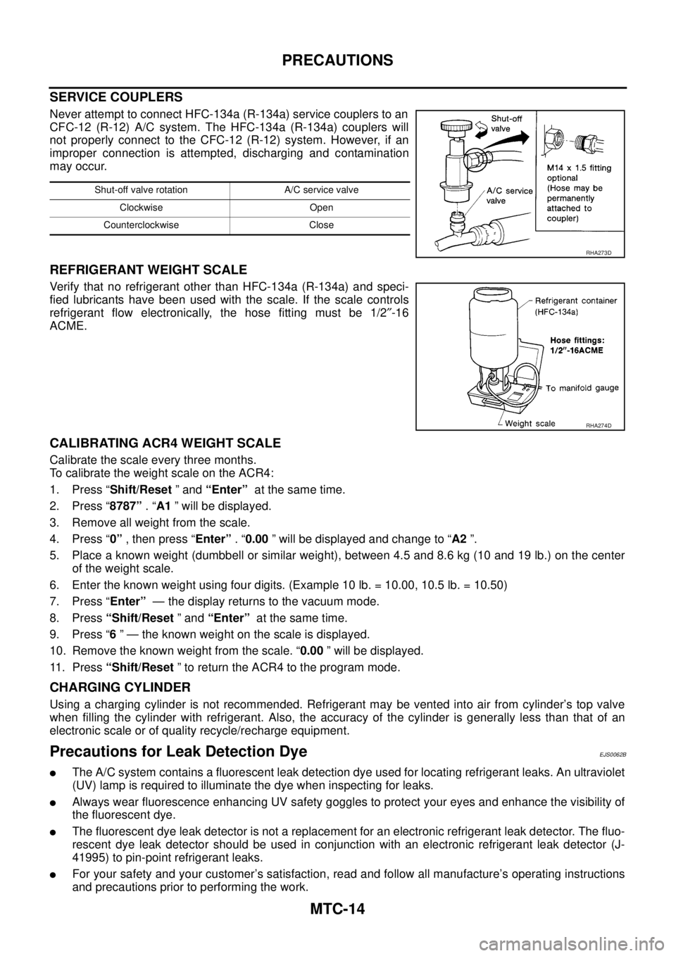
SERVICE COUPLERS
Never attempt to connect HFC-134a (R-134a) service couplers to an
CFC-12 (R-12) A/C system. The HFC-134a (R-134a) couplers will
not properly connect to the CFC-12 (R-12) system. However, if an
improper connection is attempted, discharging and contamination
may occur.
REFRIGERANT WEIGHT SCALE
Verify that no refrigerant other than HFC-134a (R-134a) and speci-
fied lubricants have been used with the scale. If the scale controls
refrigerant flow electronically, the hose fitting must be 1/2²-16
ACME.
CALIBRATING ACR4 WEIGHT SCALE
Calibrate the scale every three months.
To calibrate the weight scale on the ACR4:
1. Press “Shift/Reset”and“Enter”at the same time.
2. Press “8787”.“A1” will be displayed.
3. Remove all weight from the scale.
4. Press “0”, then press “Enter”.“0.00” will be displayed and change to “A2”.
5. Place a known weight (dumbbell or similar weight), between 4.5 and 8.6 kg (10 and 19 lb.) on the center
of the weight scale.
6. Enter the known weight using four digits. (Example 10 lb. = 10.00, 10.5 lb. = 10.50)
7. Press “Enter”— the display returns to the vacuum mode.
8. Press“Shift/Reset”and“Enter”at the same time.
9. Press “6” — the known weight on the scale is displayed.
10. Remove the known weight from the scale. “0.00” will be displayed.
11. Press“Shift/Reset” to return the ACR4 to the program mode.
CHARGING CYLINDER
Using a charging cylinder is not recommended. Refrigerant may be vented into air from cylinder’s top valve
when filling the cylinder with refrigerant. Also, the accuracy of the cylinder is generally less than that of an
electronic scale or of quality recycle/recharge equipment.
Precautions for Leak Detection DyeEJS0062B
lThe A/C system contains a fluorescent leak detection dye used for locating refrigerant leaks. An ultraviolet
(UV) lamp is required to illuminate the dye when inspecting for leaks.
lAlways wear fluorescence enhancing UV safety goggles to protect your eyes and enhance the visibility of
the fluorescent dye.
lThe fluorescent dye leak detector is not a replacement for an electronic refrigerant leak detector. The fluo-
rescent dye leak detector should be used in conjunction with an electronic refrigerant leak detector (J-
41995) to pin-point refrigerant leaks.
lFor your safety and your customer’s satisfaction, read and follow all manufacture’s operating instructions
and precautions prior to performing the work.
Shut-off valve rotation A/C service valve
Clockwise Open
Counterclockwise Close
RHA273D
RHA274D
Page 2413 of 3171

MTC-26
AIR CONDITIONER CONTROL
AIR CONDITIONER CONTROL
PFP:27500
DescriptionEJS005FW
The front air control provides regulation of the vehicle's interior temperature. The system is based on the posi-
tion of the front air controls temperature switch selected by the driver. This is done by utilizing a microcom-
puter, also referred to as the front air control, which receives input signals from the following three sensors:
lIntake sensor
lPBR (Position Balanced Resistor).
The front air control uses these signals (including the set position of the temperature switch) to control:
lOutlet air volume
lAir temperature
lAir distribution
The front air control is used to select:
lOutlet air volume
lAir temperature/distribution
OperationEJS005FX
AIR MIX DOOR CONTROL
The air mix door is controlled so that in-vehicle temperature changed based on the position of the temperature
switch.
BLOWER SPEED CONTROL
Blower speed is controlled based on front blower switch settings.
When blower switch is turned, the blower motor starts and increases air flow volume each time the blower
switch is turned counterclockwise, and decreases air flow volume each time the blower switch is turned coun-
terclockwise.
When engine coolant temperature is low, the blower motor operation is delayed to prevent cool air from flow-
ing.
INTAKE DOORS CONTROL
The intake doors are controlled by the recirculation switch setting, and the mode (defroster) switch setting.
MODE DOOR CONTROL
The mode door is controlled by the position of the mode switch.
DEFROSTER DOOR CONTROL
The defroster door is controlled by: Turning the defroster dial to front defroster.
Page 2436 of 3171
TROUBLE DIAGNOSIS
MTC-49
C
D
E
F
G
H
I
K
L
MA
B
MTC
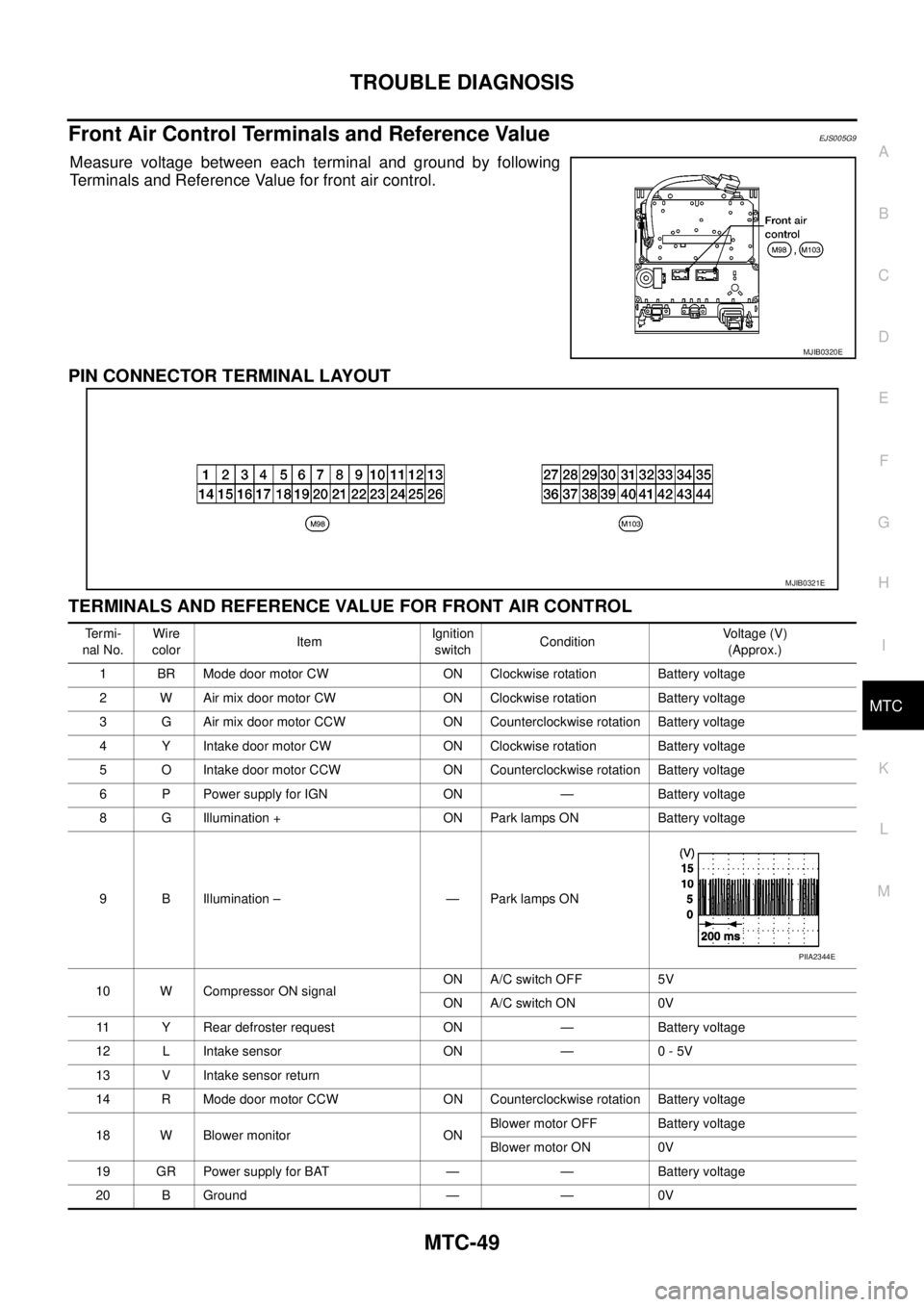
Front Air Control Terminals and Reference ValueEJS005G9
Measure voltage between each terminal and ground by following
Terminals and Reference Value for front air control.
PIN CONNECTOR TERMINAL LAYOUT
TERMINALS AND REFERENCE VALUE FOR FRONT AIR CONTROL
MJIB0320E
MJIB0321E
Te r m i -
nal No.Wire
colorItemIgnition
switchConditionVoltage (V)
(Approx.)
1 BR Mode door motor CW ON Clockwise rotation Battery voltage
2 W Air mix door motor CW ON Clockwise rotation Battery voltage
3 G Air mix door motor CCW ON Counterclockwise rotation Battery voltage
4 Y Intake door motor CW ON Clockwise rotation Battery voltage
5 O Intake door motor CCW ON Counterclockwise rotation Battery voltage
6 P Power supply for IGN ON — Battery voltage
8 G Illumination + ON Park lamps ON Battery voltage
9 B Illumination – — Park lamps ON
10 W Compressor ON signalON A/C switch OFF 5V
ON A/C switch ON 0V
11 Y Rear defroster request ON — Battery voltage
12 L Intake sensor ON — 0 - 5V
13 V Intake sensor return
14 R Mode door motor CCW ON Counterclockwise rotation Battery voltage
18 W Blower monitor ONBlower motor OFF Battery voltage
Blower motor ON 0V
19 GR Power supply for BAT — — Battery voltage
20 B Ground — — 0V
PIIA2344E
Page 2440 of 3171
TROUBLE DIAGNOSIS
MTC-53
C
D
E
F
G
H
I
K
L
MA
B
MTC
Operational CheckEJS005GB
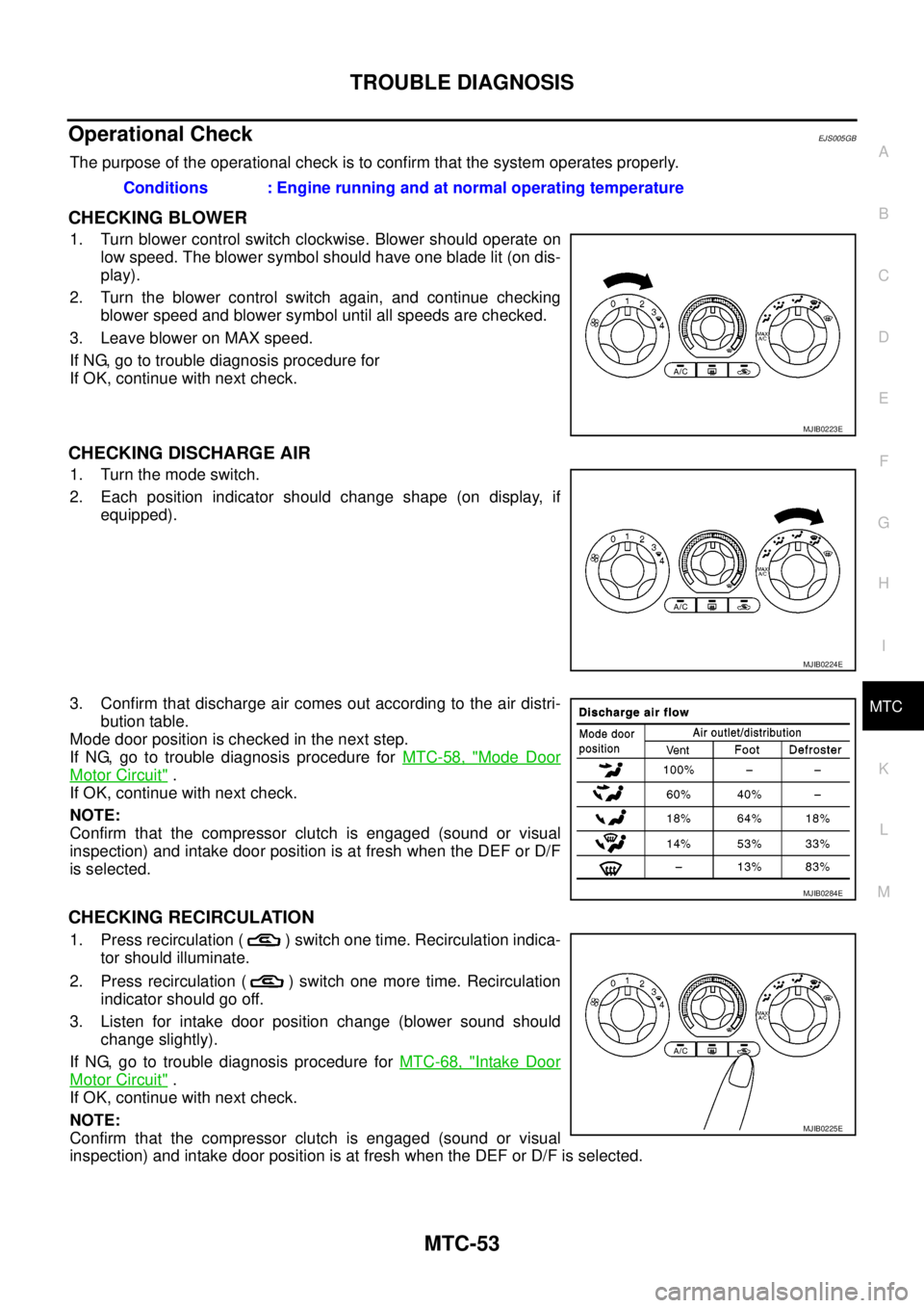
The purpose of the operational check is to confirm that the system operates properly.
CHECKING BLOWER
1. Turn blower control switch clockwise. Blower should operate on
low speed. The blower symbol should have one blade lit (on dis-
play).
2. Turn the blower control switch again, and continue checking
blower speed and blower symbol until all speeds are checked.
3. Leave blower on MAX speed.
If NG, go to trouble diagnosis procedure for
If OK, continue with next check.
CHECKING DISCHARGE AIR
1. Turn the mode switch.
2. Each position indicator should change shape (on display, if
equipped).
3. Confirm that discharge air comes out according to the air distri-
bution table.
Mode door position is checked in the next step.
If NG, go to trouble diagnosis procedure forMTC-58, "
Mode Door
Motor Circuit".
If OK, continue with next check.
NOTE:
Confirm that the compressor clutch is engaged (sound or visual
inspection) and intake door position is at fresh when the DEF or D/F
is selected.
CHECKING RECIRCULATION
1. Press recirculation ( ) switch one time. Recirculation indica-
tor should illuminate.
2. Press recirculation ( ) switch one more time. Recirculation
indicator should go off.
3. Listen for intake door position change (blower sound should
change slightly).
If NG, go to trouble diagnosis procedure forMTC-68, "
Intake Door
Motor Circuit".
If OK, continue with next check.
NOTE:
Confirm that the compressor clutch is engaged (sound or visual
inspection) and intake door position is at fresh when the DEF or D/F is selected.Conditions : Engine running and at normal operating temperature
MJIB0223E
MJIB0224E
MJIB0284E
MJIB0225E
Page 2441 of 3171
MTC-54
TROUBLE DIAGNOSIS
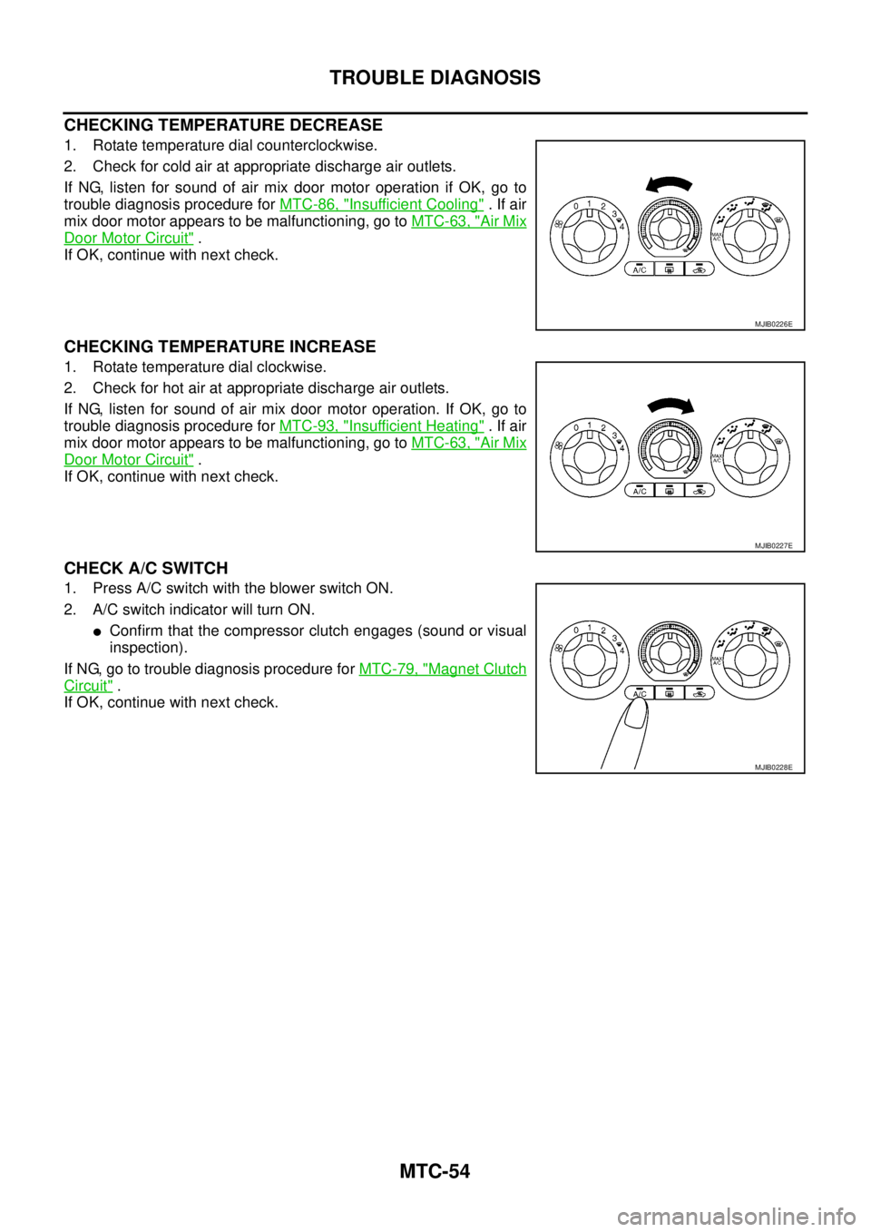
CHECKING TEMPERATURE DECREASE
1. Rotate temperature dial counterclockwise.
2. Check for cold air at appropriate discharge air outlets.
If NG, listen for sound of air mix door motor operation if OK, go to
trouble diagnosis procedure forMTC-86, "
Insufficient Cooling".Ifair
mix door motor appears to be malfunctioning, go toMTC-63, "
Air Mix
Door Motor Circuit".
If OK, continue with next check.
CHECKING TEMPERATURE INCREASE
1. Rotate temperature dial clockwise.
2. Check for hot air at appropriate discharge air outlets.
If NG, listen for sound of air mix door motor operation. If OK, go to
trouble diagnosis procedure forMTC-93, "
Insufficient Heating".Ifair
mix door motor appears to be malfunctioning, go toMTC-63, "
Air Mix
Door Motor Circuit".
If OK, continue with next check.
CHECK A/C SWITCH
1. Press A/C switch with the blower switch ON.
2. A/C switch indicator will turn ON.
lConfirm that the compressor clutch engages (sound or visual
inspection).
If NG, go to trouble diagnosis procedure forMTC-79, "
Magnet Clutch
Circuit".
If OK, continue with next check.
MJIB0226E
MJIB0227E
MJIB0228E
Page 2444 of 3171
TROUBLE DIAGNOSIS
MTC-57
C
D
E
F
G
H
I
K
L
MA
B
MTC
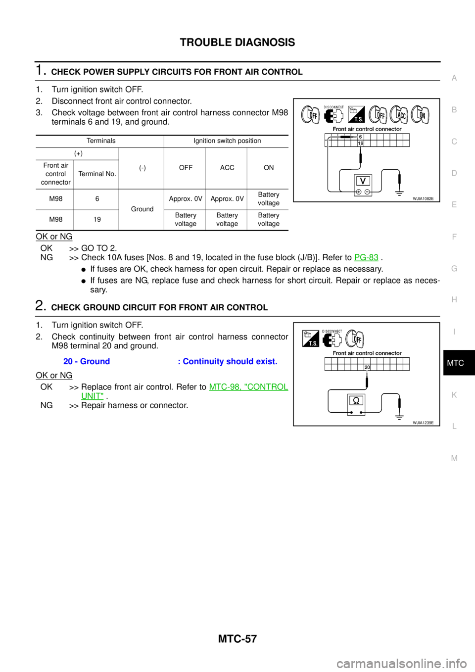
1.CHECK POWER SUPPLY CIRCUITS FOR FRONT AIR CONTROL
1. Turn ignition switch OFF.
2. Disconnect front air control connector.
3. Check voltage between front air control harness connector M98
terminals 6 and 19, and ground.
OK or NG
OK >> GO TO 2.
NG >> Check 10A fuses [Nos. 8 and 19, located in the fuse block (J/B)]. Refer toPG-83
.
lIf fuses are OK, check harness for open circuit. Repair or replace as necessary.
lIf fuses are NG, replace fuse and check harness for short circuit. Repair or replace as neces-
sary.
2.CHECK GROUND CIRCUIT FOR FRONT AIR CONTROL
1. Turn ignition switch OFF.
2. Check continuity between front air control harness connector
M98 terminal 20 and ground.
OK or NG
OK >> Replace front air control. Refer toMTC-98, "CONTROL
UNIT".
NG >> Repair harness or connector.
Terminals Ignition switch position
(+)
(-) OFF ACC ON Front air
control
connectorTerminal No.
M98 6
GroundApprox. 0V Approx. 0VBattery
voltage
M98 19Battery
voltageBattery
voltageBattery
voltage
WJIA1082E
20 - Ground : Continuity should exist.
WJIA1239E
Page 2479 of 3171
MTC-92
TROUBLE DIAGNOSIS
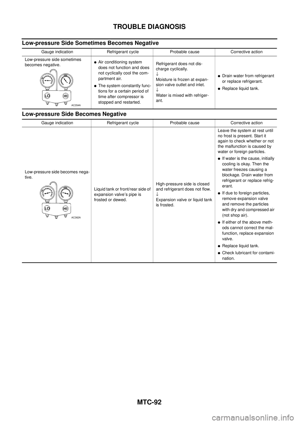
Low-pressure Side Sometimes Becomes Negative
Low-pressure Side Becomes Negative
Gauge indication Refrigerant cycle Probable cause Corrective action
Low-pressure side sometimes
becomes negative.
lAir conditioning system
does not function and does
not cyclically cool the com-
partment air.
lThe system constantly func-
tions for a certain period of
time after compressor is
stopped and restarted.Refrigerant does not dis-
charge cyclically.
¯
Moisture is frozen at expan-
sion valve outlet and inlet.
¯
Water is mixed with refriger-
ant.
lDrain water from refrigerant
or replace refrigerant.
lReplace liquid tank.
AC354A
Gauge indication Refrigerant cycle Probable cause Corrective action
Low-pressure side becomes nega-
tive.
Liquid tank or front/rear side of
expansion valve¢spipeis
frosted or dewed.High-pressure side is closed
and refrigerant does not flow.
¯
Expansion valve or liquid tank
is frosted.Leave the system at rest until
no frost is present. Start it
again to check whether or not
the malfunction is caused by
waterorforeignparticles.
lIf water is the cause, initially
cooling is okay. Then the
water freezes causing a
blockage. Drain water from
refrigerant or replace refrig-
erant.
lIf due to foreign particles,
remove expansion valve
and remove the particles
with dry and compressed air
(not shop air).
lIf either of the above meth-
ods cannot correct the mal-
function, replace expansion
valve.
lReplace liquid tank.
lCheck lubricant for contami-
nation.
AC362A