2005 NISSAN NAVARA lock
[x] Cancel search: lockPage 2693 of 3171

RF-16
SUNROOF
Work Flow
EIS00D52
1. Check the symptom and customer's requests.
2. Understand the outline of system. Refer toRF-11, "
System Description".
3. According to the trouble diagnosis chart, repair or replace the cause of the malfunction. Refer toRF-16,
"Trouble Diagnosis Symptom Chart".
4. Does sunroof system operate normally? If Yes, GO TO 5. If No, GO TO 3.
5. INSPECTION END.
Trouble Diagnosis Symptom ChartEIS00D53
BCM Power Supply and Ground Circuit CheckEIS00D54
1.FUSE INSPECTION
Check the following.
l50A fusible link (letterG, located in the fuse and fusible link box)
l10A fuse [No. 1, located in the fuse block (J/B)]
l10A fuse [No.21 located in the fuse block (J/B)]
NOTE:
Refer toRF-10, "
Component Parts and Harness Connector Location".
OK or NG
OK >> GO TO 2.
NG >> If fuse is blown, be sure to eliminate cause of malfunction before installing new fuse, refer toPG-
4, "POWER SUPPLY ROUTING CIRCUIT".
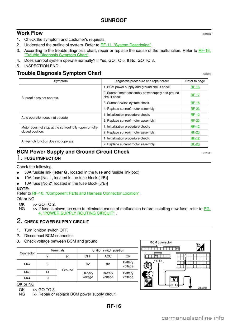
2.CHECK POWER SUPPLY CIRCUIT
1. Turn ignition switch OFF.
2. Disconnect BCM connector.
3. Check voltage between BCM and ground.
OK or NG
OK >> GO TO 3.
NG >> Repair or replace BCM power supply circuit.
Symptom Diagnostic procedure and repair order Refer to page
Sunroof does not operate.1. BCM power supply and ground circuit checkRF-16
2. Sunroof motor assembly power supply and ground
circuit checkRF-17
3. Sunroof switch system checkRF-18
4. Replace sunroof motor assembly.RF-23
Auto operation does not operate1. Initialization procedure check.RF-122. Replace sunroof motor assembly.RF-23
Motor does not stop at the sunroof fully -open or fully-
closed position.1. Initialization procedure check.RF-12
2. Replace sunroof motor assembly.RF-23
Anti-pinch function does not operate.1. Initialization procedure check.RF-122. Replace sunroof motor assembly.RF-23
ConnectorTerminals Ignition switch position
(+) (-) OFF ACC ON
M42 3
Ground0V 0VBattery
voltage
M43 41
Battery
voltageBattery
voltageBattery
voltage
M44 57
MIIB0823E
Page 2704 of 3171

RFD-1
REAR FINAL DRIVE
D DRIVELINE/AXLE
CONTENTS
C
E
F
G
H
I
J
K
L
M
SECTIONRFD
A
B
RFD
REAR FINAL DRIVE
WITH LIMITED SLIP DIFFERENTIAL
PRECAUTIONS .......................................................... 3
Limited Slip Differential (LSD) Performance Judge-
ment ......................................................................... 3
METHOD FOR TROUBLESHOOTING ................. 3
Service Notice or Precautions .................................. 3
PREPARATION ........................................................... 4
Special Service Tools ............................................... 4
Commercial Service Tools ........................................ 5
NOISE, VIBRATION, AND HARSHNESS (NVH)
TROUBLESHOOTING ................................................ 7
NVH Troubleshooting Chart ..................................... 7
DESCRIPTION ............................................................ 8
Cross-Sectional View ............................................... 8
DIFFERENTIAL GEAR OIL ........................................ 9
Changing Differential Gear Oil ................................. 9
DRAINING ............................................................. 9
FILLING ................................................................. 9
Checking Differential Gear Oil .................................. 9
OIL LEAKAGE AND OIL LEVEL ........................... 9
FRONT OIL SEAL .................................................... 10
Removal and Installation ........................................ 10
REMOVAL ........................................................... 10
INSTALLATION .................................................... 11
CARRIER COVER .................................................... 13
Removal and Installation ........................................ 13
REMOVAL ........................................................... 13
INSTALLATION ................................................... 13
REAR FINAL DRIVE ASSEMBLY ............................ 14
Removal and Installation ........................................ 14
REMOVAL ........................................................... 14
INSTALLATION ................................................... 14
Disassembly and Assembly ................................... 15
COMPONENTS .................................................. 15
ASSEMBLY INSPECTION AND ADJUSTMENT... 16
DISASSEMBLY ................................................... 19
INSPECTION AFTER DISASSEMBLY ............... 22
SELECTION ADJUSTING WASHERS ............... 23
ASSEMBLY ......................................................... 24SERVICE DATA AND SPECIFICATIONS (SDS) ...... 31
General Specifications ............................................ 31
Inspection and Adjustment ..................................... 31
PRELOAD TORQUE ........................................... 31
BACKLASH ......................................................... 31
COMPANION FLANGE RUNOUT ....................... 31
SELECTIVE PARTS ............................................ 32
WITH ELECTRONIC LOCKING DIFFEREN-
TIAL
PRECAUTIONS ........................................................ 33
Precautions for Supplemental Restraint System
(SRS)“AIRBAG”and“SEATBELTPRE-TEN-
SIONER” ................................................................. 33
Precautions for Differential Case Assembly and Dif-
ferential Lock Control Unit Replacement ................ 33
CHECK DIFF LOCK INDICATOR LAMP ............. 33
METHOD FOR ADJUSTMENT ........................... 34
Precautions ............................................................. 34
Service Notice or Precaution .................................. 35
Wiring Diagrams and Trouble Diagnosis ................ 35
PREPARATION ......................................................... 36
Special Service Tools ............................................. 36
Commercial Service Tools ...................................... 37
NOISE, VIBRATION AND HARSHNESS (NVH)
TROUBLESHOOTING .............................................. 39
NVH Troubleshooting Chart ................................... 39
DIFFERENTIAL GEAR OIL ...................................... 40
Changing Differential Gear Oil ................................ 40
DRAINING ........................................................... 40
FILLING ............................................................... 40
Checking Differential Gear Oil ................................ 40
OIL LEAKAGE AND OIL LEVEL ......................... 40
DIFFERENTIAL LOCK SYSTEM .............................. 41
Cross-sectional View .............................................. 41
Differential Lock Operation ..................................... 42
System Description ................................................. 42
DIFFERENTIAL LOCK SOLENOID .................... 42
DIFFERENTIAL LOCK POSITION SWITCH ....... 42
Page 2705 of 3171

RFD-2
DIFFERENTIAL LOCK CONTROL UNIT ............ 42
DIFFERENTIAL LOCK MODE SWITCH ............. 42
DIFF LOCK INDICATOR LAMP ........................... 42
System Diagram ..................................................... 43
COMPONENTS FUNCTION DESCRIPTION ...... 43
CAN Communication .............................................. 43
SYSTEM DESCRIPTION .................................... 43
TROUBLE DIAGNOSIS ............................................ 44
Fail-safe Function ................................................... 44
How to Perform Trouble Diagnosis ......................... 44
BASIC CONCEPT ............................................... 44
Location of Electrical Parts ..................................... 45
Wiring Diagram — DIFLOC — ................................ 46
Trouble Diagnosis Chart for Symptoms .................. 48
Differential Lock Control Unit Input/Output Signal
Reference Values ................................................... 48
DIFFERENTIAL LOCK CONTROL UNIT
INSPECTION TABLE .......................................... 48
CONSULT-II Function (DIFF LOCK) ....................... 50
FUNCTION .......................................................... 50
CONSULT-II SETTING PROCEDURE ................ 50
SELF-DIAG RESULTS MODE ............................. 51
DATA MONITOR MODE ...................................... 53
TROUBLE DIAGNOSIS FOR SYSTEM .................... 54
Power Supply Circuit For Differential Lock Control
Unit ......................................................................... 54
CONSULT-II REFERENCE VALUE IN DATA
MONITOR MODE ................................................ 54
DIFFERENTIAL LOCK CONTROL UNIT TER-
MINALS AND REFERENCE VALUE ................... 54
DIAGNOSTIC PROCEDURE .............................. 55
Differential Lock Control Unit .................................. 56
DIAGNOSTIC PROCEDURE .............................. 56
Differential Lock Mode Switch ................................ 56
CONSULT-II REFERENCE VALUE IN DATA
MONITOR MODE ................................................ 56
DIFFERENTIAL LOCK CONTROL UNIT TER-
MINALS AND REFERENCE VALUE ................... 56
DIAGNOSTIC PROCEDURE .............................. 57
COMPONENT INSPECTION .............................. 59
Differential Lock Position Switch ............................. 60
CONSULT-II REFERENCE VALUE IN DATA
MONITOR MODE ................................................ 60
DIFFERENTIAL CONTROL UNIT TERMINALS
AND REFERENCE VALUE ................................. 60
DIAGNOSTIC PROCEDURE .............................. 61
COMPONENT INSPECTION .............................. 63
Differential Lock Solenoid Relay ............................. 63
CONSULT-II REFERENCE VALUE IN DATA
MONITOR MODE ................................................ 63DIAGNOSTIC PROCEDURE ............................... 63
Differential Lock Solenoid ....................................... 64
CONSULT-II REFERENCE VALUE IN DATA
MONITOR MODE ................................................ 64
DIFFERENTIAL LOCK CONTROL UNIT TER-
MINALS AND REFERENCE VALUE ................... 64
DIAGNOSTIC PROCEDURE ............................... 65
COMPONENT INSPECTION ............................... 68
ABS System ............................................................ 68
DIAGNOSTIC PROCEDURE ............................... 68
CAN Communication Line ....................................... 69
DIAGNOSTIC PROCEDURE ............................... 69
TROUBLE DIAGNOSIS FOR SYMPTOMS .............. 70
DIFF LOCK Indicator Lamp Does Not Turn ON ...... 70
DIAGNOSTIC PROCEDURE ............................... 70
DIFF LOCK Indicator Lamp Does Not Change ....... 73
DIAGNOSTIC PROCEDURE ............................... 73
DIFF LOCK Indicator Lamp Sometimes Flashes .... 74
DIAGNOSTIC PROCEDURE ............................... 74
DIFFERENTIAL LOCK CONTROL UNIT .................. 76
Removal and Installation ......................................... 76
REMOVAL ............................................................ 76
INSTALLATION .................................................... 76
FRONT OIL SEAL ..................................................... 77
Removal and Installation ......................................... 77
REMOVAL ............................................................ 77
INSTALLATION .................................................... 78
CARRIER COVER ..................................................... 80
Removal and Installation ......................................... 80
REMOVAL ............................................................ 80
INSTALLATION .................................................... 80
REAR FINAL DRIVE ASSEMBLY ............................. 81
Removal and Installation ......................................... 81
REMOVAL ............................................................ 81
INSTALLATION .................................................... 81
Disassembly and Assembly .................................... 82
COMPONENTS ................................................... 82
ASSEMBLY INSPECTION AND ADJUSTMENT...83
DISASSEMBLY .................................................... 86
INSPECTION AFTER DISASSEMBLY ................ 90
SELECTION ADJUSTING WASHERS ................ 90
ASSEMBLY .......................................................... 91
SERVICE DATA AND SPECIFICATIONS (SDS) ....100
General Specifications ..........................................100
Inspection and Adjustment ....................................100
PRELOAD TORQUE .........................................100
BACKLASH ........................................................100
COMPANION FLANGE RUNOUT .....................100
SELECTIVE PARTS ..........................................101
Page 2707 of 3171
![NISSAN NAVARA 2005 Repair Workshop Manual RFD-4
[WITH LIMITED SLIP DIFFERENTIAL]
PREPARATION
PREPARATION
PFP:00002
Special Service ToolsEDS003H7
Tool number
Tool nameDescription
ST3127S000
Preload gauge set
1. GG91030000
Torque wrench
2. HT62 NISSAN NAVARA 2005 Repair Workshop Manual RFD-4
[WITH LIMITED SLIP DIFFERENTIAL]
PREPARATION
PREPARATION
PFP:00002
Special Service ToolsEDS003H7
Tool number
Tool nameDescription
ST3127S000
Preload gauge set
1. GG91030000
Torque wrench
2. HT62](/manual-img/5/57362/w960_57362-2706.png)
RFD-4
[WITH LIMITED SLIP DIFFERENTIAL]
PREPARATION
PREPARATION
PFP:00002
Special Service ToolsEDS003H7
Tool number
Tool nameDescription
ST3127S000
Preload gauge set
1. GG91030000
Torque wrench
2. HT62940000 (1/2²)
Socket adapter
3. HT62900000 (3/8²)
Socket adapterInspecting pinion bearing preload and
total preload
KV40104000
Flange wrench
a: 85 mm (3.35 in) dia.
b: 65 mm (2.56 in) dia.Removing and installing drive pinion
lock nut
KV381054S0
PullerRemoving front oil seal
KV10111100
Seal cutterRemoving carrier cover
KV38108800
Adjuster toolRemoving and installing side bearing
adjuster
ST30021000
PullerRemoving drive pinion rear bearing
inner race
NT124
NT659
ZZA0601D
S-NT046
WDIA0192E
ZZA0700D
Page 2713 of 3171
![NISSAN NAVARA 2005 Repair Workshop Manual RFD-10
[WITH LIMITED SLIP DIFFERENTIAL]
FRONT OIL SEAL
FRONT OIL SEAL
PFP:38189
Removal and InstallationEDS00396
REMOVAL
1. Remove the rear propeller shaft. Refer toPR-8, "Removal and Installation".
2 NISSAN NAVARA 2005 Repair Workshop Manual RFD-10
[WITH LIMITED SLIP DIFFERENTIAL]
FRONT OIL SEAL
FRONT OIL SEAL
PFP:38189
Removal and InstallationEDS00396
REMOVAL
1. Remove the rear propeller shaft. Refer toPR-8, "Removal and Installation".
2](/manual-img/5/57362/w960_57362-2712.png)
RFD-10
[WITH LIMITED SLIP DIFFERENTIAL]
FRONT OIL SEAL
FRONT OIL SEAL
PFP:38189
Removal and InstallationEDS00396
REMOVAL
1. Remove the rear propeller shaft. Refer toPR-8, "Removal and Installation".
2. Remove the rear tires.
3. Remove rear drum brake. Refer toBR-31, "
Removal and Installation of Drum Brake Assembly".
4. Rotate the drive pinion back and forth 2 to 3 times using Tool
and record the rotating torque.
5. Remove the drive pinion lock nut and washer using Tool.
6. Put a matching mark on the thread edge of drive pinion. The
mark should be in line with the mark on companion flange.
CAUTION:
For matching mark, use paint. Do not damage drive pinion
and companion flange.
7. Remove the companion flange using suitable tool.Tool number : ST3127S000
PDIA0309E
Tool number : KV40104000
LDIA0122E
SDIA2590E
WDIA0249E
Page 2714 of 3171
![NISSAN NAVARA 2005 Repair Workshop Manual FRONT OIL SEAL
RFD-11
[WITH LIMITED SLIP DIFFERENTIAL]
C
E
F
G
H
I
J
K
L
MA
B
RFD
8. Remove the front oil seal using Tool.
CAUTION:
Do not damage axle housing.
INSTALLATION
1. Install the front oil se NISSAN NAVARA 2005 Repair Workshop Manual FRONT OIL SEAL
RFD-11
[WITH LIMITED SLIP DIFFERENTIAL]
C
E
F
G
H
I
J
K
L
MA
B
RFD
8. Remove the front oil seal using Tool.
CAUTION:
Do not damage axle housing.
INSTALLATION
1. Install the front oil se](/manual-img/5/57362/w960_57362-2713.png)
FRONT OIL SEAL
RFD-11
[WITH LIMITED SLIP DIFFERENTIAL]
C
E
F
G
H
I
J
K
L
MA
B
RFD
8. Remove the front oil seal using Tool.
CAUTION:
Do not damage axle housing.
INSTALLATION
1. Install the front oil seal into the axle housing using a suitable
tool.
CAUTION:
lDo not reuse oil seal.
lDo not incline oil seal when installing.
lApply multi-purpose grease onto oil seal lip, and gear oil
onto the circumference of oil seal.
2. Align the matching mark of the drive pinion with the mark of the
companion flange, then install the companion flange.
3. Install the washer and drive pinion lock nut. Tighten the nut until
there is zero bearing end play using Tool.
CAUTION:
Do not reuse drive pinion lock nut and washer.Tool number : KV381054S0
LDIA0124E
PDIA1040E
SDIA2590E
Tool number : KV40104000
LDIA0122E
Page 2715 of 3171
![NISSAN NAVARA 2005 Repair Workshop Manual RFD-12
[WITH LIMITED SLIP DIFFERENTIAL]
FRONT OIL SEAL
4. Rotate the drive pinion using Tool. Rotating torque should be
equaltothereadingrecordedinstep4aboveduringremoval
plus an additional 0.56 N·m NISSAN NAVARA 2005 Repair Workshop Manual RFD-12
[WITH LIMITED SLIP DIFFERENTIAL]
FRONT OIL SEAL
4. Rotate the drive pinion using Tool. Rotating torque should be
equaltothereadingrecordedinstep4aboveduringremoval
plus an additional 0.56 N·m](/manual-img/5/57362/w960_57362-2714.png)
RFD-12
[WITH LIMITED SLIP DIFFERENTIAL]
FRONT OIL SEAL
4. Rotate the drive pinion using Tool. Rotating torque should be
equaltothereadingrecordedinstep4aboveduringremoval
plus an additional 0.56 N·m (5 in-lb).
5. If the rotating torque is low, continue to tighten the drive pinion
lock nut in 6.8 N·m (5 ft-lb) increments without overtightening.
Refer toRFD-15, "
COMPONENTS". Tighten until proper rotat-
ing torque is achieved.
CAUTION:
lDo not loosen the drive pinion lock nut to decrease drive
pinion rear bearing rotating torque.
lDo not exceed specified rotating preload torque. If preload torque or rotating torque is exceeded
a new collapsible spacer must be installed.
lDo not exceed maximum tightening torque. If maximum tightening torque is reached prior to
reaching the required rotating torque, the collapsible spacer may have been damaged. Replace
the collapsible spacer.
6. Check the gear oil level. Refer toRFD-9, "
Checking Differential Gear Oil".
7. Install the remaining components in the reverse order of removal.Tool number : ST3127S000
PDIA0309E
Page 2718 of 3171
![NISSAN NAVARA 2005 Repair Workshop Manual REAR FINAL DRIVE ASSEMBLY
RFD-15
[WITH LIMITED SLIP DIFFERENTIAL]
C
E
F
G
H
I
J
K
L
MA
B
RFD
Disassembly and AssemblyEDS00399
COMPONENTS
1. Drive pinion lock nut 2. Washer 3. Companion flange
4. Front NISSAN NAVARA 2005 Repair Workshop Manual REAR FINAL DRIVE ASSEMBLY
RFD-15
[WITH LIMITED SLIP DIFFERENTIAL]
C
E
F
G
H
I
J
K
L
MA
B
RFD
Disassembly and AssemblyEDS00399
COMPONENTS
1. Drive pinion lock nut 2. Washer 3. Companion flange
4. Front](/manual-img/5/57362/w960_57362-2717.png)
REAR FINAL DRIVE ASSEMBLY
RFD-15
[WITH LIMITED SLIP DIFFERENTIAL]
C
E
F
G
H
I
J
K
L
MA
B
RFD
Disassembly and AssemblyEDS00399
COMPONENTS
1. Drive pinion lock nut 2. Washer 3. Companion flange
4. Front oil seal 5. Front bearing thrust washer 6. Drive pinion front bearing
7. Axle housing 8. Breather 9. Drain plug
10. Side bearing cap 11. Adjuster lock plate 12. Carrier cover
13. Filler plug 14. Bracket 15. Drive pinion
16. Drive pinion height adjusting washer 17. Drive pinion rear bearing 18. Collapsible spacer
19. Side bearing adjuster 20. Side bearing 21. Differential case assembly
22. Drive gear
PDIA1083E