2005 NISSAN NAVARA sensor
[x] Cancel search: sensorPage 557 of 3171

TROUBLE DIAGNOSIS
AV-69
C
D
E
F
G
H
I
J
L
MA
B
AV
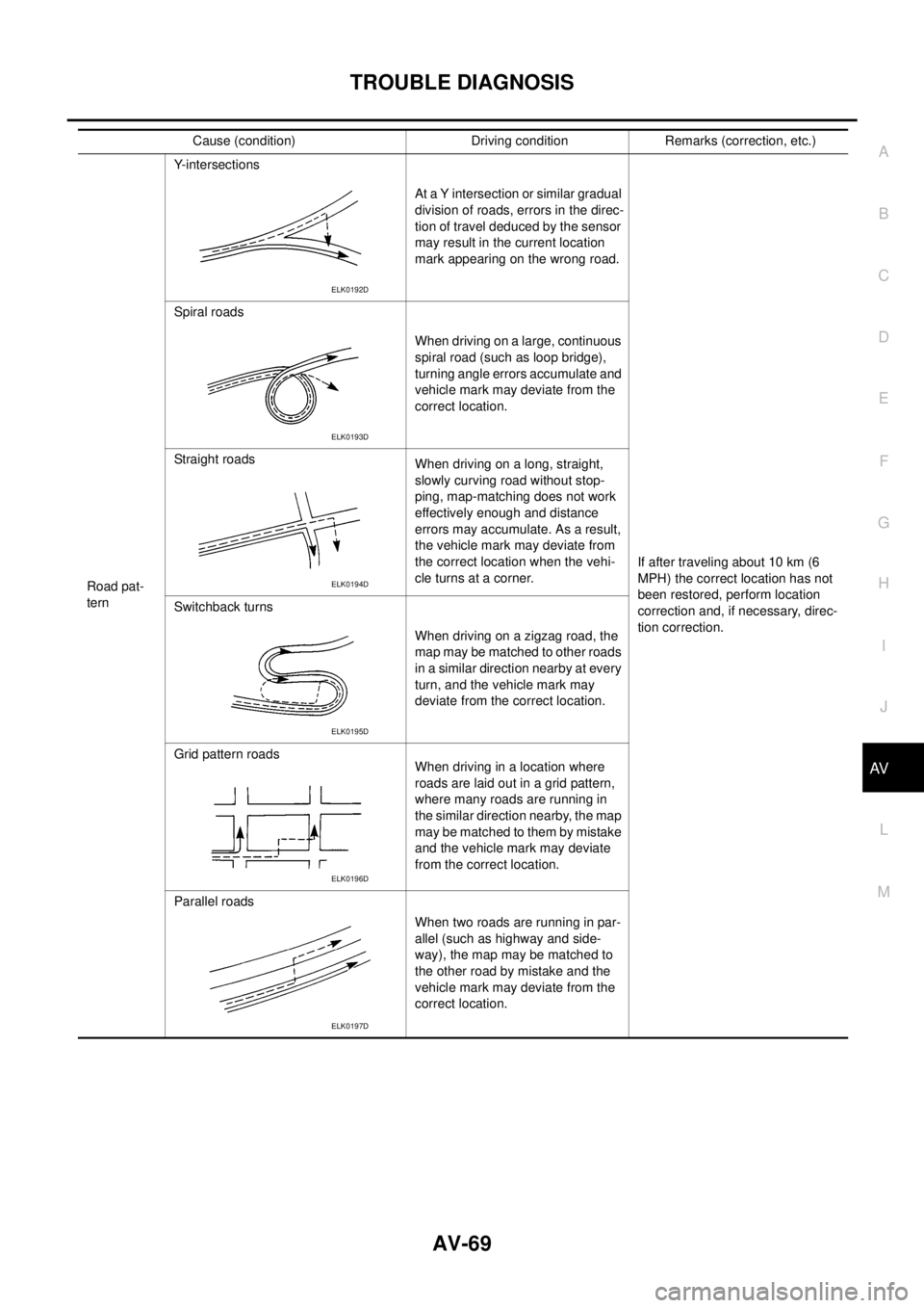
Cause (condition) Driving condition Remarks (correction, etc.)
Road pat-
ternY-intersections
At a Y intersection or similar gradual
division of roads, errors in the direc-
tion of travel deduced by the sensor
may result in the current location
mark appearing on the wrong road.
If after traveling about 10 km (6
MPH) the correct location has not
been restored, perform location
correction and, if necessary, direc-
tion correction. Spiral roads
When driving on a large, continuous
spiral road (such as loop bridge),
turning angle errors accumulate and
vehicle mark may deviate from the
correct location.
Straight roads
When driving on a long, straight,
slowly curving road without stop-
ping, map-matching does not work
effectively enough and distance
errors may accumulate. As a result,
the vehicle mark may deviate from
the correct location when the vehi-
cle turns at a corner.
Switchback turns
Whendrivingonazigzagroad,the
map may be matched to other roads
in a similar direction nearby at every
turn, and the vehicle mark may
deviate from the correct location.
Grid pattern roads
When driving in a location where
roads are laid out in a grid pattern,
where many roads are running in
the similar direction nearby, the map
may be matched to them by mistake
and the vehicle mark may deviate
from the correct location.
Parallel roads
When two roads are running in par-
allel (such as highway and side-
way), the map may be matched to
the other road by mistake and the
vehicle mark may deviate from the
correct location.
ELK0192D
ELK0193D
ELK0194D
ELK0195D
ELK0196D
ELK0197D
Page 558 of 3171

AV-70
TROUBLE DIAGNOSIS
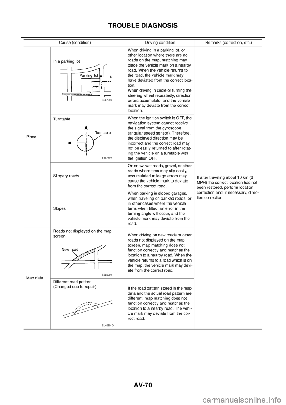
PlaceIn a parking lotWhen driving in a parking lot, or
other location where there are no
roads on the map, matching may
place the vehicle mark on a nearby
road. When the vehicle returns to
the road, the vehicle mark may
have deviated from the correct loca-
tion.
When driving in circle or turning the
steering wheel repeatedly, direction
errors accumulate, and the vehicle
mark may deviate from the correct
location.
If after traveling about 10 km (6
MPH) the correct location has not
been restored, perform location
correction and, if necessary, direc-
tion correction. TurntableWhentheignitionswitchisOFF,the
navigation system cannot receive
the signal from the gyroscope
(angular speed sensor). Therefore,
the displayed direction may be
incorrect and the correct road may
not be easily returned to after rotat-
ing the vehicle on a turntable with
the ignition OFF.
Slippery roadsOn snow, wet roads, gravel, or other
roads where tires may slip easily,
accumulated mileage errors may
cause the vehicle mark to deviate
from the correct road.
SlopesWhen parking in sloped garages,
when traveling on banked roads, or
in other cases where the vehicle
turns when tilted, an error in the
turning angle will occur, and the
vehicle mark may deviate from the
road.
Map dataRoads not displayed on the map
screenWhen driving on new roads or other
roads not displayed on the map
screen, map matching does not
function correctly and matches the
location to a nearby road. When the
vehicle returns to a road which is on
the map, the vehicle mark may devi-
ate from the correct road.
Different road pattern
(Changed due to repair)
If the road pattern stored in the map
data and the actual road pattern are
different, map matching does not
function correctly and matches the
location to a nearby road. The vehi-
cle mark may deviate from the cor-
rect road. Cause (condition) Driving condition Remarks (correction, etc.)
SEL709V
SEL710V
SEL699V
ELK0201D
Page 559 of 3171

TROUBLE DIAGNOSIS
AV-71
C
D
E
F
G
H
I
J
L
MA
B
AV
THE CURRENT POSITION MARK SHOWS A POSITION THAT IS COMPLETELY INCORRECT.
In the following cases, the current location mark may be displayed in a location that is completely incorrect. If
so, perform position/direction correction.
lWhen location correction has not been done
–If GPS satellite reception is poor and the current location mark slips out of place, it may shift to a com-
pletely unexpected location and not return unless location correction is performed. The position will be
corrected if a GPS signal can be received.
lWhen vehicle has traveled by ferry, or when vehicle has been towed.
VehicleUse of tire chains.
The vehicle mark may deviate from
the correct road.Drivethevehicleforawhile.Ifdis-
tance still deviates, adjust it with
the distance adjustment function. (If
tire chains are removed, recover
the original value.)
Use of tires other than the specified
sizeReplace all tires with the specified
size tire.
Malfunctioning air pressure of tireAdjust all tires to the specified air
pressure.
Replace tireDrive the vehicle for a while. If the
distance is still not in the correct
location, it adjusts with the distance
adjustment function.
Driving
mannerJust after the engine is startedIf vehicle is driven off just after the
engine is started when gyroscope
(angular speed sensor) correction is
not completed, the vehicle can can
be shown in the incorrect direction
and may deviate from the correct
location.Wait for a short while before driving
after starting the engine.
Continuous driving without stoppingWhen driving long distances without
stopping, direction errors may accu-
mulate, and the current location
mark may deviate from the correct
road.Stop and adjust orientation.
Abusive drivingSpinning the wheels or engaging in
other kinds of abusive driving may
result in the system being unable
perform correct detection, and may
cause the vehicle mark to deviate
from the correct road.If after traveling about 10 km (6
MPH) the correct location has not
been restored, perform location
correction and, if necessary, direc-
tion correction.
Position cor-
rection
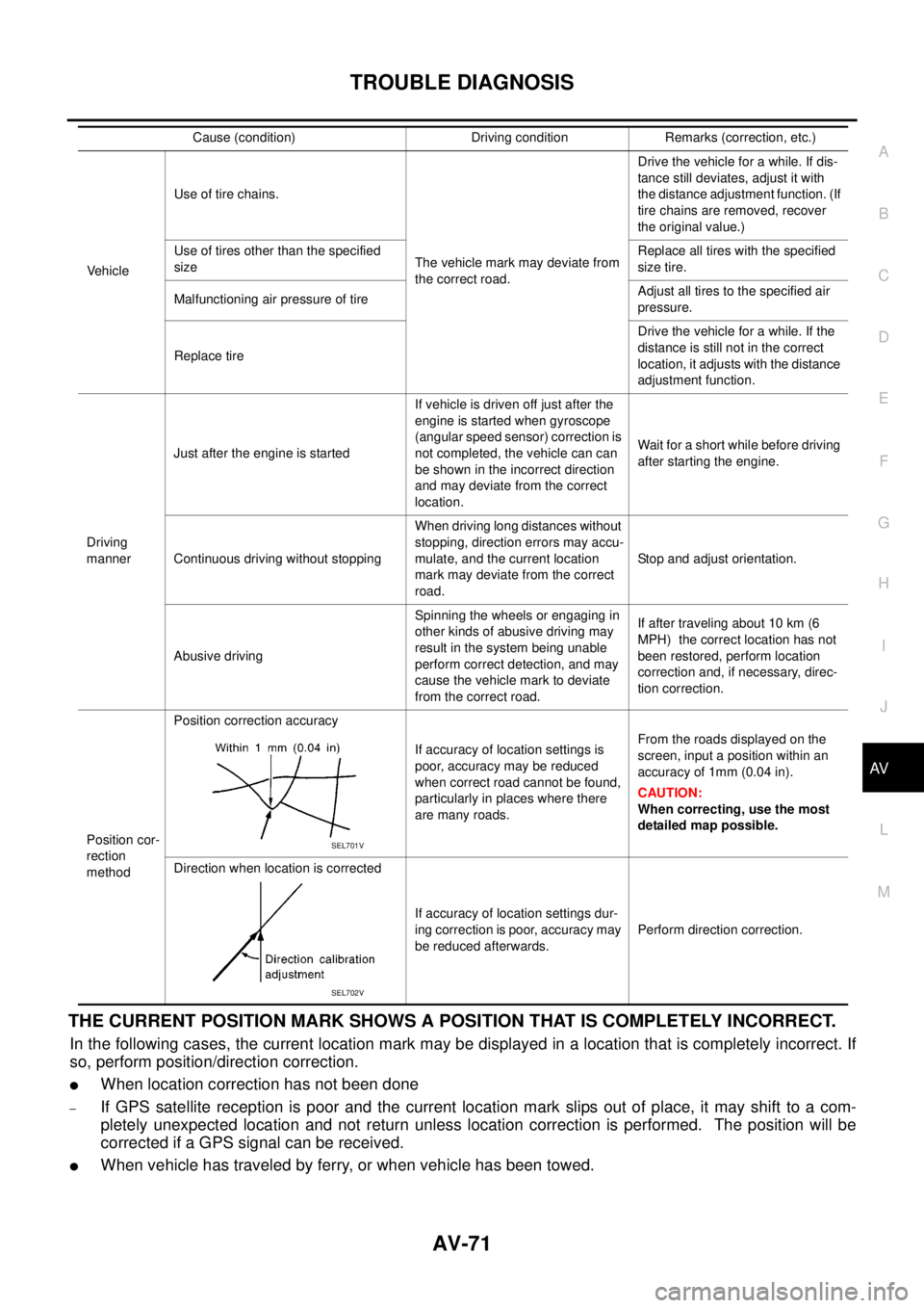
methodPosition correction accuracy
If accuracy of location settings is
poor, accuracy may be reduced
when correct road cannot be found,
particularly in places where there
are many roads.From the roads displayed on the
screen, input a position within an
accuracy of 1mm (0.04 in).
CAUTION:
When correcting, use the most
detailed map possible.
Direction when location is corrected
If accuracy of location settings dur-
ing correction is poor, accuracy may
be reduced afterwards.Perform direction correction. Cause (condition) Driving condition Remarks (correction, etc.)
SEL701V
SEL702V
Page 560 of 3171

AV-72
TROUBLE DIAGNOSIS
–Because calculation of the current location cannot be done when traveling with the ignition OFF, for exam-
ple when traveling by ferry or when being towed, the location before travel is displayed. If the precise loca-
tioncanbedetectedwithGPS,thelocationwillbecorrected.
THE CURRENT POSITION MARK JUMPS.
In the following cases, the current location mark may appear to jump as a result of automatic correction of the
current location.
lWhen map matching has been done
–If current location and the current location mark are different when map matching is done, the current
location mark may seem to jump. At this time, the location may be “corrected” to the incorrect road or to a
location which is not on a road.
lWhen GPS location correction has been done
–If current location and the current location mark are different when location is corrected using GPS mea-
surements, the current location mark may seem to jump. At this time, the location may be “corrected” to a
location which is not on a road.
THE CURRENT LOCATION MARK IS IN A RIVER OR THE SEA.
The navigation system moves the current location mark with no distinction between land and rivers or sea. If
the location mark is somehow out of place, it may appear that the vehicle is driving in a river or the sea.
CURRENT LOCATION MARK ROTATES WITHOUT OPERATION
If the ignition switch is turned ON with the turntable rotating, the rotating condition is recorded as the stop con-
dition. Therefore, the current location mark might rotate when actually stopping.
WHEN DRIVING ON THE SAME ROAD, SOMETIMES THE CURRENT LOCATION MARK IS IN
THE CORRECT PLACE AND SOMETIMES IT IS IN THE INCORRECT PLACE.
The conditions of the GPS antenna (GPS data) and gyroscope (angular speed sensor) change gradually.
Depending on the road traveled and operation of the steering wheel, the location detection results will be dif-
ferent. Therefore, even on a road on which the location has never been incorrect, conditions may cause the
vehicle mark to deviate.
LOCATION CORRECTION BY MAP MATCHING IS SLOW.
lThe map matching function needs to refer to the data of the surrounding area. It is necessary to drive
some distance for the function to work.
lBecause of the way map matching operates, when there are many roads running in similar directions in
the surrounding area a matching determination may be impossible. The location will remain uncorrected
until some special feature is found.
ALTHOUGH THE GPS RECEIVING DISPLAY IS GREEN, THE VEHICLE MARK DOES NOT
RETURN TO THE CORRECT LOCATION.
lGPS accuracy has a malfunction range of about 10 m. In some cases the current location mark may not
be on the correct street, even when GPS location correction is done.
lThe navigation system compares the results of GPS location detection with the results from map-match-
ing location detection. The one that is determined to have higher accuracy is used.
lPosition correction by GPS is not available while the vehicle is stopped.
THE NAME OF THE CURRENT PLACE IS NOT DISPLAYED.
The current place name might not be displayed when there is no name of place information in the map screen.
THE DISPLAY IS DIFFERENT BETWEEN BIRDVIEW®AND (FLAT) MAP DISPLAY.
The following is different at birdview®.
lThe current place name displays names that are primarily in the direction of vehicle travel.
lThe amount of time before the vehicle travel or turn angle is updated on the screen is longer than for the
(flat) map display.
lThe conditions for display of place names, roads, and other data are different for nearby areas and for
more distant areas.
lSome trimming of the character data is done to prevent the display from becoming too complex. In some
cases and in some locations, the display contents may differ.
lThe same place name, street name, etc. may be displayed multiple times.
Page 575 of 3171

BCM (BODY CONTROL MODULE)
BCS-9
C
D
E
F
G
H
I
J
L
MA
B
BCS
MAJOR COMPONENTS AND CONTROL SYSTEM
CAN Communication System DescriptionEKS00PA2
Refer toLAN-23, "CAN COMMUNICATION".
System Input Output
Remote keyless entry system Keyfob
lAll-door locking actuator
lTurn signal lamp (LH, RH)
lCombination meter (Turn signal
lamp)
Power door lock system Door lock/unlock switch All-door locking actuator
Power supply (IGN) to power win-
dow and sunroofIgnition power supply Power window and sunroof system
Power supply (BAT) to power
window and sunroofBattery power supply Power window and sunroof system
Headlamp Combination switch IPDM E/R
Tail lamp Combination switch IPDM E/R
Front fog lamp Combination switch IPDM E/R
Rear fog lamp Combination switch
lRear fog lamp
lCombination meter
Turn signal lamp Combination switch
lTurn signal lamp
lCombination meter
Hazard lamp Hazard switch
lTurn signal lamp
lCombination meter
Room lamp timer
lKey switch
lKeyfob
lDoor lock/unlock switch
lFront door switch driver side
lAll-door switchInterior room lamp
Light warning chime
lCombination switch
lKey switch
lFront door switch driver sideCombination meter (warning buzzer)
Rain-sensing intermittent wiper
lCombination switch
lLight and rain sensorIPDM E/R
Vehicle-speed-sensing intermit-
tent wiper
lCombination switch
lCombination meterIPDM E/R
Headlamp washer Combination switch IPDM E/R
Rear window defogger
lRear window defogger switch
lIgnition switch (ACC, ON)IPDM E/R
A/C switch signal Front air control ECM
Blower fan switch signal Front air control ECM
Page 602 of 3171

BL-18
RADIATOR CORE SUPPORT
RADIATOR CORE SUPPORT
PFP:62500
Removal and InstallationEIS00DGJ
REMOVAL
1. Remove the hood assembly. Refer toBL-14, "Removal and Installation of Hood Assembly".
2. Remove the front grille. Refer toEI-19, "
FRONT GRILLE".
3. Remove the front bumper, bumper reinforcement and bumper bracket. Refer toEI-15, "
FRONT BUMPER"
.
4. Remove the headlamp assembly (LH/RH). Refer toLT-30, "
Removal and Installation".
5. Remove the air intake duct (Air guide). Refer toEM-15, "
AIR CLEANER AND AIR DUCT".
6. Remove the charge air cooler. (for YD25 engine models only) Refer toEM-18, "
CHARGE AIR COOLER".
7. Remove the power steering oil cooler. Refer toPS-30, "
HYDRAULIC LINE".
8. Remove the A/T fluid cooler and A/T fluid cooler tube mounting nuts. Refer toAT- 2 4 4 , "
A/T FLUID
COOLER".
9. Remove the hood lock assembly, and then remove the hood lock cable. Refer toBL-15, "
Removal and
Installation of Hood Lock Control".
10. Remove the horn harness connector.
11. Disconnect the ambient sensor connector and remove the ambient sensor. Refer toAT C - 11 7 , "
Removal
and Installation".
12. Remove the mounting harness clip on radiator core support assembly, the harness is separate.
13. Remove the upper radiator bracket. Refer toCO-11, "
RADIATOR".
1. Radiator core support assembly 2. Air intake duct (Air guide) RH 3. Air intake duct (Air guide) LH
4. Horn (Low) 5. Headlamp lower bracket RH 6. Headlamp lower bracket LH
7. Headlamp side bracket RH 8. Headlamp side bracket LH
MIIB0979E
Page 801 of 3171

LOAD SENSING VALVE
BR-15
C
D
E
G
H
I
J
K
L
MA
B
BR
LOAD SENSING VALVEPFP:46400
Removal and InstallationEFS006A7
CAUTION:
lAlways use a flare nut wrench to remove brake tube. Be careful not to damage flare nut and brake
tube. Also, use flare nut torque wrench for brake tube installation and tightening to the specified
torque. Refer toBR-12, "
Hydraulic Circuit".
lRefill with new brake fluid “DOT 3” or “DOT 4”.
lNever reuse drained brake fluid.
REMOVAL
1. Drain brake fluid.
2. Cover brake line connections/openings to protect them from foreign material such as dust or dirt.
3. Using a flare nut wrench, remove flare nut on brake tube from load sensing valve.
4. Remove mounting bolts to remove load sensing valve.
INSTALLATION
lCarefully performing the following, install in the reverse order of removal.
lAfter installing load sensing valve to vehicle, perform the following: bleed air from brake line. Refer toBR-
11 , "Bleeding Brake System", and check mounting length “L” of sensor spring.
1. Torsion member 2. Load sensing valve bracket 3. Load sensing valve
4. Stopper 5. Sensor spring 6. Rear axle tube
Refer to GI section for symbol marks in the figure.
SFIA3190E
Page 802 of 3171

BR-16
LOAD SENSING VALVE
Inspection
EFS006A8
INSPECTION
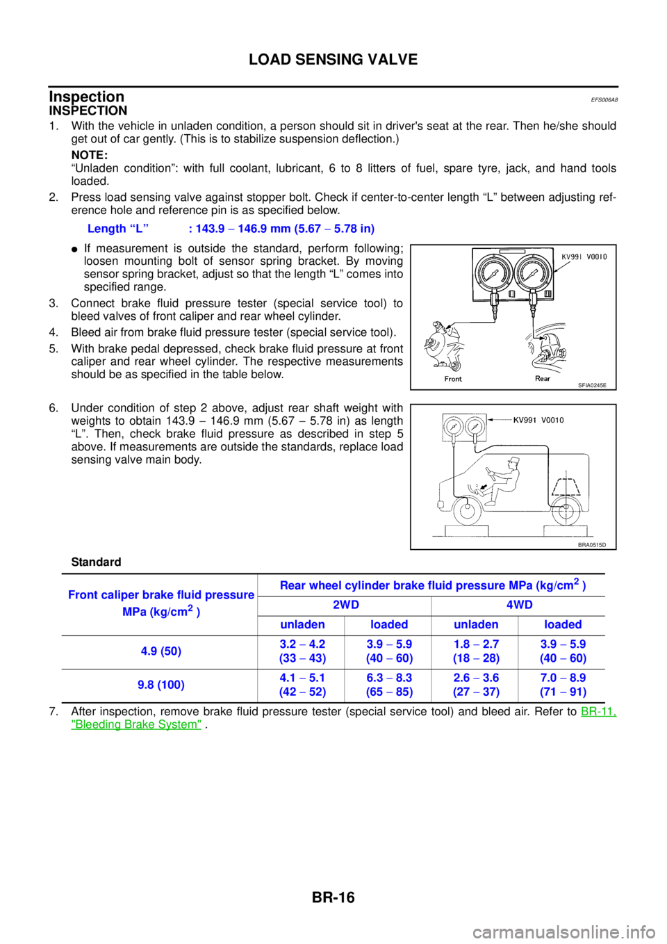
1. With the vehicle in unladen condition, a person should sit in driver's seat at the rear. Then he/she should
get out of car gently. (This is to stabilize suspension deflection.)
NOTE:
“Unladen condition”: with full coolant, lubricant, 6 to 8 litters of fuel, spare tyre, jack, and hand tools
loaded.
2. Press load sensing valve against stopper bolt. Check if center-to-center length “L” between adjusting ref-
erence hole and reference pin is as specified below.
lIf measurement is outside the standard, perform following;
loosen mounting bolt of sensor spring bracket. By moving
sensor spring bracket, adjust so that the length “L” comes into
specified range.
3. Connect brake fluid pressure tester (special service tool) to
bleed valves of front caliper and rear wheel cylinder.
4. Bleed air from brake fluid pressure tester (special service tool).
5. With brake pedal depressed, check brake fluid pressure at front
caliper and rear wheel cylinder. The respective measurements
should be as specified in the table below.
6. Under condition of step 2 above, adjust rear shaft weight with
weights to obtain 143.9-146.9 mm (5.67-5.78 in) as length
“L”. Then, check brake fluid pressure as described in step 5
above. If measurements are outside the standards, replace load
sensing valve main body.
Standard
7. After inspection, remove brake fluid pressure tester (special service tool) and bleed air. Refer toBR-11,
"Bleeding Brake System". Length “L” : 143.9-146.9 mm (5.67-5.78 in)
SFIA0245E
BRA0515D
Front caliper brake fluid pressure
MPa (kg/cm
2)Rear wheel cylinder brake fluid pressure MPa (kg/cm
2)
2WD 4WD
unladen loaded unladen loaded
4.9 (50)3.2-4.2
(33-43)3.9-5.9
(40-60)1.8-2.7
(18-28)3.9-5.9
(40-60)
9.8 (100)4.1-5.1
(42-52)6.3-8.3
(65-85)2.6-3.6
(27-37)7.0-8.9
(71-91)