2005 NISSAN NAVARA sensor
[x] Cancel search: sensorPage 907 of 3171
THERMOSTAT AND WATER PIPING
CO-23
C
D
E
F
G
H
I
J
K
L
MA
CO
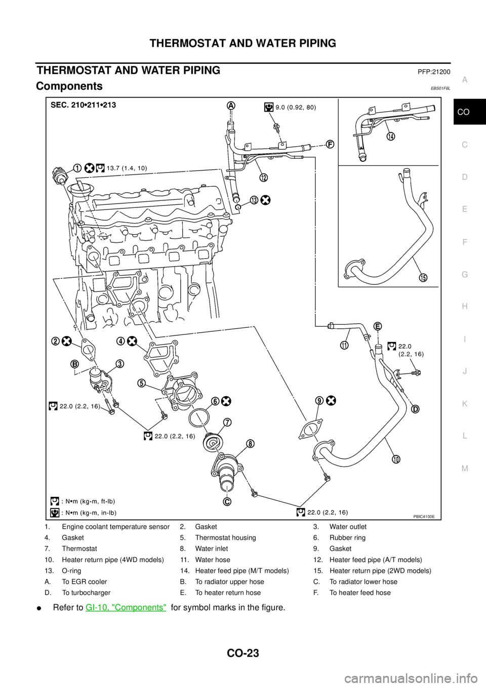
THERMOSTAT AND WATER PIPINGPFP:21200
ComponentsEBS01F6L
lRefer toGI-10, "Components"for symbol marks in the figure.
1. Engine coolant temperature sensor 2. Gasket 3. Water outlet
4. Gasket 5. Thermostat housing 6. Rubber ring
7. Thermostat 8. Water inlet 9. Gasket
10. Heater return pipe (4WD models) 11. Water hose 12. Heater feed pipe (A/T models)
13. O-ring 14. Heater feed pipe (M/T models) 15. Heater return pipe (2WD models)
A. To EGR cooler B. To radiator upper hose C. To radiator lower hose
D. To turbocharger E. To heater return hose F. To heater feed hose
PBIC4100E
Page 911 of 3171

DI-1
DRIVER INFORMATION SYSTEM
K ELECTRICAL
CONTENTS
C
D
E
F
G
H
I
J
L
M
SECTIONDI
A
B
DI
DRIVER INFORMATION SYSTEM
PRECAUTION ............................................................ 3
Precautions for Supplemental Restraint System
(SRS)“AIRBAG”and“SEATBELTPRE-TEN-
SIONER” .................................................................. 3
Wiring Diagrams and Trouble Diagnosis .................. 3
COMBINATION METERS ........................................... 4
System Description .................................................. 4
UNIFIED METER CONTROL UNIT ...................... 4
POWER SUPPLY AND GROUND CIRCUIT ........ 4
SPEEDOMETER ................................................... 4
TACHOMETER ..................................................... 4
WATER TEMPERATURE GAUGE ........................ 4
FUEL GAUGE ....................................................... 5
ODO/TRIP METER ............................................... 5
TRIP COMPUTER ................................................ 5
ENGINE OIL MAINTENANCE INFORMATION..... 6
METER ILLUMINATION CONTROL ..................... 6
CLOCK .................................................................. 6
AMBIENT AIR TEMPERATURE INDICATION ...... 6
Component Parts and Harness Connector Location..... 7
Arrangement of Combination Meter ......................... 8
Internal Circuit .......................................................... 9
Wiring Diagram — METER — ................................ 10
Terminals and Reference Value for Combination
Meter ...................................................................... 12
Self-Diagnosis Mode of Combination Meter ........... 13
FUNCTION .......................................................... 13
OPERATION PROCEDURE ............................... 13
TEST ITEM ......................................................... 13
CONSULT-II Function (METER) ............................. 15
CONSULT-II BASIC OPERATION ....................... 15
SELF-DIAG RESULTS ........................................ 16
DATA MONITOR ................................................. 17
Trouble Diagnosis .................................................. 18
HOW TO PERFORM TROUBLE DIAGNOSIS ... 18
PRELIMINARY CHECK ...................................... 19
Symptom Chart ...................................................... 19
Power Supply and Ground Circuit Inspection ........ 19
Vehicle Speed Signal Inspection ............................ 20
Engine Speed Signal Inspection ............................ 21Engine Coolant Temperature Signal Inspection ..... 21
Fuel Level Sensor Signal Inspection ...................... 22
Ambient Sensor Signal Inspection .......................... 24
Fuel Gauge Fluctuates, Indicates Wrong Value, or
Varies ...................................................................... 25
Fuel Gauge Does Not Move to Full position ........... 25
DTC [U1000] CAN Communication Circuit ............. 26
DTC [B2205] Vehicle Speed Circuit ........................ 26
Electrical Components Inspection .......................... 27
FUEL LEVEL SENSOR UNIT CHECK ................ 27
AMBIENT SENSOR CHECK ............................... 27
Removal and Installation of Combination Meter ..... 27
WARNING LAMPS .................................................... 28
System Description ................................................. 28
OIL PRESSURE WARNING LAMP ..................... 28
Component Parts and Harness Connector Location... 28
Schematic ............................................................... 29
Wiring Diagram — WARN — .................................. 30
A/T MODELS ....................................................... 30
M/T MODELS ...................................................... 37
Oil Pressure Warning Lamp Stays Off (Ignition
Switch ON) ............................................................. 44
Oil Pressure Warning Lamp Does Not Turn Off (Oil
Pressure Is Normal) ................................................ 45
Oil Pressure Warning Lamp Keeps Blinking (Oil
Level Is Normal) ..................................................... 46
Component Inspection ............................................ 47
OIL PRESSURE SWITCH ................................... 47
OIL LEVEL SENSOR .......................................... 47
A/T INDICATOR ........................................................ 48
System Description ................................................. 48
Wiring Diagram — AT/IND — ................................. 49
A/T Indicator Does Not Illuminate ........................... 50
WARNING CHIME ..................................................... 51
System Description ................................................. 51
POWER SUPPLY AND GROUND CIRCUIT ....... 51
LIGHT WARNING CHIME ................................... 51
KEY REMINDER WARNING CHIME .................. 51
LOW-FUEL WARNING CHIME ........................... 51
SEAT BELT WARNING CHIME ........................... 52
Page 914 of 3171

DI-4
COMBINATION METERS
COMBINATION METERS
PFP:24814
System DescriptionEKS00L8E
UNIFIED METER CONTROL UNIT
lSpeedometer, odo/trip meter, tachometer, fuel gauge and water temperature gauge are controlled by the
unified meter control unit, which is built into the combination meter.
lWarning lamp and indicator lamp are controlled by signals drawn from each unit with CAN communication
and components connected directly to the combination meter.
lOdo/trip meter display is included in the combination meter, which displays odometer, trip-meter, vehicle
information (trip computer, engine oil maintenance information)
*and A/T position*.
*: Vehicles with each system only.
lClock display is included in the combination meter, which displays current time, ambient air temperature*
and 4WD indicator*.
*: Vehicles with each system only.
lUnified meter control unit corresponds a CONSULT-II function (self-diagnosis results and data monitor).
lThe following items can be checked during self-diagnosis mode.
–Sweep of gauges pointer
–Present gauge values
–Odo/trip meter display and clock display segments
–Condition of warning lamps/indicator lamps controlled by unified meter control unit
–Battery voltage
–Driver's seat belt buckle switch status
–CPU status of unified meter control unit
POWER SUPPLY AND GROUND CIRCUIT
Power is supplied at all times
lthrough 10A fuse [No.19, located in the fuse block (J/B)]
lto combination meter terminal 3.
With the ignition switch in the ON or START position, power is supplied
lthrough 10A fuse [No.14, located in the fuse block (J/B)]
lto combination meter terminal 16.
Ground is supplied
lto combination meter terminals 13 and 23
lthrough grounds M21, M80 and M83.
SPEEDOMETER
The speedometer indicates the vehicle speed.
lABS actuator and electric unit (control unit) converses a pulse signal from wheel sensor to vehicle speed
signal, and transmits vehicle speed signal to combination meter with CAN communication.
lCombination meter converses the vehicle speed signal to angle signal, and commands to speedometer.
TACHOMETER
The tachometer indicates engine speed in revolutions per minute (rpm).
lECM converses a signal from crank position sensor to engine speed signal, and transmits to combination
meter with CAN communication.
lCombination meter converses the engine speed signal to angle signal, and commands to tachometer.
WATER TEMPERATURE GAUGE
The water temperature gauge indicates the engine coolant temperature.
lECM converses a signal from water temperature sensor to engine coolant temperature signal, and trans-
mits to combination meter with CAN communication.
lCombination meter converses the engine coolant temperature signal to angle signal, and commands to
water temperature gauge.
Page 915 of 3171
COMBINATION METERS
DI-5
C
D
E
F
G
H
I
J
L
MA
B
DI
FUEL GAUGE
The fuel gauge indicates the approximate fuel level in the fuel tank.
Combination meter reads a resistor signal from fuel level sensor unit.
Signal is supplied
lto combination meter terminal 9
lthrough fuel level sensor unit terminal 1 and 2
lfrom combination meter terminal 4.
ODO/TRIP METER
lABS actuator and electric unit (control unit) converses a pulse signal from wheel sensor to vehicle speed
signal, and transmits vehicle speed signal to combination meter with CAN communication.
lCombination meter uses the vehicle speed signal to calculate the mileage, and it displays.
How to Change/ Reset Indication
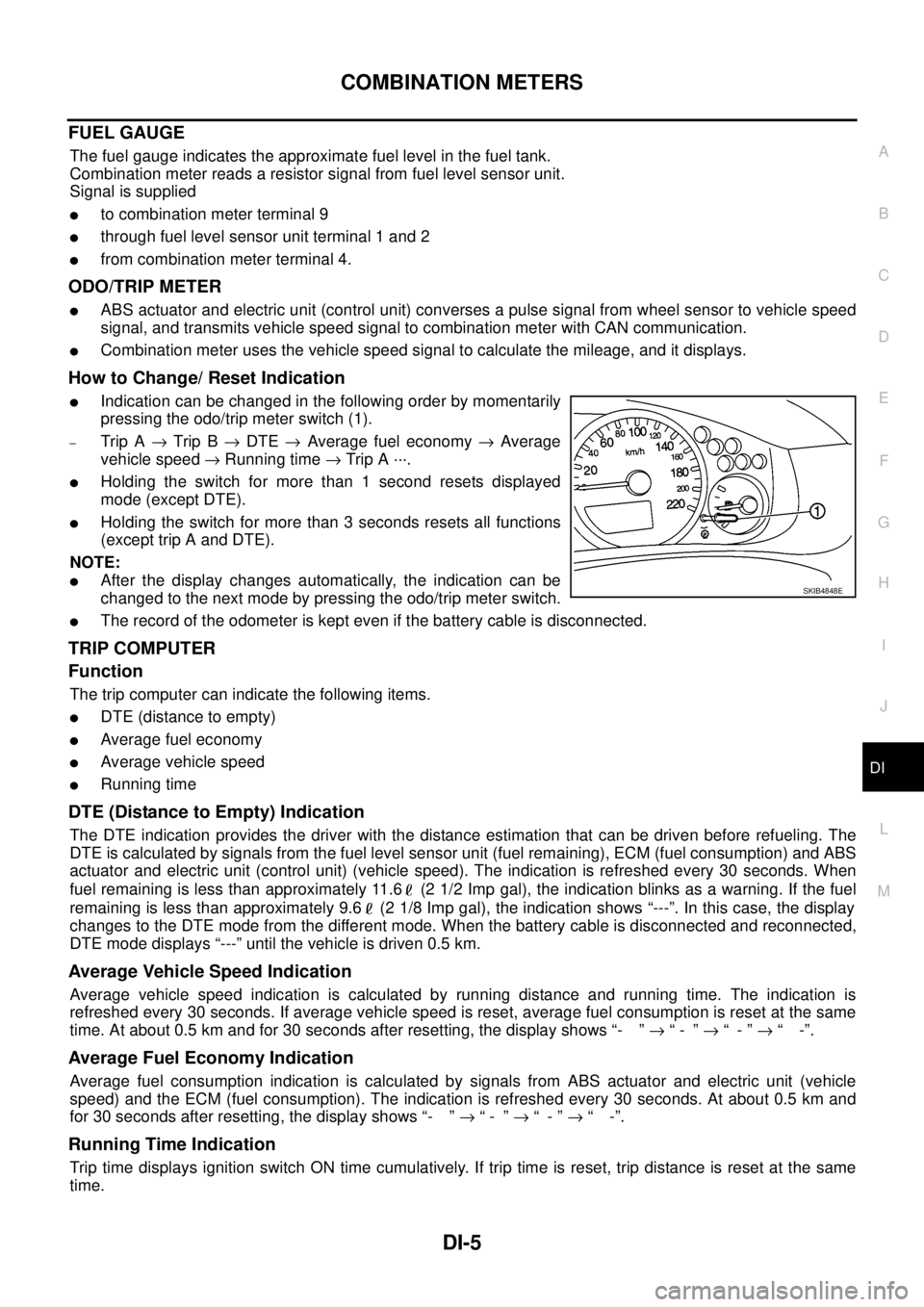
lIndication can be changed in the following order by momentarily
pressing the odo/trip meter switch (1).
–Trip A®Trip B®DTE®Average fuel economy®Average
vehicle speed®Running time®Trip A ···.
lHolding the switch for more than 1 second resets displayed
mode (except DTE).
lHolding the switch for more than 3 seconds resets all functions
(except trip A and DTE).
NOTE:
lAfter the display changes automatically, the indication can be
changed to the next mode by pressing the odo/trip meter switch.
lThe record of the odometer is kept even if the battery cable is disconnected.
TRIP COMPUTER
Function
The trip computer can indicate the following items.
lDTE (distance to empty)
lAverage fuel economy
lAverage vehicle speed
lRunning time
DTE (Distance to Empty) Indication
The DTE indication provides the driver with the distance estimation that can be driven before refueling. The
DTE is calculated by signals from the fuel level sensor unit (fuel remaining), ECM (fuel consumption) and ABS
actuator and electric unit (control unit) (vehicle speed). The indication is refreshed every 30 seconds. When
fuel remaining is less than approximately 11.6 (2 1/2 Imp gal), the indication blinks as a warning. If the fuel
remaining is less than approximately 9.6 (2 1/8 Imp gal), the indication shows “---”. In this case, the display
changes to the DTE mode from the different mode. When the battery cable is disconnected and reconnected,
DTE mode displays “---” until the vehicle is driven 0.5 km.
Average Vehicle Speed Indication
Average vehicle speed indication is calculated by running distance and running time. The indication is
refreshed every 30 seconds. If average vehicle speed is reset, average fuel consumption is reset at the same
time. At about 0.5 km and for 30 seconds after resetting, the display shows “- ”®“- ”®“-”®“ -”.
Average Fuel Economy Indication
Average fuel consumption indication is calculated by signals from ABS actuator and electric unit (vehicle
speed) and the ECM (fuel consumption). The indication is refreshed every 30 seconds. At about 0.5 km and
for 30 seconds after resetting, the display shows “- ”®“- ”®“-”®“ -”.
Running Time Indication
Trip time displays ignition switch ON time cumulatively. If trip time is reset, trip distance is reset at the same
time.
SKIB4848E
Page 916 of 3171

DI-6
COMBINATION METERS
ENGINE OIL MAINTENANCE INFORMATION
lEngine oil maintenance information displays maintenance intervals of engine oil.
lWith ignition switch ON position, engine oil maintenance information is displayed on odo/trip meter display
for 5 seconds.
NOTE:
Refer to Owner's Manual for setting.
METER ILLUMINATION CONTROL
When the lighting switch is turned ON, the odo/trip meter switch (1)
can be used to adjust the brightness of the combination meter illumi-
nation.
CLOCK
With ignition switch ON position, combination meter displays clock
on clock display. Time can be adjusted by clock switch (1). Clock can
be adjusted to 12-hour or 24-hour cycle clock.
NOTE:
If the battery cable is disconnected, the clock displays the time 12:00
in 12-hour mode.
AMBIENT AIR TEMPERATURE INDICATION
Combination meter displays ambient air temperature on clock display.
With ignition switch ON, “°C” blinks for a while. Ambient air temperature indication can be selected between
Centigrade and Fahrenheit.
Combination meter reads ambient air temperature signal from ambient sensor.
Signal is supplied
lfrom combination meter terminal 49
lthrough ambient sensor terminals 1 and 2
lto combination meter terminal 50.
When a temperature detected by sensor rises, combination meter controls increase of the indicated tempera-
ture depending on engine heat and other effective factors.
lIf the vehicle speed is more than 20 km/h, the indicated temperature rises according to the vehicle speed.
lIf the vehicle speed is less than 20 km/h, the indicated temperature is maintained.
When a temperature detected by sensor falls, the temperature is indicated immediately.
NOTE:
The range indicated on the display is between-30 and 60°C for Centigrade or between-22 and 99°Ffor
Fahrenheit.
lWhen the temperature is from-40°C(-40°F) to-30°C(-22°F), “--°C” is indicated on the display as
over range.
lWhen the temperature is under-40°C(-40°F) or over 60°C(140°F), nothing is indicated.
lWhen indicated temperature becomes less than 3°C(37°F), ambient air temperature indication blinks
warning. After blinking for 20 seconds, only “°C” blinks. At more than 4°C(39°F) the display stops blink-
ing.
SKIB4848E
PKIC1129E
Page 922 of 3171
DI-12
COMBINATION METERS
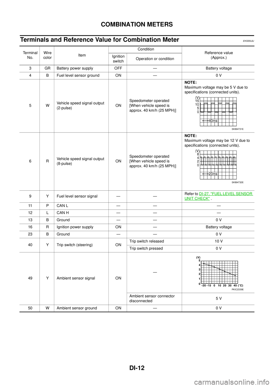
Terminals and Reference Value for Combination Meter
EKS00L8J
Te r m i n a l
No.Wire
colorItemCondition
Reference value
(Approx.) Ignition
switchOperation or condition
3 GR Battery power supply OFF — Battery voltage
4 B Fuel level sensor ground ON — 0 V
5WVehicle speed signal output
(2-pulse)ONSpeedometer operated
[When vehicle speed is
approx. 40 km/h (25 MPH)]NOTE:
Maximum voltage may be 5 V due to
specifications (connected units).
6RVehicle speed signal output
(8-pulse)ONSpeedometer operated
[When vehicle speed is
approx. 40 km/h (25 MPH)]NOTE:
Maximum voltage may be 12 V due to
specifications (connected units).
9 Y Fuel level sensor signal — —Refer toDI-27, "
FUEL LEVEL SENSOR
UNIT CHECK".
11 P C A N L — — —
12 L CAN H — — —
13 B Ground — — 0 V
16 R Ignition power supply ON — Battery voltage
23 B Ground — — 0 V
40 Y Trip switch (steering) ONTrip switch released 10 V
Trip switch pressed 0 V
49 Y Ambient sensor signal ON—
Ambient sensor connector
disconnected5V
50 W Ambient sensor ground ON — 0 V
SKIB4731E
SKIB4732E
PKIC2339E
Page 924 of 3171
DI-14
COMBINATION METERS
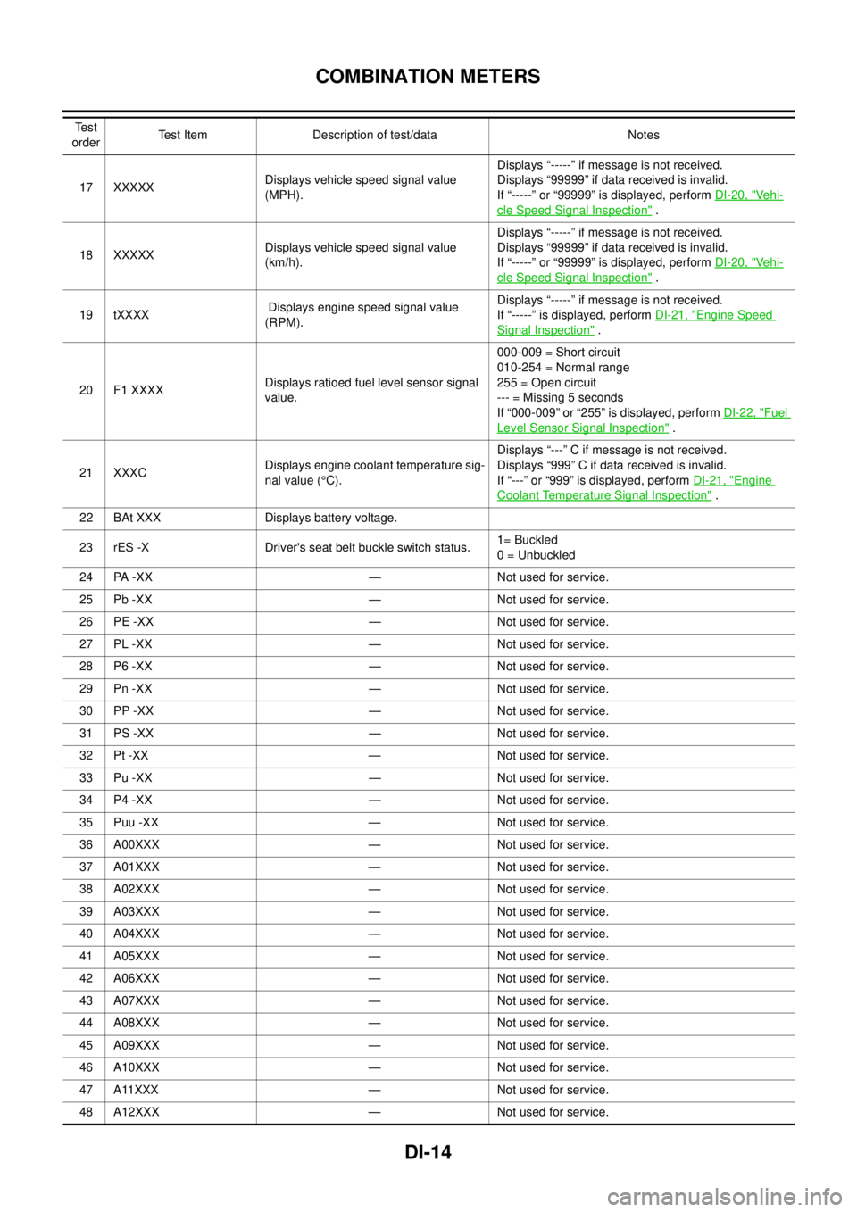
17 XXXXXDisplays vehicle speed signal value
(MPH).Displays “-----” if message is not received.
Displays “99999” if data received is invalid.
If “-----” or “99999” is displayed, performDI-20, "Ve h i-
cle Speed Signal Inspection".
18 XXXXXDisplays vehicle speed signal value
(km/h).Displays “-----” if message is not received.
Displays “99999” if data received is invalid.
If “-----” or “99999” is displayed, performDI-20, "
Ve h i-
cle Speed Signal Inspection".
19 tXXXXDisplays engine speed signal value
(RPM).Displays “-----” if message is not received.
If “-----” is displayed, performDI-21, "
Engine Speed
Signal Inspection".
20 F1 XXXXDisplays ratioed fuel level sensor signal
value.000-009 = Short circuit
010-254 = Normal range
255 = Open circuit
--- = Missing 5 seconds
If “000-009” or “255” is displayed, performDI-22, "
Fuel
Level Sensor Signal Inspection".
21 XXXCDisplays engine coolant temperature sig-
nal value (°C).Displays “---” C if message is not received.
Displays “999” C if data received is invalid.
If “---” or “999” is displayed, performDI-21, "
Engine
Coolant Temperature Signal Inspection".
22 BAt XXX Displays battery voltage.
23 rES -X Driver's seat belt buckle switch status.1= Buckled
0 = Unbuckled
24 PA -XX — Not used for service.
25 Pb -XX — Not used for service.
26 PE -XX — Not used for service.
27 PL -XX — Not used for service.
28 P6 -XX — Not used for service.
29 Pn -XX — Not used for service.
30 PP -XX — Not used for service.
31 PS -XX — Not used for service.
32 Pt -XX — Not used for service.
33 Pu -XX — Not used for service.
34 P4 -XX — Not used for service.
35 Puu -XX — Not used for service.
36 A00XXX — Not used for service.
37 A01XXX — Not used for service.
38 A02XXX — Not used for service.
39 A03XXX — Not used for service.
40 A04XXX — Not used for service.
41 A05XXX — Not used for service.
42 A06XXX — Not used for service.
43 A07XXX — Not used for service.
44 A08XXX — Not used for service.
45 A09XXX — Not used for service.
46 A10XXX — Not used for service.
47 A11XXX — Not used for service.
48 A12XXX — Not used for service. Te s t
orderTest Item Description of test/data Notes
Page 929 of 3171
COMBINATION METERS
DI-19
C
D
E
F
G
H
I
J
L
MA
B
DI
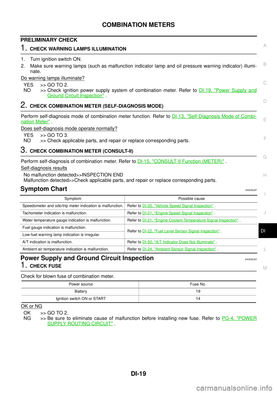
PRELIMINARY CHECK
1.CHECK WARNING LAMPS ILLUMINATION
1. Turn ignition switch ON.
2. Make sure warning lamps (such as malfunction indicator lamp and oil pressure warning indicator) illumi-
nate.
Do warning lamps illuminate?
YES >> GO TO 2.
NO >> Check ignition power supply system of combination meter. Refer toDI-19, "
Power Supply and
Ground Circuit Inspection".
2.CHECK COMBINATION METER (SELF-DIAGNOSIS MODE)
Perform self-diagnosis mode of combination meter function. Refer toDI-13, "
Self-Diagnosis Mode of Combi-
nation Meter".
Does self-diagnosis mode operate normally?
YES >> GO TO 3.
NO >> Check applicable parts, and repair or replace corresponding parts.
3.CHECK COMBINATION METER (CONSULT-II)
Perform self-diagnosis of combination meter. Refer toDI-15, "
CONSULT-II Function (METER)".
Self-diagnosis results
No malfunction detected>>INSPECTION END
Malfunction detected>>Check applicable parts, and repair or replace corresponding parts.
Symptom ChartEKS00L8P
Power Supply and Ground Circuit InspectionEKS00L8O
1.CHECK FUSE
Check for blown fuse of combination meter.
OK or NG
OK >> GO TO 2.
NG >> Be sure to eliminate cause of malfunction before installing new fuse. Refer toPG-4, "
POWER
SUPPLY ROUTING CIRCUIT".
Symptom Possible cause
Speedometer and odo/trip meter indication is malfunction. Refer toDI-20, "
Vehicle Speed Signal Inspection".
Tachometer indication is malfunction. Refer toDI-21, "
Engine Speed Signal Inspection".
Water temperature gauge indication is malfunction. Refer toDI-21, "
Engine Coolant Temperature Signal Inspection".
Fuel gauge indication is malfunction.
Refer toDI-22, "
Fuel Level Sensor Signal Inspection".
Low-fuel warning lamp indication is irregular.
A/T indication is malfunction. Refer toDI-50, "
A/T Indicator Does Not Illuminate".
Ambient air temperature indication is malfunction. Refer toDI-24, "
Ambient Sensor Signal Inspection".
Power source Fuse No.
Battery 19
Ignition switch ON or START 14