2005 NISSAN NAVARA sensor
[x] Cancel search: sensorPage 475 of 3171
REFRIGERANT LINES
ATC-141
C
D
E
F
G
H
I
K
L
MA
B
AT C
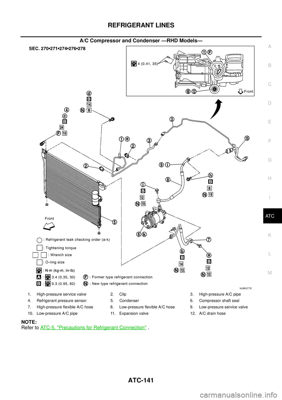
A/C Compressor and Condenser —RHD Models—
NOTE:
Refer toAT C - 5 , "
Precautions for Refrigerant Connection".
MJIB0277E
1. High-pressure service valve 2. Clip 3. High-pressure A/C pipe
4. Refrigerant pressure sensor 5. Condenser 6. Compressor shaft seal
7. High-pressure flexible A/C hose 8. Low-pressure flexible A/C hose 9. Low-pressure service valve
10. Low-pressure A/C pipe 11. Expansion valve 12. A/C drain hose
Page 481 of 3171
REFRIGERANT LINES
ATC-147
C
D
E
F
G
H
I
K
L
MA
B
AT C
CAUTION:
lReplace the O-ring of the low-pressure flexible A/C hose with a new one, then apply compressor
oil to it for installation.
lAfter charging refrigerant, check for leaks.
Removal and Installation for Low-pressure A/C PipeEJS006CS
REMOVAL
1. Discharge the refrigerant. Refer toATC-138, "HFC-134a (R-134a) Service Procedure".
2. Disconnect the heater pump connector.
3. Remove the heater pump from the bracket and reposition out of the way. Do not disconnect the heater
hoses from the heater pump.
4. Remove the low-pressure A/C pipe. Refer toATC-140, "
Components".
CAUTION:
Cap or wrap the joint of the pipe with suitable material such as vinyl tape to avoid the entry of air.
INSTALLATION
Installation is in the reverse order of removal.
Refer toATC-140, "
Components".
CAUTION:
lReplace the O-ring of the low-pressure A/C pipe with a new one, then apply compressor oil to it for
installation.
lAfter charging refrigerant, check for leaks.
Removal and Installation for Refrigerant Pressure SensorEJS006CV
REMOVAL
1. Discharge the refrigerant. Refer toATC-138, "HFC-134a (R-134a) Service Procedure".
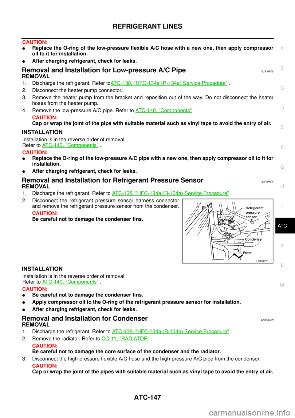
2. Disconnect the refrigerant pressure sensor harness connector
and remove the refrigerant pressure sensor from the condenser.
CAUTION:
Be careful not to damage the condenser fins.
INSTALLATION
Installation is in the reverse order of removal.
Refer toATC-140, "
Components".
CAUTION:
lBe careful not to damage the condenser fins.
lApply compressor oil to the O-ring of the refrigerant pressure sensor for installation.
lAfter charging refrigerant, check for leaks.
Removal and Installation for CondenserEJS006CW
REMOVAL
1. Discharge the refrigerant. Refer toATC-138, "HFC-134a (R-134a) Service Procedure".
2. Remove the radiator. Refer toCO-11, "
RADIATOR".
CAUTION:
Be careful not to damage the core surface of the condenser and the radiator.
3. Disconnect the high-pressure flexible A/C hose and the high-pressure A/C pipe from the condenser.
CAUTION:
Cap or wrap the joint of the pipes with suitable material such as vinyl tape to avoid the entry of air.
LJIA0177E
Page 482 of 3171
ATC-148
REFRIGERANT LINES
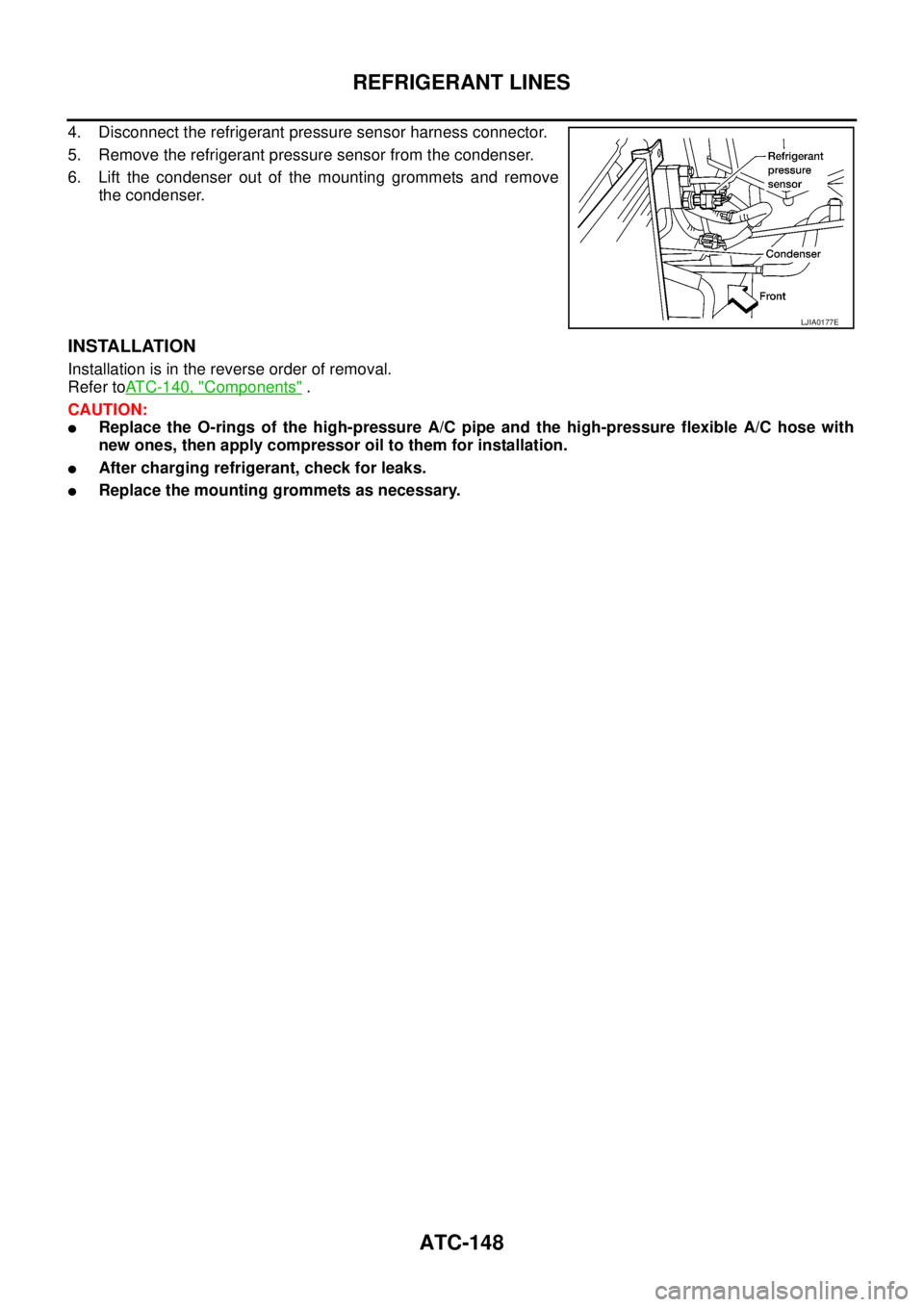
4. Disconnect the refrigerant pressure sensor harness connector.
5. Remove the refrigerant pressure sensor from the condenser.
6. Lift the condenser out of the mounting grommets and remove
the condenser.
INSTALLATION
Installation is in the reverse order of removal.
Refer toATC-140, "
Components".
CAUTION:
lReplace the O-rings of the high-pressure A/C pipe and the high-pressure flexible A/C hose with
new ones, then apply compressor oil to them for installation.
lAfter charging refrigerant, check for leaks.
lReplace the mounting grommets as necessary.
LJIA0177E
Page 484 of 3171
ATC-150
REFRIGERANT LINES
CAUTION:
Replace the O-rings on the A/C low-pressure flexible A/C hose and the high-pressure A/C pipe with
new ones. Apply compressor oil to the O-rings for installation.
Removal and Installation for Expansion ValveEJS006CZ
REMOVAL
1. Discharge the refrigerant. Refer toATC-138, "HFC-134a (R-134a) Service Procedure".
2. Remove the heater and cooling unit assembly. Refer toATC-126, "
REMOVAL".
3. Remove the heater core and evaporator pipes grommet.
4. Remove the expansion valve.
INSTALLATION
Installation is in the reverse order of removal.
CAUTION:
lReplace the O-rings on then expansion valve and the A/C refrigerant pipes with new ones, then
apply compressor oil to them for installation.
lAfter charging refrigerant, check for leaks.
Checking for Refrigerant LeaksEJS006D1
Perform a visual inspection of all refrigeration parts, fittings, hoses and components for signs of A/C lubricant
leakage, damage and corrosion. A/C lubricant leakage may indicate an area of refrigerant leakage. Allow
extra inspection time in these areas when using either an electronic refrigerant leak detector or fluorescent
dye leak detector.
If dye is observed, confirm the leak with an electronic refrigerant leak detector. It is possible a prior leak was
repaired and not properly cleaned.
When searching for leaks, do not stop when one leak is found but continue to check for additional leaks at all
system components and connections.
When searching for refrigerant leaks using an electronic leak detector, move the probe along the suspected
leak area at 1 to 2 inches per second and no further than 1/4 inch from the component.
CAUTION:
Moving the electronic leak detector probe slower and closer to the suspected leak area will improve
the chances of finding a leak.
Checking System for Leaks Using the Fluorescent Leak DetectorEJS006D2
1. Check A/C system for leaks using the UV lamp and safety goggles [SST: J-42220] in a low sunlight area
(area without windows preferable). Illuminate all components, fittings and lines. The dye will appear as a
bright green/yellow area at the point of leakage. Fluorescent dye observed at the evaporator drain open-
ing indicates an evaporator core assembly (tubes, core or expansion valve) leak.
2. If the suspected area is difficult to see, use an adjustable mirror or wipe the area with a clean shop rag or
cloth, with the UV lamp for dye residue.
3. After the leak is repaired, remove any residual dye using dye cleaner [SST: J-43872] to prevent future mis-
diagnosis.
4. Perform a system performance check and verify the leak repair with an approved electronic refrigerant
leak detector.
NOTE:
Other gases in the work area or substances on the A/C components, for example, anti-freeze, windshield
washer fluid, solvents and lubricants, may falsely trigger the leak detector. Make sure the surfaces to be
checked are clean.
Cleanwithadryclothorblowoffwithshopair.
Do not allow the sensor tip of the detector to contact with any substance. This can also cause false readings
and may damage the detector.Expansion valve bolts : 4 N·m (0.41 kg-m, 35 in-lb)
A/C refrigerant pipe to expansion valve bolt : Refer toATC-140, "
Components"
.
Page 486 of 3171
ATC-152
REFRIGERANT LINES
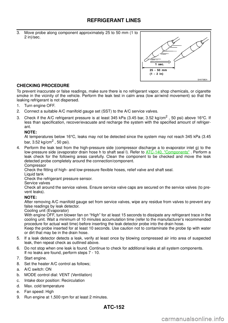
3. Move probe along component approximately 25 to 50 mm (1 to
2 in)/sec.
CHECKING PROCEDURE
To prevent inaccurate or false readings, make sure there is no refrigerant vapor, shop chemicals, or cigarette
smoke in the vicinity of the vehicle. Perform the leak test in calm area (low air/wind movement) so that the
leaking refrigerant is not dispersed.
1. Turn engine OFF.
2. Connect a suitable A/C manifold gauge set (SST) to the A/C service valves.
3. Check if the A/C refrigerant pressure is at least 345 kPa (3.45 bar, 3.52 kg/cm
2,50psi)above16°C. If
less than specification, recover/evacuate and recharge the system with the specified amount of refriger-
ant.
NOTE:
At temperatures below 16°C, leaks may not be detected since the system may not reach 345 kPa (3.45
bar, 3.52 kg/cm
2,50psi).
4. Perform the leak test from the high-pressure side (compressor discharge a to evaporator inlet g) to the
low-pressure side (evaporator drain hose h to shaft seal l). Refer toATC-140, "
Components". Perform a
leak check for the following areas carefully. Clean the component to be checked and move the leak
detected probe completely around the connection/component.
Compressor
Check the fitting of high- and low-pressure flexible hoses, relief valve and shaft seal.
Liquid tank
Check the refrigerant pressure sensor.
Service valves
Check all around the service valves. Ensure service valve caps are secured on the service valves (to pre-
vent leaks).
NOTE:
After removing A/C manifold gauge set from service valves, wipe any residue from valves to prevent any
false readings by leak detector.
Cooling unit (Evaporator)
With engine OFF, turn blower fan on “High” for at least 15 seconds to dissipate any refrigerant trace in the
cooling unit. Wait a minimum of 10 minutes accumulation time (refer to the manufacturer’s recommended
procedure for actual wait time) before inserting the leak detector probe into the drain hose.
Keep the probe inserted for at least 10 seconds. Use caution not to contaminate the probe tip with water
or dirt that may be in the drain hose.
5. If a leak detector detects a leak, verify at least once by blowing compressed air into area of suspected
leak, then repeat check as outlined above.
6. Do not stop when one leak is found. Continue to check for additional leaks at all system components.
If no leaks are found, perform steps 7 - 10.
7. Start engine.
8. Set the heater A/C control as follows;
a. A/C switch: ON
b. MODE control dial: VENT (Ventilation)
c. Intake door position: Recirculation
d. Max. cold temperature
e. Fan speed: High
9. Run engine at 1,500 rpm for at least 2 minutes.
SHA708EA
Page 493 of 3171

SYSTEM DESCRIPTION
AV-5
C
D
E
F
G
H
I
J
L
MA
B
AV
Personal Audio Setting
The radio is designed to store several settings (volume, bass, treble, preset stations) with every NATS ignition
key used. Up to a maximum of 4 NATS keys can be registered. During the communication mentioned under
“Anti-Theft System”, the radio will recognize the used ignition key and select the accompanying settings.
VEHICLE INFORMATION SYSTEM
lThe status of audio system, fuel consumption, rear view monitor and navigation system are displayed.
lNAVI control unit receives the data signal from ECM, combination meter via CAN communication. It calcu-
lates the values of fuel economy, and trip computer from the received information and displays them.
NAVIGATION SYSTEM
Refer to Owner's Manual or navigation system Owner's Manual for navigation system operating instructions.
Location Detection Principle
The navigation system periodically calculates the vehicle's current
position according to the following three signals:
lTravel distance of the vehicle as determined by the vehicle
speed sensor
lTurning angle of the vehicle as determined by the gyroscope
(angular velocity sensor)
lDirection of vehicle travel as determined by the GPS antenna
(GPS information)
The current position of the vehicle is then identified by comparing the
calculated vehicle position with map data read from the map DVD-
ROM, which is stored in the DVD-ROM drive (map-matching), and
indicated on the screen as a vehicle mark. More accurate data is judged and used by comparing vehicle posi-
tion detection results found by the GPS with the result by map-matching.
The current vehicle position will be calculated by detecting the dis-
tance the vehicle moved from the previous calculation point and its
direction.
lTravel distance
Travel distance calculations are based on the vehicle speed
sensor input signal. Therefore, the calculation may become
incorrect as the tires wear down. To prevent this, an automatic
distance correction function has been adopted.
lTravel direction
Change in the travel direction of the vehicle is calculated by a
gyroscope (angular velocity sensor) and a GPS antenna (GPS
information). They have both advantages and disadvantages.
More accurate traveling direction is detected because priorities are set for the signals from these two
devices according to the situation.
No communication from IMMU to radio 1. If NATS is malfunctioning, check NATS
system.
2. After NATS is repaired, reset radio to
NEW state by authorized representative
of Clarion.After switching on the radio, the radio will
display “SECURE” after 1 minute. Further
use of radio is impossible until communica-
tion is established again, or after radio is
reset by authorized representative of Clar-
ion.
When initialized between ECM and IMMU. Radio needs to be reset to NEW status by
authorized representative of Clarion.After switching on the radio, it will display
“SECURE” after 1 minute. Item Service procedure Description
SKIB1058E
Type Advantage Disadvantage
Gyroscope
(angular velocity sensor)Can detect the vehicle's turning angle
quite accurately.Direction errors may accumulate when vehicle is
driven for long distances without stopping.
GPS antenna
(GPS information)Can detect the vehicle's travel direction
(North/South/East/West).Correct direction cannot be detected when vehi-
cle speed is low.
SEL684V
Page 496 of 3171

AV-8
SYSTEM DESCRIPTION
Component Description
EKS00Q5Y
AUDIO UNIT
Perform AUDIO operation by AV SWITCH for models with navigation system.
NAVI CONTROL UNIT
lThe gyro (angular speed sensor) and the DVD-ROM drive are
built-in units that control the navigation functions.
lSignals are received from the gyro, the vehicle speed sensor,
and the GPS antenna. Vehicle location is determined by com-
bining this data with the data contained in the DVD-ROM map.
Locational information is shown on liquid crystal display panel.
DVD-ROM Drive
lDVD loading slot (1)
Maps, traffic control regulations, and other pertinent information can
be easily read from the DVD-ROM disc.
Map DVD-ROM
lThe map DVD-ROM has maps, traffic control regulations, and other pertinent information.
lTo improve DVD-ROM map matching and route determination functions, the DVD-ROM uses an exclusive
Nissan format. Therefore, the use of a DVD-ROM provided by other manufacturers cannot be used.
Gyro (Angular Speed Sensor)
lThe oscillator gyro sensor is used to detect changes in vehicle steering angle.
lThe gyro is built into the navigation (NAVI) control unit.
1. 1CD player type 2. 6CD player type 3. 6CD player type (With navigation
system)
SKIB4066E
SKIB4067E
SKIB4068E
Page 554 of 3171

AV-66
TROUBLE DIAGNOSIS
MAP DVD-ROM
ROUTE CALCULATION AND VISUAL GUIDANCE
Thelocationofvehicleiconismis-
aligned from the actual position.When using tire chains or replacing the tires, speed
calculations based on the speed sensor may be
incorrect.Drive the vehicle for a while [at approxi-
mately 30 km/h (19 MPH) for about 30
minutes] to automatically correct the vehi-
cle icon position.
If this does not correct the vehicle icon
position, contact an NISSAN dealer.
The map data has mistake or is incomplete (the
vehicle icon position is always misaligned in the
same area).Updated road information will be included
in the next version of the map DVD-ROM. Symptom Possible cause Possible solution
Symptom Possible cause Possible solution
The message “Error” appears. Map DVD-ROM is dirty or partially damaged.Check the DVD-ROM and wipe it clean
with a soft cloth.
If there is any damage, replace the DVD-
ROM.
Symptom Possible cause Possible solution
In the auto reroute calculation,
waypoints are not included.Waypoints already passed are not included in the
auto reroute calculation.In case of going to that waypoints again,
edit the route.
Route information is not displayed.Route calculation has not yet been performed.Set the destination and perform route cal-
culation.
The vehicle is not driven on the suggested route. Drive on the suggested route.
Route guidance is set to off. Turn on route guidance.
Route information is not provided for narrow streets
(roads displayed in gray).This is not a malfunction.
The auto reroute calculation (or
detour calculation) suggests the
same route as the one previously
suggested.Route calculation took priority conditions into con-
sideration, but the same route was calculated.This is not a malfunction.
A waypoint cannot be added.Five waypoints are already set on the route, includ-
ing ones that already passed.A maximum of 5 waypoints can be set on
the route. In case of going to 6 or more
waypoints, perform route calculations mul-
tiple times as necessary.
The suggested route is not dis-
played.Roads near the destination cannot be calculated.Reset the destination to a main or ordinary
road, and recalculate the route.
The starting point and destination are too close. Set a more distant destination.
The starting point and destination are too far away.Divide the way by selecting one or two
intermediate destinations, and perform
route calculations multiple times.
There are time restricted roads (by day of week, by
time) near the current vehicle location or destina-
toin.Set Use Time Restricted Roads to off.
A part of the route is not displayed.The suggested route includes narrow streets (roads
displayed in gray).This is not a malfunction.
The part of the route already
passed is deleted.A route is managed by sections between way-
points. If you passed the first waypoint, the section
between the starting point and the waypoint is
deleted. (It may not be deleted depending on the
area.)This is not a malfunction.