Page 439 of 3171
TROUBLE DIAGNOSIS
ATC-105
C
D
E
F
G
H
I
K
L
MA
B
AT C
Ambient Sensor CircuitEJS006BW
COMPONENT DESCRIPTION
Ambient Sensor
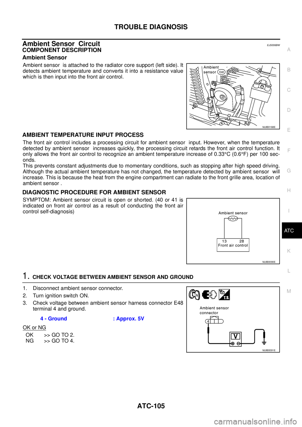
Ambient sensor is attached to the radiator core support (left side). It
detects ambient temperature and converts it into a resistance value
which is then input into the front air control.
AMBIENT TEMPERATURE INPUT PROCESS
The front air control includes a processing circuit for ambient sensor input. However, when the temperature
detected by ambient sensor increases quickly, the processing circuit retards the front air control function. It
only allows the front air control to recognize an ambient temperature increase of 0.33°C(0.6°F) per 100 sec-
onds.
This prevents constant adjustments due to momentary conditions, such as stopping after high speed driving.
Although the actual ambient temperature has not changed, the temperature detected by ambient sensor will
increase. This is because the heat from the engine compartment can radiate to the front grille area, location of
ambient sensor .
DIAGNOSTIC PROCEDURE FOR AMBIENT SENSOR
SYMPTOM: Ambient sensor circuit is open or shorted. (40 or 41 is
indicated on front air control as a result of conducting the front air
control self-diagnosis)
1.CHECK VOLTAGE BETWEEN AMBIENT SENSOR AND GROUND
1. Disconnect ambient sensor connector.
2. Turn ignition switch ON.
3. Check voltage between ambient sensor harness connector E48
terminal 4 and ground.
OK or NG
OK >> GO TO 2.
NG >> GO TO 4.
MJIB0168E
MJIB0090E
4 - Ground : Approx. 5V
MJIB0091E
Page 440 of 3171
ATC-106
TROUBLE DIAGNOSIS
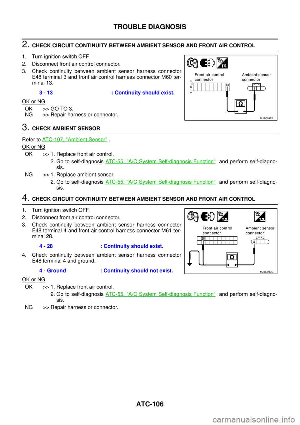
2.CHECK CIRCUIT CONTINUITY BETWEEN AMBIENT SENSOR AND FRONT AIR CONTROL
1. Turn ignition switch OFF.
2. Disconnect front air control connector.
3. Check continuity between ambient sensor harness connector
E48 terminal 3 and front air control harness connector M60 ter-
minal 13.
OK or NG
OK >> GO TO 3.
NG >> Repair harness or connector.
3.CHECK AMBIENT SENSOR
Refer toATC-107, "
Ambient Sensor".
OK or NG
OK >> 1. Replace front air control.
2. Go to self-diagnosisAT C - 5 5 , "
A/C System Self-diagnosis Function"and perform self-diagno-
sis.
NG >> 1. Replace ambient sensor.
2. Go to self-diagnosisAT C - 5 5 , "
A/C System Self-diagnosis Function"and perform self-diagno-
sis.
4.CHECK CIRCUIT CONTINUITY BETWEEN AMBIENT SENSOR AND FRONT AIR CONTROL
1. Turn ignition switch OFF.
2. Disconnect front air control connector.
3. Check continuity between ambient sensor harness connector
E48 terminal 4 and front air control harness connector M61 ter-
minal 28.
4. Check continuity between ambient sensor harness connector
E48 terminal 4 and ground.
OK or NG
OK >> 1. Replace front air control.
2. Go to self-diagnosisAT C - 5 5 , "
A/C System Self-diagnosis Function"and perform self-diagno-
sis.
NG >> Repair harness or connector.3 - 13 : Continuity should exist.
MJIB0092E
4 - 28 : Continuity should exist.
4 - Ground : Continuity should not exist.
MJIB0093E
Page 441 of 3171
TROUBLE DIAGNOSIS
ATC-107
C
D
E
F
G
H
I
K
L
MA
B
AT C
COMPONENT INSPECTION
Ambient Sensor
After disconnecting ambient sensor connector, measure resistance
between terminals 1 and 2 at sensor component side, using the table
below.
If NG, replace ambient sensor .
Temperature°C(°F) Resistance kW
0(32) 9.39
20 (68) 3.51
35 (95) 1.80
40 (104) 1.46
MJIB0169E
Page 442 of 3171
ATC-108
TROUBLE DIAGNOSIS
In-vehicle Sensor Circuit
EJS006BX
COMPONENT DESCRIPTION
In-vehicle Sensor
The in-vehicle sensor is located on instrument lower driver panel. It
converts variations in temperature of passenger compartment air
(drawn in through the integrated fan) into a resistance value. It is
then input into the front air control.
MJIB0352E
WJIA0606E
Page 443 of 3171
TROUBLE DIAGNOSIS
ATC-109
C
D
E
F
G
H
I
K
L
MA
B
AT C
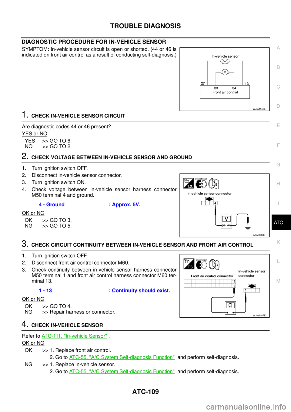
DIAGNOSTIC PROCEDURE FOR IN-VEHICLE SENSOR
SYMPTOM: In-vehicle sensor circuit is open or shorted. (44 or 46 is
indicated on front air control as a result of conducting self-diagnosis.)
1.CHECK IN-VEHICLE SENSOR CIRCUIT
Are diagnostic codes 44 or 46 present?
YES or NO
YES >> GO TO 6.
NO >> GO TO 2.
2.CHECK VOLTAGE BETWEEN IN-VEHICLE SENSOR AND GROUND
1. Turn ignition switch OFF.
2. Disconnect in-vehicle sensor connector.
3. Turn ignition switch ON.
4. Check voltage between in-vehicle sensor harness connector
M50 terminal 4 and ground.
OK or NG
OK >> GO TO 3.
NG >> GO TO 5.
3.CHECK CIRCUIT CONTINUITY BETWEEN IN-VEHICLE SENSOR AND FRONT AIR CONTROL
1. Turn ignition switch OFF.
2. Disconnect front air control connector M60.
3. Check continuity between in-vehicle sensor harness connector
M50 terminal 1 and front air control harness connector M60 ter-
minal 13.
OK or NG
OK >> GO TO 4.
NG >> Repair harness or connector.
4.CHECK IN-VEHICLE SENSOR
Refer toAT C - 111 , "
In-vehicle Sensor".
OK or NG
OK >> 1. Replace front air control.
2. Go toAT C - 5 5 , "
A/C System Self-diagnosis Function"and perform self-diagnosis.
NG >> 1. Replace in-vehicle sensor.
2. Go toAT C - 5 5 , "
A/C System Self-diagnosis Function"and perform self-diagnosis.
WJIA1146E
4 - Ground : Approx. 5V.
LJIA0089E
1 - 13 : Continuity should exist.
WJIA1147E
Page 444 of 3171
ATC-110
TROUBLE DIAGNOSIS
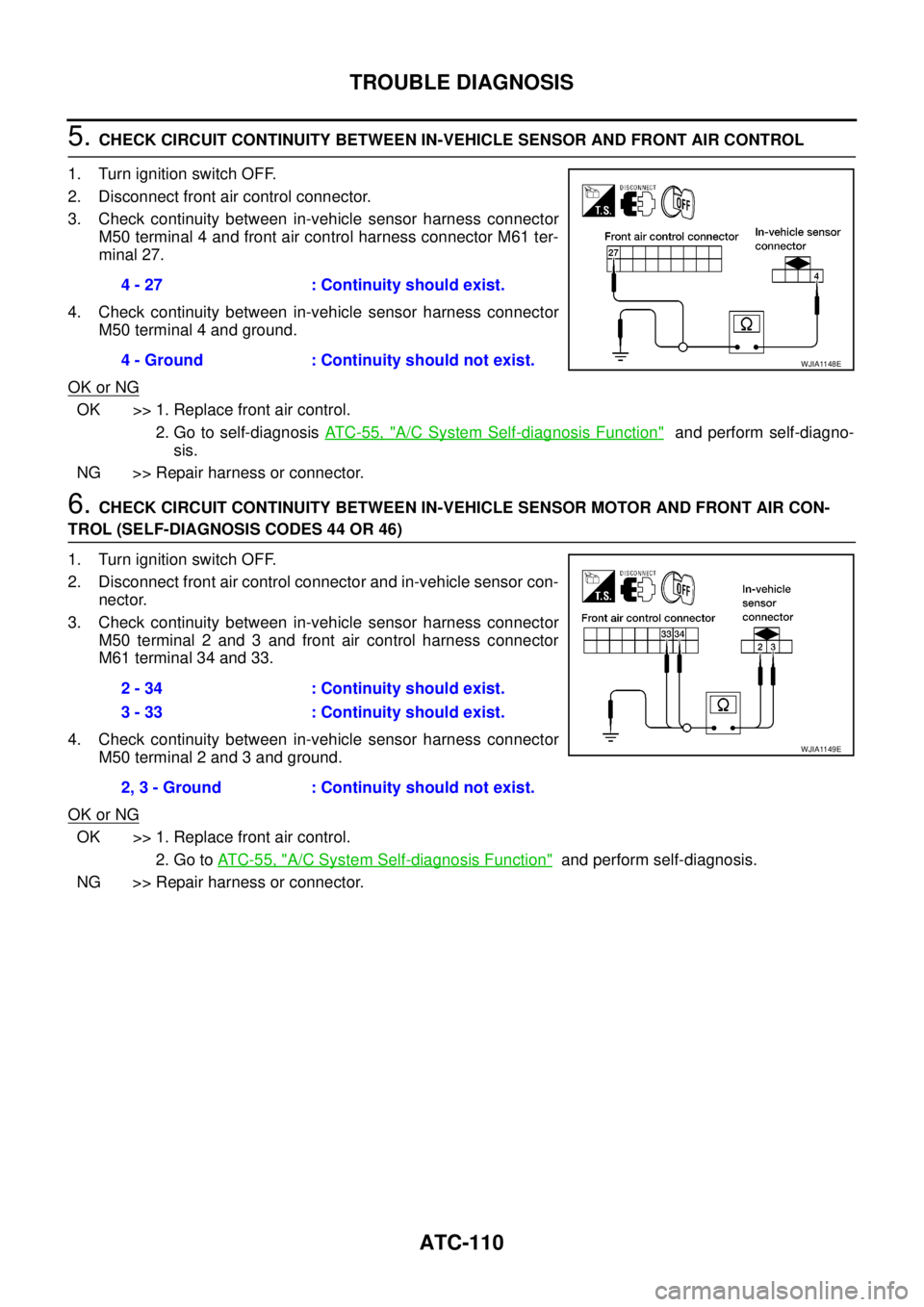
5.CHECK CIRCUIT CONTINUITY BETWEEN IN-VEHICLE SENSOR AND FRONT AIR CONTROL
1. Turn ignition switch OFF.
2. Disconnect front air control connector.
3. Check continuity between in-vehicle sensor harness connector
M50 terminal 4 and front air control harness connector M61 ter-
minal 27.
4. Check continuity between in-vehicle sensor harness connector
M50 terminal 4 and ground.
OK or NG
OK >> 1. Replace front air control.
2. Go to self-diagnosisAT C - 5 5 , "
A/C System Self-diagnosis Function"and perform self-diagno-
sis.
NG >> Repair harness or connector.
6.CHECK CIRCUIT CONTINUITY BETWEEN IN-VEHICLE SENSOR MOTOR AND FRONT AIR CON-
TROL (SELF-DIAGNOSIS CODES 44 OR 46)
1. Turn ignition switch OFF.
2. Disconnect front air control connector and in-vehicle sensor con-
nector.
3. Check continuity between in-vehicle sensor harness connector
M50 terminal 2 and 3 and front air control harness connector
M61 terminal 34 and 33.
4. Check continuity between in-vehicle sensor harness connector
M50 terminal 2 and 3 and ground.
OK or NG
OK >> 1. Replace front air control.
2. Go toAT C - 5 5 , "
A/C System Self-diagnosis Function"and perform self-diagnosis.
NG >> Repair harness or connector.4 - 27 : Continuity should exist.
4 - Ground : Continuity should not exist.
WJIA1148E
2 - 34 : Continuity should exist.
3 - 33 : Continuity should exist.
2, 3 - Ground : Continuity should not exist.
WJIA1149E
Page 445 of 3171
TROUBLE DIAGNOSIS
ATC-111
C
D
E
F
G
H
I
K
L
MA
B
AT C
COMPONENT INSPECTION
In-vehicle Sensor
After disconnecting in-vehicle sensor connector, measure resistance
between terminals 1 and 4 at sensor component side, using the table
below.
If NG, replace in-vehicle sensor.
Temperature°C(°F) Resistance kW
-15 (5) 21.40
-10 (14) 16.15
-5 (23) 12.29
0(32) 9.41
5(41) 7.27
10 (50) 5.66
15 (59) 4.45
20 (68) 3.51
25 (77) 2.79
30 (86) 2.24
35 (95) 1.80
40 (104) 1.45
45 (113) 1.18
MJIB0353E
Page 446 of 3171
ATC-112
TROUBLE DIAGNOSIS
Optical Sensor Circuit
EJS006BY
COMPONENT DESCRIPTION
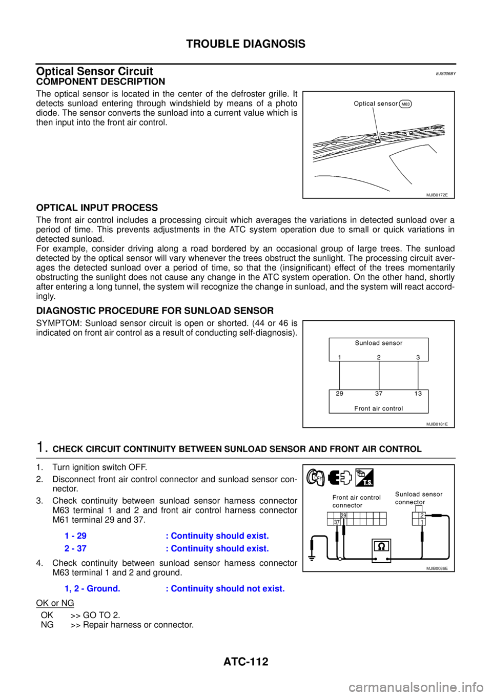
The optical sensor is located in the center of the defroster grille. It
detects sunload entering through windshield by means of a photo
diode. The sensor converts the sunload into a current value which is
then input into the front air control.
OPTICAL INPUT PROCESS
The front air control includes a processing circuit which averages the variations in detected sunload over a
period of time. This prevents adjustments in the ATC system operation due to small or quick variations in
detected sunload.
For example, consider driving along a road bordered by an occasional group of large trees. The sunload
detected by the optical sensor will vary whenever the trees obstruct the sunlight. The processing circuit aver-
ages the detected sunload over a period of time, so that the (insignificant) effect of the trees momentarily
obstructing the sunlight does not cause any change in the ATC system operation. On the other hand, shortly
after entering a long tunnel, the system will recognize the change in sunload, and the system will react accord-
ingly.
DIAGNOSTIC PROCEDURE FOR SUNLOAD SENSOR
SYMPTOM: Sunload sensor circuit is open or shorted. (44 or 46 is
indicated on front air control as a result of conducting self-diagnosis).
1.CHECK CIRCUIT CONTINUITY BETWEEN SUNLOAD SENSOR AND FRONT AIR CONTROL
1. Turn ignition switch OFF.
2. Disconnect front air control connector and sunload sensor con-
nector.
3. Check continuity between sunload sensor harness connector
M63 terminal 1 and 2 and front air control harness connector
M61 terminal 29 and 37.
4. Check continuity between sunload sensor harness connector
M63 terminal 1 and 2 and ground.
OK or NG
OK >> GO TO 2.
NG >> Repair harness or connector.
MJIB0172E
MJIB0181E
1 - 29 : Continuity should exist.
2 - 37 : Continuity should exist.
1, 2 - Ground. : Continuity should not exist.
MJIB0086E