2005 NISSAN NAVARA sensor
[x] Cancel search: sensorPage 337 of 3171

ATC-3
C
D
E
F
G
H
I
K
L
MA
B
AT C BLOWER MOTOR .................................................. 121
Components ......................................................... 121
Removal and Installation ...................................... 121
REMOVAL ......................................................... 121
INSTALLATION ................................................. 121
AIR CONDITIONER FILTER ................................... 122
Removal and Installation ...................................... 122
FUNCTION ........................................................ 122
REPLACEMENT TIMING .................................. 122
REPLACEMENT PROCEDURE ....................... 122
HEATER & COOLING UNIT ASSEMBLY .............. 124
Components ......................................................... 124
Removal and Installation ...................................... 126
REMOVAL ......................................................... 126
INSTALLATION ................................................. 126
HEATER CORE ...................................................... 127
Components ......................................................... 127
Removal and Installation ...................................... 127
REMOVAL ......................................................... 127
INSTALLATION ................................................. 127
HEATER PUMP ...................................................... 128
Components ......................................................... 128
Removal and Installation ...................................... 128
REMOVAL ......................................................... 128
INSTALLATION ................................................. 128
INTAKE DOOR MOTOR ......................................... 129
Components ......................................................... 129
Removal and Installation ...................................... 129
REMOVAL ......................................................... 129
INSTALLATION ................................................. 129
MODE DOOR MOTOR ........................................... 130
Components ......................................................... 130
Removal and Installation ...................................... 130
REMOVAL ......................................................... 130
INSTALLATION ................................................. 130
AIR MIX DOOR MOTOR ......................................... 131
Components ......................................................... 131
Removal and Installation ...................................... 131
AIR MIX DOOR MOTOR (DRIVER) .................. 131
AIR MIX DOOR MOTOR (PASSENGER) ......... 131
VARIABLE BLOWER CONTROL .......................... 133
Components ......................................................... 133
Removal and Installation ...................................... 133
REMOVAL ......................................................... 133
INSTALLATION ................................................. 133
DUCTS AND GRILLES .......................................... 134
Components ......................................................... 134
Removal and Installation ...................................... 136
CONSOLE DUCTS AND CONSOLE GRILLE .. 136
DEFROSTER NOZZLE ..................................... 136
RH AND LH SIDE DEMISTER DUCT ............... 136
RH AND LH VENTILATOR DUCT ..................... 136
CENTER VENTILATOR DUCT ......................... 136
FLOOR CONNECTOR DUCT ........................... 136
FRONT AND REAR FLOOR DUCTS ............... 137
REAR OVERHEAD DUCTS .............................. 137
SIDE REAR FLOOR DUCT .............................. 137
GRILLES ........................................................... 137REFRIGERANT LINES ...........................................138
HFC-134a (R-134a) Service Procedure ...............138
SETTING OF SERVICE TOOLS AND EQUIP-
MENT ................................................................138
Components .........................................................140
Removal and Installation for Compressor ............142
REMOVAL .........................................................142
INSTALLATION .................................................142
Removal and Installation for Compressor Clutch . 143
REMOVAL .........................................................143
INSPECTION ....................................................144
INSTALLATION .................................................144
BREAK-IN OPERATION ....................................146
Removal and Installation for High-pressure Flexible
A/C Hose ..............................................................146
REMOVAL .........................................................146
INSTALLATION .................................................146
Removal and Installation for High-pressure A/C
Pipe ......................................................................146
REMOVAL .........................................................146
INSTALLATION .................................................146
Removal and Installation for Low-pressure Flexible
A/C Hose ..............................................................146
REMOVAL .........................................................146
INSTALLATION .................................................146
Removal and Installation for Low-pressure A/C Pipe.147
REMOVAL .........................................................147
INSTALLATION .................................................147
Removal and Installation for Refrigerant Pressure
Sensor ..................................................................147
REMOVAL .........................................................147
INSTALLATION .................................................147
Removal and Installation for Condenser ..............147
REMOVAL .........................................................147
INSTALLATION .................................................148
Removal and Installation for Evaporator ..............149
REMOVAL .........................................................149
INSTALLATION .................................................149
Removal and Installation for Expansion Valve ......150
REMOVAL .........................................................150
INSTALLATION .................................................150
Checking for Refrigerant Leaks ............................150
Checking System for Leaks Using the Fluorescent
Leak Detector .......................................................150
Dye Injection .........................................................151
Electronic Refrigerant Leak Detector ....................151
PRECAUTIONS FOR HANDLING LEAK
DETECTOR .......................................................151
CHECKING PROCEDURE ...............................152
SERVICE DATA AND SPECIFICATIONS (SDS) ....154
Service Data and Specifications (SDS) ................154
COMPRESSOR ................................................154
LUBRICANT ......................................................154
REFRIGERANT .................................................154
ENGINE IDLING SPEED ..................................154
BELT TENSION .................................................154
Page 339 of 3171
PRECAUTIONS
ATC-5
C
D
E
F
G
H
I
K
L
MA
B
AT C
lIf the vehicle is within the warranty period, the air conditioner warranty is void. Please contact NISSAN
Customer Affairs for further assistance.
General Refrigerant PrecautionsEJS006AN
WARNING:
lDo not release refrigerant into the air. Use approved recovery/recycling equipment to capture the
refrigerant every time an air conditioning system is discharged.
lAlways wear eye and hand protection (goggles and gloves) when working with any refrigerant or
air conditioning system.
lDo not store or heat refrigerant containers above 52°C.
lDo not heat a refrigerant container with an open flame; if container warming is required, place the
bottom of the container in a warm pail of water.
lDo not intentionally drop, puncture, or incinerate refrigerant containers.
lKeep refrigerant away from open flames: poisonous gas will be produced if refrigerant burns.
lRefrigerant will displace oxygen, therefore be certain to work in well ventilated areas to prevent
suffocation.
lDo not pressure test or leak test HFC-134a (R-134a) service equipment and/or vehicle air condi-
tioning systems with compressed air during repair. Some mixtures of air and HFC-134a (R-134a)
have been shown to be combustible at elevated pressures. These mixtures, if ignited, may cause
injury or property damage. Additional health and safety information may be obtained from refriger-
ant manufacturers.
Precautions for Refrigerant ConnectionEJS006AO
A new type refrigerant connection has been introduced to all refrigerant lines except the following locations.
lExpansion valve to cooling unit
lEvaporator pipes to evaporator (inside cooling unit)
lRefrigerant pressure sensor
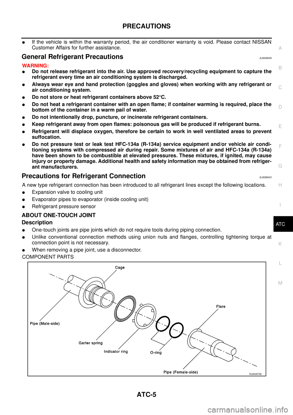
ABOUT ONE-TOUCH JOINT
Description
lOne-touch joints are pipe joints which do not require tools during piping connection.
lUnlike conventional connection methods using union nuts and flanges, controlling tightening torque at
connection point is not necessary.
lWhen removing a pipe joint, use a disconnector.
COMPONENT PARTS
RJIA0970E
Page 343 of 3171
PRECAUTIONS
ATC-9
C
D
E
F
G
H
I
K
L
MA
B
AT C
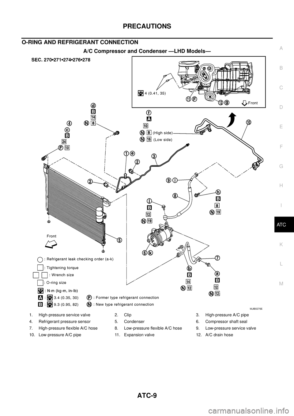
O-RING AND REFRIGERANT CONNECTION
A/C Compressor and Condenser —LHD Models—
MJIB0276E
1. High-pressure service valve 2. Clip 3. High-pressure A/C pipe
4. Refrigerant pressure sensor 5. Condenser 6. Compressor shaft seal
7. High-pressure flexible A/C hose 8. Low-pressure flexible A/C hose 9. Low-pressure service valve
10. Low-pressure A/C pipe 11. Expansion valve 12. A/C drain hose
Page 344 of 3171
ATC-10
PRECAUTIONS
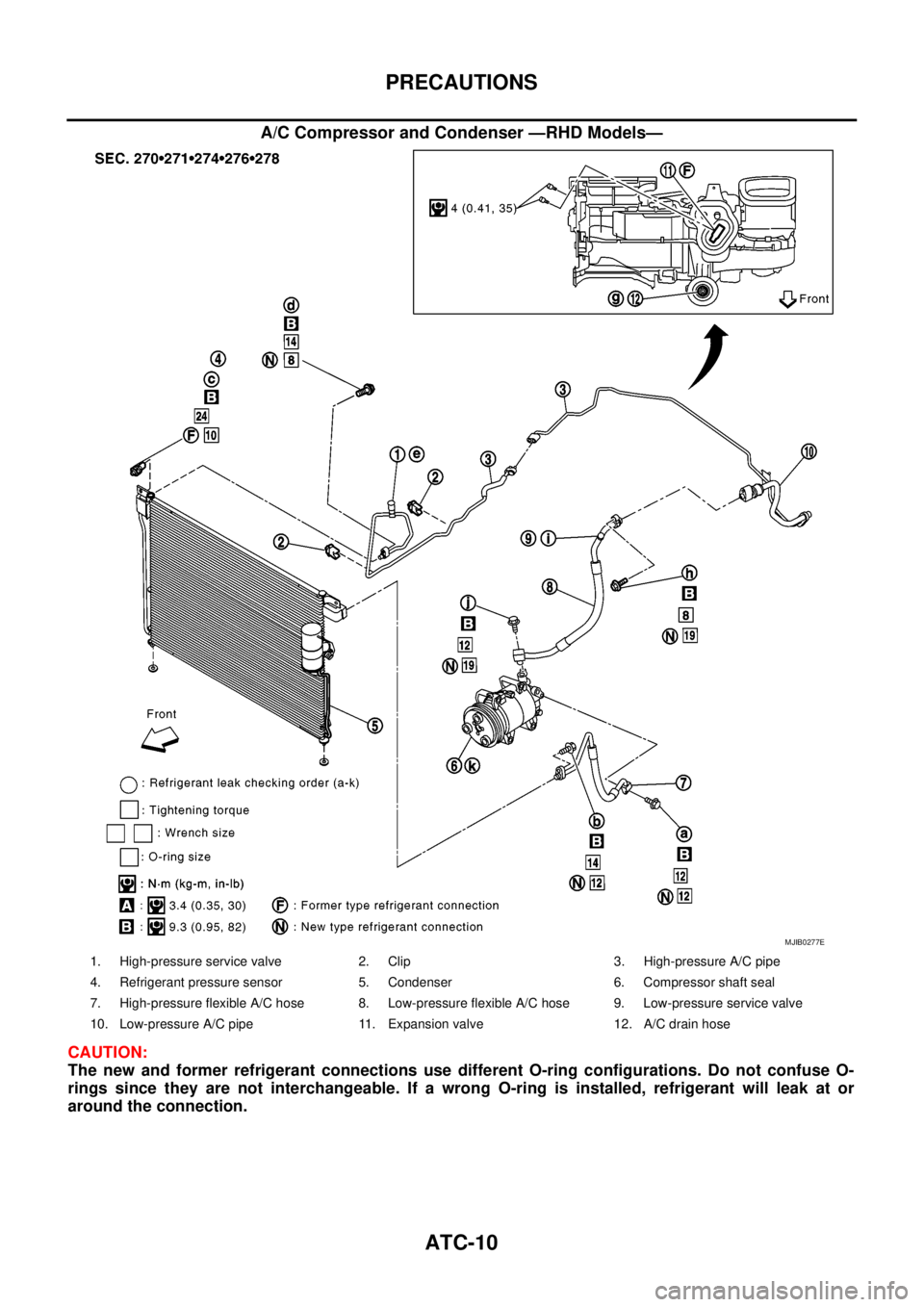
A/C Compressor and Condenser —RHD Models—
CAUTION:
The new and former refrigerant connections use different O-ring configurations. Do not confuse O-
rings since they are not interchangeable. If a wrong O-ring is installed, refrigerant will leak at or
around the connection.
MJIB0277E
1. High-pressure service valve 2. Clip 3. High-pressure A/C pipe
4. Refrigerant pressure sensor 5. Condenser 6. Compressor shaft seal
7. High-pressure flexible A/C hose 8. Low-pressure flexible A/C hose 9. Low-pressure service valve
10. Low-pressure A/C pipe 11. Expansion valve 12. A/C drain hose
Page 354 of 3171

ATC-20
REFRIGERATION SYSTEM
REFRIGERATION SYSTEM
PFP:KA990
Refrigerant CycleEJS006AW
REFRIGERANT FLOW
The refrigerant flows in the standard pattern, that is, through the compressor, the condenser with liquid tank,
through the evaporator, and back to the compressor. The refrigerant evaporation through the evaporator is
controlled by an externally equalized expansion valve, located inside the evaporator case.
FREEZE PROTECTION
Under usual operating conditions, when the A/C is switched ON, the compressor runs continuously, and the
evaporator pressure, and therefore, temperature is controlled by the V-6 variable displacement compressor to
prevent freeze up.
Refrigerant System ProtectionEJS006AX
REFRIGERANT PRESSURE SENSOR
The refrigerant system is protected against excessively high or low pressures by the refrigerant pressure sen-
sor, located on the condenser. If the system pressure rises above or falls below the specifications, the refriger-
ant pressure sensor detects the pressure inside the refrigerant line and sends a voltage signal to the ECM.
The ECM de-energizes the A/C relay to disengage the magnetic compressor clutch when pressure on the high
pressure side detected by refrigerant pressure sensor is over about 2,746 kPa (28 kg/cm
2, 398 psi), or below
about 120 kPa (1.22 kg/cm
2,17.4psi).
Page 360 of 3171

ATC-26
AIR CONDITIONER CONTROL
AIR CONDITIONER CONTROL
PFP:27500
DescriptionEJS006B0
The front air control provides automatic regulation of the vehicle's interior temperature. The system is based
on the driver's and passenger's selected “set temperature”, regardless of the outside temperature changes.
This is done by utilizing a microcomputer, also referred to as the front air control, which receives input signals
from the following six sensors:
lAmbient sensor
lIn-vehicle sensor
lIntake sensor
lOptical sensor (one sensor for driver and passenger side)
lPBR (Position Balanced Resistor).
lVehicle speed sensor
The front air control uses these signals (including the set temperature) to automatically control:
lOutlet air volume
lAir temperature
lAir distribution
The front air control is used to select:
lOutlet air volume
lAir temperature/distribution
OperationEJS006B1
AIR MIX DOORS CONTROL
The air mix doors are automatically controlled so that in-vehicle temperature is maintained at a predetermined
value by the temperature setting, ambient temperature, in-vehicle temperature and amount of sunload.
BLOWER SPEED CONTROL
Blower speed is automatically controlled by the temperature setting, ambient temperature, in-vehicle tempera-
ture, intake temperature, amount of sunload and air mix door position.
When AUTO switch is pressed, the blower motor starts to gradually increase air flow volume (if required).
When engine coolant temperature is low, the blower motor operation is delayed to prevent cool air from flow-
ing.
INTAKE DOOR CONTROL
The intake door is automatically controlled by the temperature setting, ambient temperature, in-vehicle tem-
perature, intake temperature, amount of sunload and the ON-OFF operation of the compressor.
MODE DOOR CONTROL
The mode door is automatically controlled by the temperature setting, ambient temperature, in-vehicle temper-
ature, intake temperature and amount of sunload.
DEFROSTER DOOR CONTROL
The defroster door is controlled by: Turning the defroster dial to front defroster.
Page 361 of 3171
AIR CONDITIONER CONTROL
ATC-27
C
D
E
F
G
H
I
K
L
MA
B
AT C
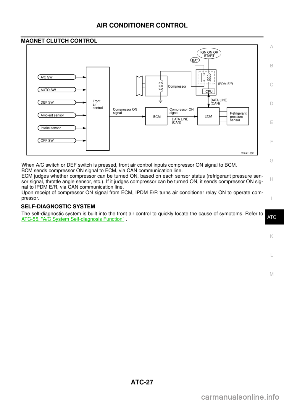
MAGNET CLUTCH CONTROL
When A/C switch or DEF switch is pressed, front air control inputs compressor ON signal to BCM.
BCM sends compressor ON signal to ECM, via CAN communication line.
ECM judges whether compressor can be turned ON, based on each sensor status (refrigerant pressure sen-
sor signal, throttle angle sensor, etc.). If it judges compressor can be turned ON, it sends compressor ON sig-
nal to IPDM E/R, via CAN communication line.
Upon receipt of compressor ON signal from ECM, IPDM E/R turns air conditioner relay ON to operate com-
pressor.
SELF-DIAGNOSTIC SYSTEM
The self-diagnostic system is built into the front air control to quickly locate the cause of symptoms. Refer to
AT C - 5 5 , "
A/C System Self-diagnosis Function".
WJIA1163E
Page 362 of 3171
ATC-28
AIR CONDITIONER CONTROL
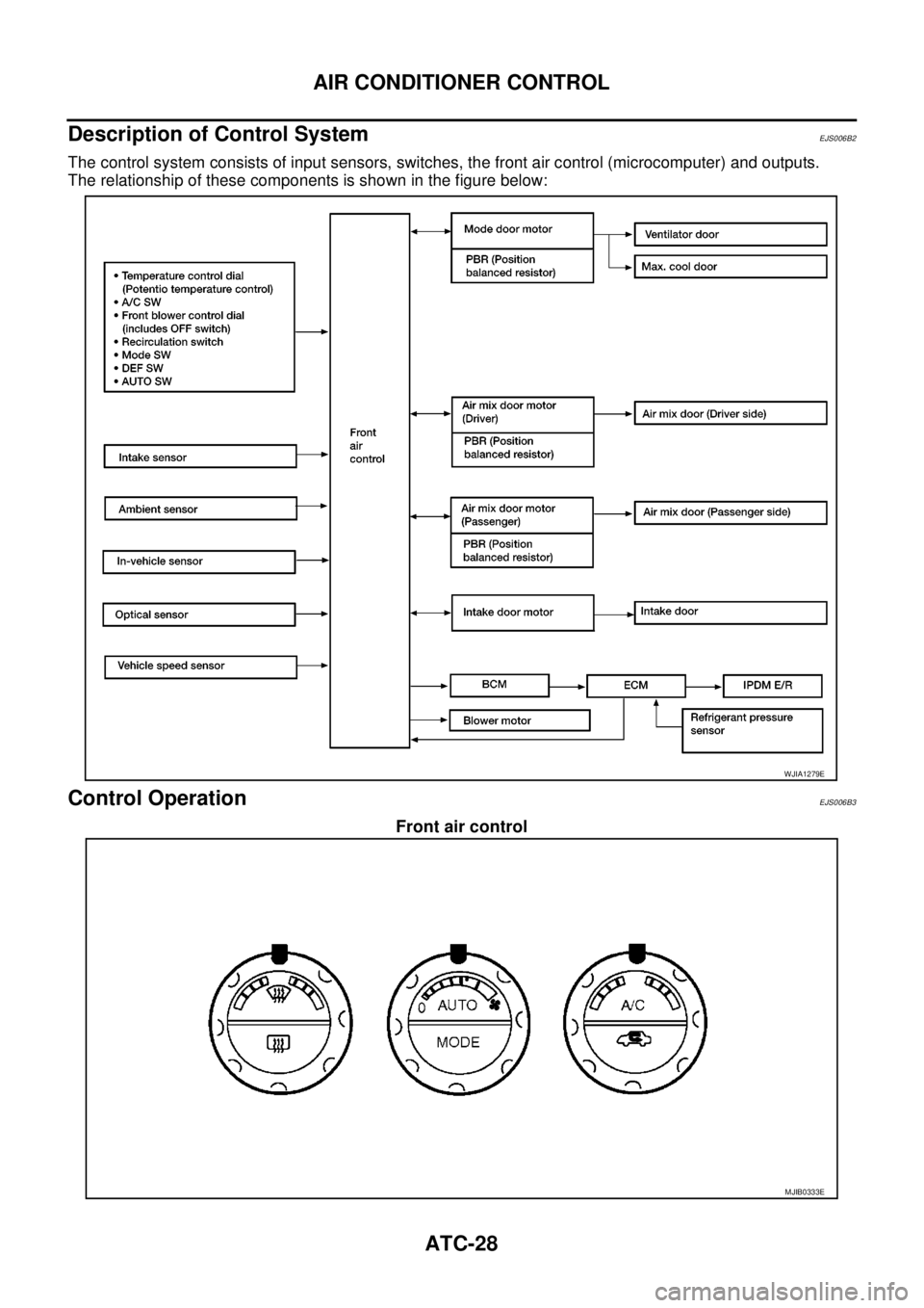
Description of Control System
EJS006B2
The control system consists of input sensors, switches, the front air control (microcomputer) and outputs.
The relationship of these components is shown in the figure below:
Control OperationEJS006B3
Front air control
WJIA1279E
MJIB0333E