Page 447 of 3171
TROUBLE DIAGNOSIS
ATC-113
C
D
E
F
G
H
I
K
L
MA
B
AT C
2.CHECK CIRCUIT CONTINUITY BETWEEN SUNLOAD SENSOR AND FRONT AIR CONTROL
1. Turn ignition switch OFF.
2. Disconnect front air control connector and sunload sensor con-
nector.
3. Check continuity between sunload sensor harness connector
M63 terminal 3 and front air control harness connector M60 ter-
minal 13.
4. Check continuity between sunload sensor harness connector
M63 terminal 3 and ground.
OK or NG
OK >> Replace sunload sensor.
NG >> Repair harness or connector.3 - 13 : Continuity should exist.
3 - Ground : Continuity should not exist.
MJIB0087E
Page 448 of 3171

ATC-114
TROUBLE DIAGNOSIS
Intake Sensor Circuit
EJS006BZ
COMPONENT DESCRIPTION
Intake Sensor
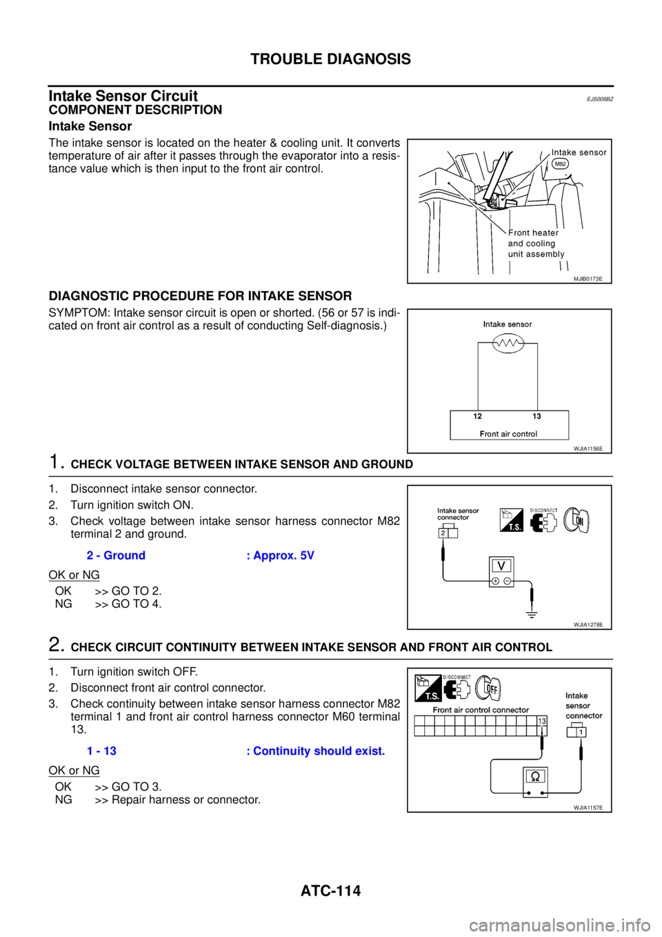
The intake sensor is located on the heater & cooling unit. It converts
temperature of air after it passes through the evaporator into a resis-
tance value which is then input to the front air control.
DIAGNOSTIC PROCEDURE FOR INTAKE SENSOR
SYMPTOM: Intake sensor circuit is open or shorted. (56 or 57 is indi-
cated on front air control as a result of conducting Self-diagnosis.)
1.CHECK VOLTAGE BETWEEN INTAKE SENSOR AND GROUND
1. Disconnect intake sensor connector.
2. Turn ignition switch ON.
3. Check voltage between intake sensor harness connector M82
terminal 2 and ground.
OK or NG
OK >> GO TO 2.
NG >> GO TO 4.
2.CHECK CIRCUIT CONTINUITY BETWEEN INTAKE SENSOR AND FRONT AIR CONTROL
1. Turn ignition switch OFF.
2. Disconnect front air control connector.
3. Check continuity between intake sensor harness connector M82
terminal 1 and front air control harness connector M60 terminal
13.
OK or NG
OK >> GO TO 3.
NG >> Repair harness or connector.
MJIB0173E
WJIA1156E
2 - Ground : Approx. 5V
WJIA1278E
1 - 13 : Continuity should exist.
WJIA1157E
Page 449 of 3171

TROUBLE DIAGNOSIS
ATC-115
C
D
E
F
G
H
I
K
L
MA
B
AT C
3.CHECK INTAKE SENSOR
Refer toAT C - 11 5 , "
Intake Sensor".
OK or NG
OK >> 1. Replace front air control.
2. Go to self-diagnosisAT C - 5 5 , "
A/C System Self-diagnosis Function"and perform self-diagno-
sis.
NG >> 1. Replace intake sensor.
2. Go to self-diagnosisAT C - 5 5 , "
A/C System Self-diagnosis Function"and perform self-diagno-
sis.
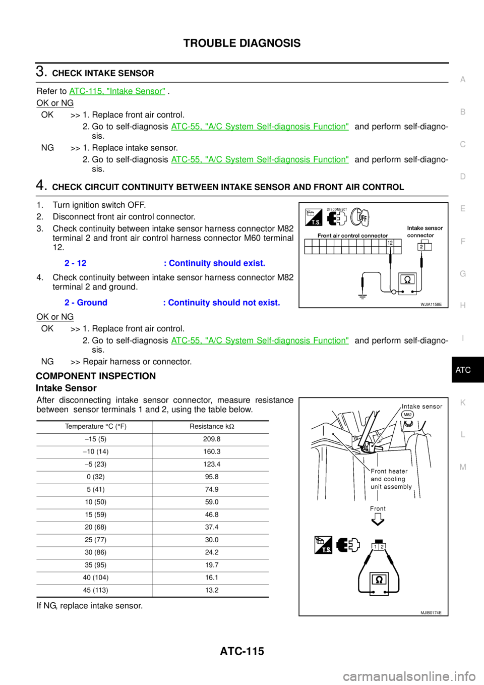
4.CHECK CIRCUIT CONTINUITY BETWEEN INTAKE SENSOR AND FRONT AIR CONTROL
1. Turn ignition switch OFF.
2. Disconnect front air control connector.
3. Check continuity between intake sensor harness connector M82
terminal 2 and front air control harness connector M60 terminal
12.
4. Check continuity between intake sensor harness connector M82
terminal 2 and ground.
OK or NG
OK >> 1. Replace front air control.
2. Go to self-diagnosisAT C - 5 5 , "
A/C System Self-diagnosis Function"and perform self-diagno-
sis.
NG >> Repair harness or connector.
COMPONENT INSPECTION
Intake Sensor
After disconnecting intake sensor connector, measure resistance
between sensor terminals 1 and 2, using the table below.
If NG, replace intake sensor.2 - 12 : Continuity should exist.
2 - Ground : Continuity should not exist.
WJIA1158E
Temperature°C(°F) Resistance kW
-15 (5) 209.8
-10 (14) 160.3
-5 (23) 123.4
0 (32) 95.8
5 (41) 74.9
10 (50) 59.0
15 (59) 46.8
20 (68) 37.4
25 (77) 30.0
30 (86) 24.2
35 (95) 19.7
40 (104) 16.1
45 (113) 13.2
MJIB0174E
Page 451 of 3171
AMBIENT SENSOR
ATC-117
C
D
E
F
G
H
I
K
L
MA
B
AT C
AMBIENT SENSORPFP:27722
Removal and InstallationEJS006C1
REMOVAL
1. Remove the front grille. Refer toEI-19, "FRONT GRILLE".
2. Disconnect the ambient sensor electrical connector.
NOTE:
The ambient sensor is located behind the front bumper, in front
of the condenser.
3. Release the ambient sensor clip and then remove the ambient
sensor.
INSTALLATION
Installation is in the reverse order of removal.
MJIB0175E
Page 452 of 3171
ATC-118
IN-VEHICLE SENSOR
IN-VEHICLE SENSOR
PFP:27720
Removal and InstallationEJS006C2
REMOVAL
1. Remove the cluster lid D. Refer toIP-12, "CLUSTER LID D".
2. Remove the two screws and remove the in-vehicle sensor.
INSTALLATION
Installation is in the reverse order of removal.
WJIA1073E
Page 453 of 3171
OPTICAL SENSOR
ATC-119
C
D
E
F
G
H
I
K
L
MA
B
AT C
OPTICAL SENSORPFP:28576
Removal and InstallationEJS006C3
The optical sensor is located in the top center of the instrument
panel.
WJIA1072E
Page 454 of 3171
ATC-120
INTAKE SENSOR
INTAKE SENSOR
PFP:27723
Removal and InstallationEJS006C4
REMOVAL
1. Remove the front kick plate.
2. Remove the instrument panel side finisher.
3. Remove the glove box.
4. Remove the front pillar finisher.
5. Remove the upper glove box (cluster lid E).
6. Disconnect the intake sensor electrical connector.
NOTE:
The intake sensor is located on the top of the heater and cooling
unit assembly next to the A/C evaporator cover.
7. Twist the intake sensor to remove the intake sensor from the
heater and cooling unit assembly.
INSTALLATION
Installation is in the reverse order of removal.
MJIB0325E
Page 474 of 3171
ATC-140
REFRIGERANT LINES
Components
EJS006CM
A/C Compressor and Condenser —LHD Models—
MJIB0276E
1. High-pressure service valve 2. Clip 3. High-pressure A/C pipe
4. Refrigerant pressure sensor 5. Condenser 6. Compressor shaft seal
7. High-pressure flexible A/C hose 8. Low-pressure flexible A/C hose 9. Low-pressure service valve
10. Low-pressure A/C pipe 11. Expansion valve 12. A/C drain hose