2005 NISSAN NAVARA engine
[x] Cancel search: enginePage 587 of 3171

BL-3
C
D
E
F
G
H
J
K
L
MA
B
BL INSTALLATION ................................................. 136
Removal and Installation of Fuel Lid Lock Striker. 137
REMOVAL ......................................................... 137
INSTALLATION ................................................. 137
THEFT WARNING SYSTEM .................................. 138
Component Parts and Harness Connector Location. 138
KING CAB ......................................................... 138
DOUBLE CAB ................................................... 139
System Description .............................................. 140
DESCRIPTION .................................................. 140
POWER SUPPLY AND GROUND CIRCUIT .... 141
INITIAL CONDITION TO ACTIVATE THE SYS-
TEM ................................................................... 141
THEFT WARNING SYSTEM ALARM OPERA-
TION .................................................................. 141
THEFT WARNING SYSTEM DEACTIVATION . 141
CAN Communication System Description ............ 141
Schematic ............................................................ 142
Wiring Diagram — VEHSEC — for LHD Models . 143
Wiring Diagram — VEHSEC — for RHD Models . 149
Terminals and Reference Value for BCM ............. 155
Terminals and Reference Value for IPDM E/R ..... 156
CONSULT-II Function (BCM) ............................... 156
CONSULT-II INSPECTION PROCEDURE ....... 156
CONSULT-II APPLICATION ITEM .................... 157
Trouble Diagnosis ................................................ 159
WORK FLOW .................................................... 159
Preliminary Check ................................................ 160
Symptom Chart .................................................... 161
Diagnostic Procedure 1 ........................................ 162
CHECK DOOR SWITCH (DOUBLE CAB) ........ 162
CHECK DOOR SWITCH (KING CAB) .............. 164
CHECK HOOD SWITCH ................................... 166
Diagnostic Procedure 2 ........................................ 168
Diagnostic Procedure 3 ........................................ 169
Diagnostic Procedure 4 ........................................ 169
NATS(NISSAN ANTI-THEFT SYSTEM) ................. 170Component Parts and Harness Connector Location.170
System Description ...............................................171
System Composition .............................................172
ECM Re-communicating Function ........................172
Wiring Diagram — NATS — .................................173
Terminals and Reference Value for BCM .............174
CONSULT-II Function ...........................................174
CONSULT-II INSPECTION PROCEDURE ........174
CONSULT-II DIAGNOSTIC TEST MODE FUNC-
TION ..................................................................175
HOW TO READ SELF-DIAGNOSTIC RESULTS.176
NATS SELF-DIAGNOSTIC RESULTS ITEM
CHART ..............................................................176
Trouble Diagnosis Procedure ...............................177
WORK FLOW ....................................................177
Trouble Diagnoses ...............................................178
SYMPTOM MATRIX CHART 1 ..........................178
SYMPTOM MATRIX CHART 2 ..........................178
Diagnostic Procedure 1 ........................................179
Diagnostic Procedure 2 ........................................181
Diagnostic Procedure 3 ........................................181
Diagnostic Procedure 4 ........................................184
Diagnostic Procedure 5 ........................................185
Diagnostic Procedure 6 ........................................187
Removal and Installation of NATS Antenna Amp . 188
REMOVAL .........................................................188
INSTALLATION .................................................188
CAB AND REAR BODY .........................................189
Body Mounting (King Cab) ...................................189
Body Mounting (Double Cab) ...............................190
BODY REPAIR ........................................................191
Body Alignment ....................................................191
DESCRIPTION ..................................................191
ENGINE COMPARTMENT ................................192
UNDERBODY ...................................................194
PASSENGER COMPARTMENT .......................196
REAR BODY .....................................................201
Page 589 of 3171

PREPARATION
BL-5
C
D
E
F
G
H
J
K
L
MA
B
BL
PREPARATIONPFP:00002
Commercial Service ToolsEIS00DI1
Tool name Description
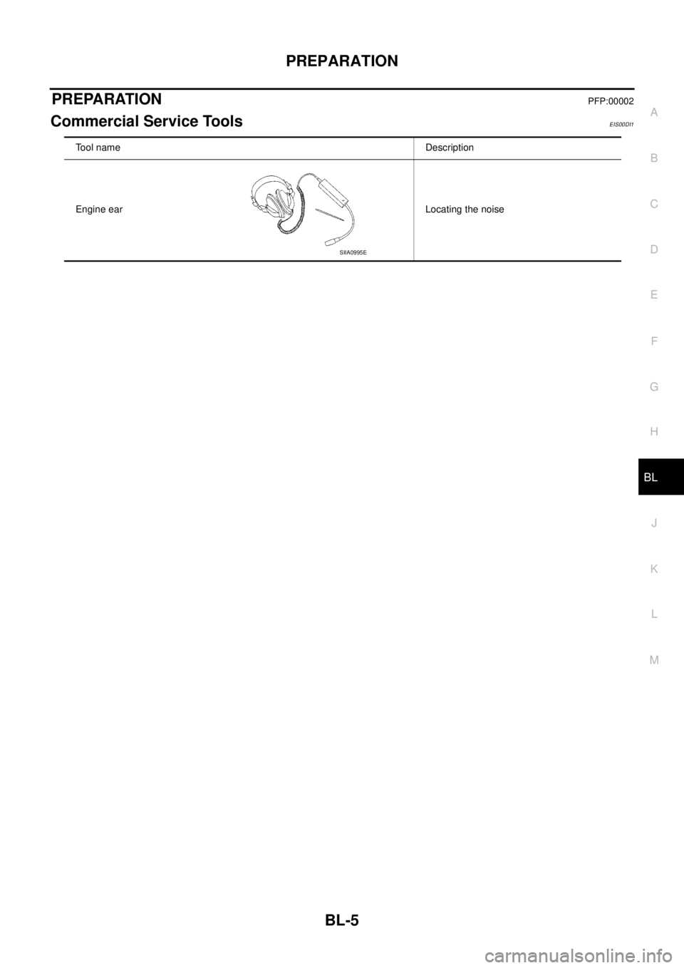
Engine ear Locating the noise
SIIA0995E
Page 591 of 3171

SQUEAK AND RATTLE TROUBLE DIAGNOSES
BL-7
C
D
E
F
G
H
J
K
L
MA
B
BL
DUPLICATE THE NOISE AND TEST DRIVE
If possible, drive the vehicle with the customer until the noise is duplicated. Note any additional information on
the Diagnostic Worksheet regarding the conditions or location of the noise. This information can be used to
duplicate the same conditions when you confirm the repair.
If the noise can be duplicated easily during the test drive, to help identify the source of the noise, try to dupli-
cate the noise with the vehicle stopped by doing one or all of the following:
1) Close a door.
2) Tap or push/pull around the area where the noise appears to be coming from.
3) Rev the engine.
4) Use a floor jack to recreate vehicle “twist”.
5) At idle, apply engine load (electrical load, half-clutch on M/T models, drive position on A/T models).
6) Raisethevehicleonahoistandhitatirewitharubberhammer.
lDrive the vehicle and attempt to duplicate the conditions the customer states exist when the noise occurs.
lIf it is difficult to duplicate the noise, drive the vehicle slowly on an undulating or rough road to stress the
vehicle body.
CHECK RELATED SERVICE BULLETINS
After verifying the customer concern or symptom, check ASIST for Technical Service Bulletins (TSBs) related
to that concern or symptom.
If a TSB relates to the symptom, follow the procedure to repair the noise.
LOCATE THE NOISE AND IDENTIFY THE ROOT CAUSE
1. Narrow down the noise to a general area. To help pinpoint the source of the noise, use a listening tool
(Engine Ear or mechanics stethoscope).
2. Narrow down the noise to a more specific area and identify the cause of the noise by:
lremoving the components in the area that you suspect the noise is coming from.
Do not use too much force when removing clips and fasteners, otherwise clips and fastener can be broken
or lost during the repair, resulting in the creation of new noise.
ltapping or pushing/pulling the component that you suspect is causing the noise.
Do not tap or push/pull the component with excessive force, otherwise the noise will be eliminated only
temporarily.
lfeeling for a vibration with your hand by touching the component(s) that you suspect is (are) causing the
noise.
lplacing a piece of paper between components that you suspect are causing the noise.
llooking for loose components and contact marks.
Refer toBL-8, "
Generic Squeak and Rattle Troubleshooting".
REPAIR THE CAUSE
lIf the cause is a loose component, tighten the component securely.
lIf the cause is insufficient clearance between components:
–separate components by repositioning or loosening and retightening the component, if possible.
–insulate components with a suitable insulator such as urethane pads, foam blocks, felt cloth tape or ure-
thane tape are available through your authorized Nissan Parts Department.
CAUTION:
Do not use excessive force as many components are constructed of plastic and may be damaged.
NOTE:
Always check with the Parts Department for the latest parts information.
Each item can be ordered separately as needed.
URETHANE PADS [1.5 mm (0.059 in) thick]
Insulates connectors, harness, etc.
76268-9E005: 100´135 mm (3.94´5.31 in)/76884-71L01: 60´85 mm (2.36´3.35 in)/76884-71L02: 15´
25 mm (0.59´0.98 in)
INSULATOR (Foam blocks)
Insulates components from contact. Can be used to fill space behind a panel.
73982-9E000: 45 mm (1.77 in) thick, 50´50 mm (1.97´1.97 in)/73982-50Y00: 10 mm (0.39 in) thick, 50
´50 mm (1.97´1.97 in)
INSULATOR (Light foam block)
80845-71L00: 30 mm (1.18 in) thick, 30´50 mm (1.18´1.97 in)
Page 593 of 3171

SQUEAK AND RATTLE TROUBLE DIAGNOSES
BL-9
C
D
E
F
G
H
J
K
L
MA
B
BL
TRUNK
Trunk noises are often caused by a loose jack or loose items put into the trunk by the owner.
In addition look for:
1. Trunk lid dumpers out of adjustment
2. Trunk lid striker out of adjustment
3. Trunk lid torsion bars knocking together
4. A loose license plate or bracket
Most of these incidents can be repaired by adjusting, securing or insulating the item(s) or component(s) caus-
ing the noise.
SUNROOF/HEADLINING
Noises in the sunroof/headlining area can often be traced to one of the following:
1. Sunroof lid, rail, linkage or seals making a rattle or light knocking noise
2. Sunvisor shaft shaking in the holder
3. Front or rear windshield touching headlining and squeaking
Again, pressing on the components to stop the noise while duplicating the conditions can isolate most of these
incidents. Repairs usually consist of insulating with felt cloth tape.
SEATS
When isolating seat noise it's important to note the position the seat is in and the load placed on the seat when
the noise is present. These conditions should be duplicated when verifying and isolating the cause of the
noise.
Cause of seat noise include:
1. Headrest rods and holder
2. A squeak between the seat pad cushion and frame
3. Rear seatback lock and bracket
These noises can be isolated by moving or pressing on the suspected components while duplicating the con-
ditions under which the noise occurs. Most of these incidents can be repaired by repositioning the component
or applying urethane tape to the contact area.
UNDERHOOD
Some interior noise may be caused by components under the hood or on the engine wall. The noise is then
transmitted into the passenger compartment.
Causes of transmitted underhood noise include:
1. Any component mounted to the engine wall
2. Components that pass through the engine wall
3. Engine wall mounts and connectors
4. Loose radiator mounting pins
5. Hood bumpers out of adjustment
6. Hood striker out of adjustment
These noises can be difficult to isolate since they cannot be reached from the interior of the vehicle. The best
method is to secure, move or insulate one component at a time and test drive the vehicle. Also, engine RPM
or load can be changed to isolate the noise. Repairs can usually be made by moving, adjusting, securing, or
insulating the component causing the noise.
Page 600 of 3171

BL-16
HOOD
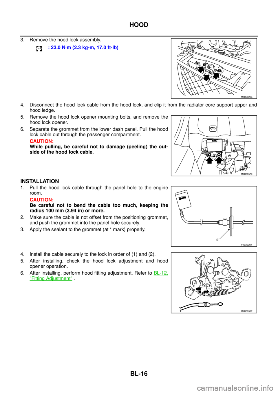
3. Remove the hood lock assembly.
4. Disconnect the hood lock cable from the hood lock, and clip it from the radiator core support upper and
hood ledge.
5. Remove the hood lock opener mounting bolts, and remove the
hood lock opener.
6. Separate the grommet from the lower dash panel. Pull the hood
lock cable out through the passenger compartment.
CAUTION:
While pulling, be careful not to damage (peeling) the out-
side of the hood lock cable.
INSTALLATION
1. Pull the hood lock cable through the panel hole to the engine
room.
CAUTION:
Be careful not to bend the cable too much, keeping the
radius 100 mm (3.94 in) or more.
2. Make sure the cable is not offset from the positioning grommet,
and push the grommet into the panel hole securely.
3. Apply the sealant to the grommet (at * mark) properly.
4. Install the cable securely to the lock in order of (1) and (2).
5. After installing, check the hood lock adjustment and hood
opener operation.
6. After installing, perform hood fitting adjustment. Refer toBL-12,
"Fitting Adjustment". : 23.0 N·m (2.3 kg-m, 17.0 ft-lb)
MIIB0629E
MIIB0657E
PIIB2909J
MIIB0638E
Page 602 of 3171

BL-18
RADIATOR CORE SUPPORT
RADIATOR CORE SUPPORT
PFP:62500
Removal and InstallationEIS00DGJ
REMOVAL
1. Remove the hood assembly. Refer toBL-14, "Removal and Installation of Hood Assembly".
2. Remove the front grille. Refer toEI-19, "
FRONT GRILLE".
3. Remove the front bumper, bumper reinforcement and bumper bracket. Refer toEI-15, "
FRONT BUMPER"
.
4. Remove the headlamp assembly (LH/RH). Refer toLT-30, "
Removal and Installation".
5. Remove the air intake duct (Air guide). Refer toEM-15, "
AIR CLEANER AND AIR DUCT".
6. Remove the charge air cooler. (for YD25 engine models only) Refer toEM-18, "
CHARGE AIR COOLER".
7. Remove the power steering oil cooler. Refer toPS-30, "
HYDRAULIC LINE".
8. Remove the A/T fluid cooler and A/T fluid cooler tube mounting nuts. Refer toAT- 2 4 4 , "
A/T FLUID
COOLER".
9. Remove the hood lock assembly, and then remove the hood lock cable. Refer toBL-15, "
Removal and
Installation of Hood Lock Control".
10. Remove the horn harness connector.
11. Disconnect the ambient sensor connector and remove the ambient sensor. Refer toAT C - 11 7 , "
Removal
and Installation".
12. Remove the mounting harness clip on radiator core support assembly, the harness is separate.
13. Remove the upper radiator bracket. Refer toCO-11, "
RADIATOR".
1. Radiator core support assembly 2. Air intake duct (Air guide) RH 3. Air intake duct (Air guide) LH
4. Horn (Low) 5. Headlamp lower bracket RH 6. Headlamp lower bracket LH
7. Headlamp side bracket RH 8. Headlamp side bracket LH
MIIB0979E
Page 724 of 3171

BL-140
THEFT WARNING SYSTEM
System Description
EIS00DBX
DESCRIPTION
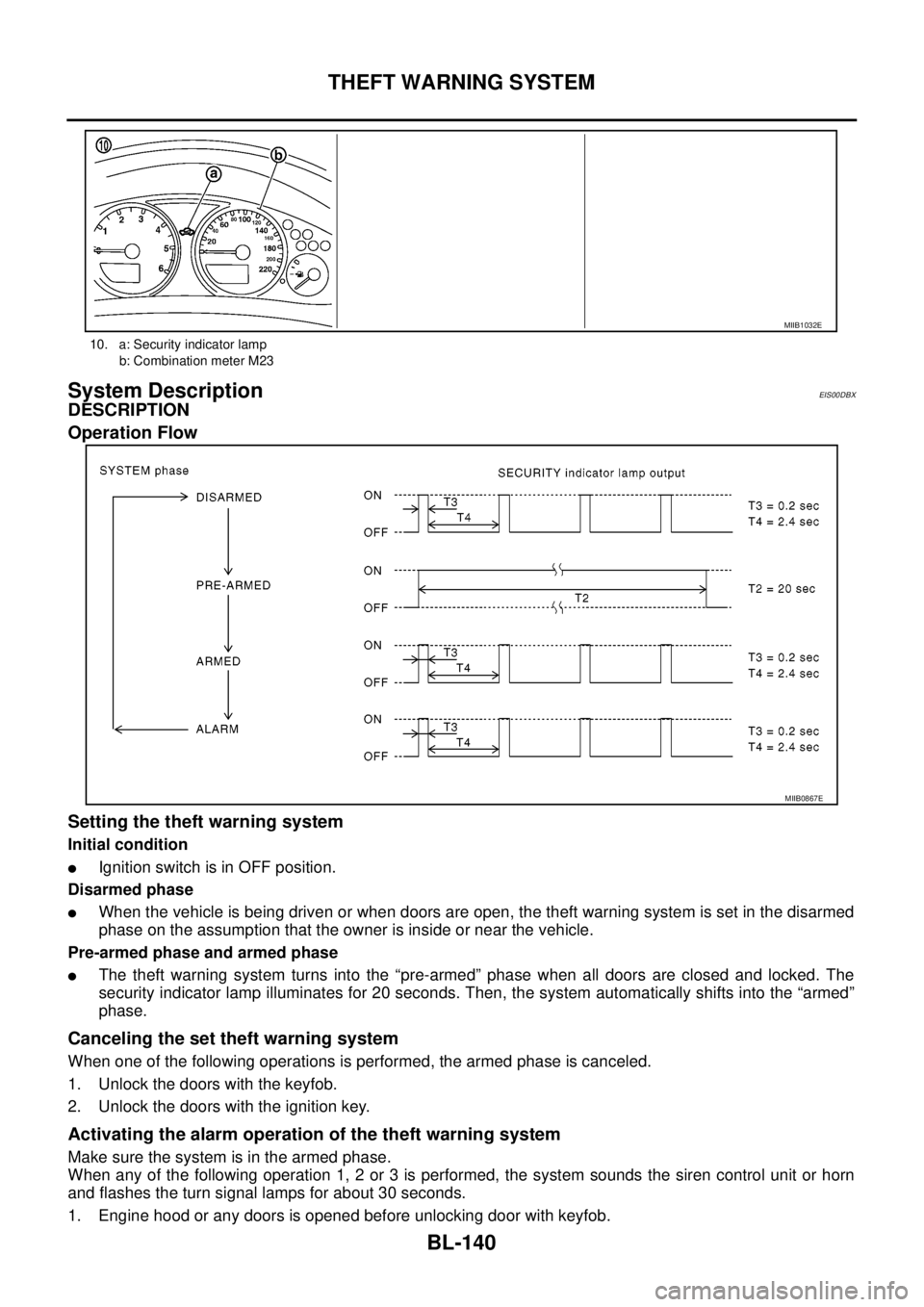
Operation Flow
Setting the theft warning system
Initial condition
lIgnition switch is in OFF position.
Disarmed phase
lWhen the vehicle is being driven or when doors are open, the theft warning system is set in the disarmed
phase on the assumption that the owner is inside or near the vehicle.
Pre-armed phase and armed phase
lThe theft warning system turns into the “pre-armed” phase when all doors are closed and locked. The
security indicator lamp illuminates for 20 seconds. Then, the system automatically shifts into the “armed”
phase.
Canceling the set theft warning system
When one of the following operations is performed, the armed phase is canceled.
1. Unlock the doors with the keyfob.
2. Unlock the doors with the ignition key.
Activating the alarm operation of the theft warning system
Make sure the system is in the armed phase.
When any of the following operation 1, 2 or 3 is performed, the system sounds the siren control unit or horn
and flashes the turn signal lamps for about 30 seconds.
1. Engine hood or any doors is opened before unlocking door with keyfob.
10. a: Security indicator lamp
b: Combination meter M23
MIIB1032E
MIIB0867E
Page 725 of 3171

THEFT WARNING SYSTEM
BL-141
C
D
E
F
G
H
J
K
L
MA
B
BL
2. A door is unlocked without using the keyfob.
3. Disconnect and connecting the battery connector before canceling armed phase.
POWER SUPPLY AND GROUND CIRCUIT
Power is supplied at all times
lthrough 10A fuse [No.19, located in the fuse block (J/B)]
lto combination meter (security indicator lamp) terminal 3
lthrough 50A fusible link (letterG, located in the fuse and fusible link box)
lto BCM terminal 57
lthrough 10A fuse [No. 21, located in the fuse block (J/B)]
lto BCM terminal 41
lthrough 15A fuse (No. 30, located in the fuse and fusible link box)
lto horn relay terminal 2
lthrough 20A fuse (No. 52, located in the IPDM E/R)
lthrough 20A fuse (No. 53, located in the IPDM E/R),
lto IPDM E/R internal CPU.
With the ignition switch in the ACC or ON position, power is supplied
lthrough 10A fuse [No. 4, located in the fuse block (J/B)]
lto BCM terminal 4.
Ground is supplied
lto BCM terminal 55
lthrough body grounds M21, M80 and M83
lto IPDM E/R terminals 38 and 59
lthrough body ground E21, E41 and E61.
INITIAL CONDITION TO ACTIVATE THE SYSTEM
The operation of the theft warning system is controlled by the engine hood and doors.
To activate the theft warning system, BCM must receive signals indicating the doors are closed and locked.
When a door is open, BCM terminal 12, 14, 15 or 16 receives a ground signal from each door switch.
When the engine hood is open, IPDM E/R terminal 41 receives a ground signal
THEFT WARNING SYSTEM ALARM OPERATION
The vehicle security system is triggered by
lopening a door
lopening the hood
ldetecting battery disconnect/connection.
The vehicle security system will be triggered once the system is in armed phase,
when BCM receives a ground signal at terminals 12, 14, 15, 16 (door switch) or IPDM E/R receives a ground
signal at terminal 41 (hood switch).
When the vehicle security system is triggered, siren control unit or horn is activate.
The alarm automatically turns off after 30 seconds, but will reactivate if the vehicle is tampered with again.
THEFT WARNING SYSTEM DEACTIVATION
To deactivate the theft warning system, a door must be unlocked with keyfob.
When the BCM receives either one of these signals or unlock signal from keyfob the theft warning system is
deactivated. (Disarmed phase)
CAN Communication System DescriptionEIS00DBY
Refer toLAN-23, "CAN COMMUNICATION".