Page 765 of 3171

NATS(NISSAN ANTI-THEFT SYSTEM)
BL-181
C
D
E
F
G
H
J
K
L
MA
B
BL
Diagnostic Procedure 2EIS00DB2
Self-diagnostic results:
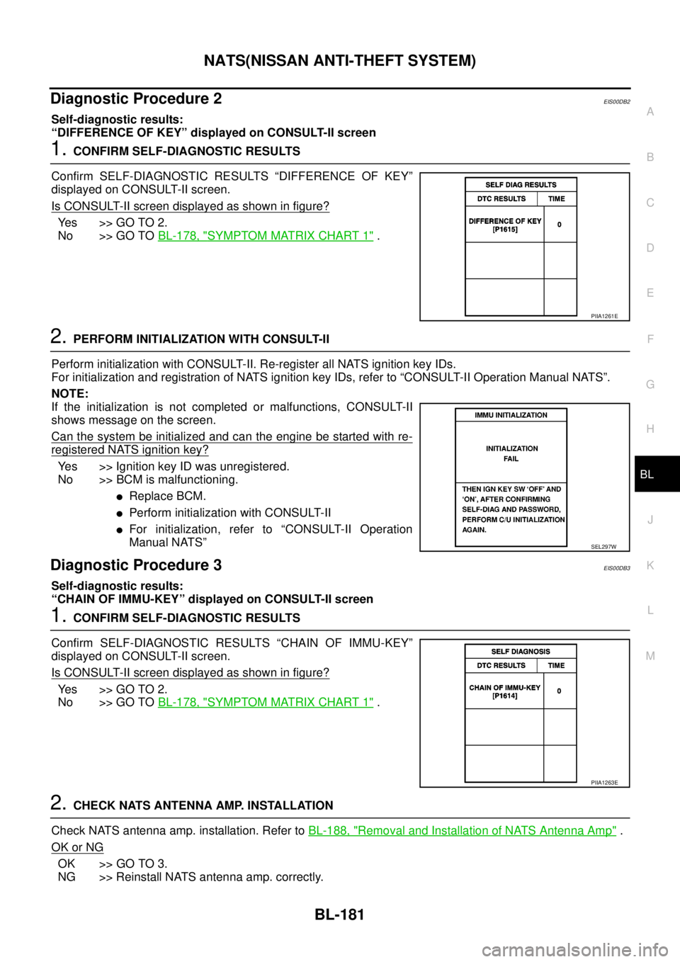
“DIFFERENCE OF KEY” displayed on CONSULT-II screen
1.CONFIRM SELF-DIAGNOSTIC RESULTS
Confirm SELF-DIAGNOSTIC RESULTS “DIFFERENCE OF KEY”
displayed on CONSULT-II screen.
Is CONSULT-II screen displayed as shown in figure?
Ye s > > G O T O 2 .
No >> GO TOBL-178, "
SYMPTOM MATRIX CHART 1".
2.PERFORM INITIALIZATION WITH CONSULT-II
Perform initialization with CONSULT-II. Re-register all NATS ignition key IDs.
For initialization and registration of NATS ignition key IDs, refer to “CONSULT-II Operation Manual NATS”.
NOTE:
If the initialization is not completed or malfunctions, CONSULT-II
shows message on the screen.
Can the system be initialized and can the engine be started with re-
registered NATS ignition key?
Yes >> Ignition key ID was unregistered.
No >> BCM is malfunctioning.
lReplace BCM.
lPerform initialization with CONSULT-II
lFor initialization, refer to “CONSULT-II Operation
Manual NATS”
Diagnostic Procedure 3EIS00DB3
Self-diagnostic results:
“CHAIN OF IMMU-KEY” displayed on CONSULT-II screen
1.CONFIRM SELF-DIAGNOSTIC RESULTS
Confirm SELF-DIAGNOSTIC RESULTS “CHAIN OF IMMU-KEY”
displayed on CONSULT-II screen.
Is CONSULT-II screen displayed as shown in figure?
Ye s > > G O T O 2 .
No >> GO TOBL-178, "
SYMPTOM MATRIX CHART 1".
2.CHECK NATS ANTENNA AMP. INSTALLATION
Check NATS antenna amp. installation. Refer toBL-188, "
Removal and Installation of NATS Antenna Amp".
OK or NG
OK >> GO TO 3.
NG >> Reinstall NATS antenna amp. correctly.
PIIA1261E
SEL297W
PIIA1263E
Page 766 of 3171

BL-182
NATS(NISSAN ANTI-THEFT SYSTEM)
3.CHECK NATS IGNITION KEY ID CHIP
Start engine with another registered NATS ignition key.
Doestheenginestart?
Yes >> Ignition key ID chip is malfunctioning.
lReplace the ignition key
lPerform initialization with CONSULT-II
For initialization, refer to “CONSULT-II Operation Manual NATS”
No >> GO TO 4.
4.CHECK POWER SUPPLY FOR NATS ANTENNA AMP.
1. Turn ignition switch “OFF”.
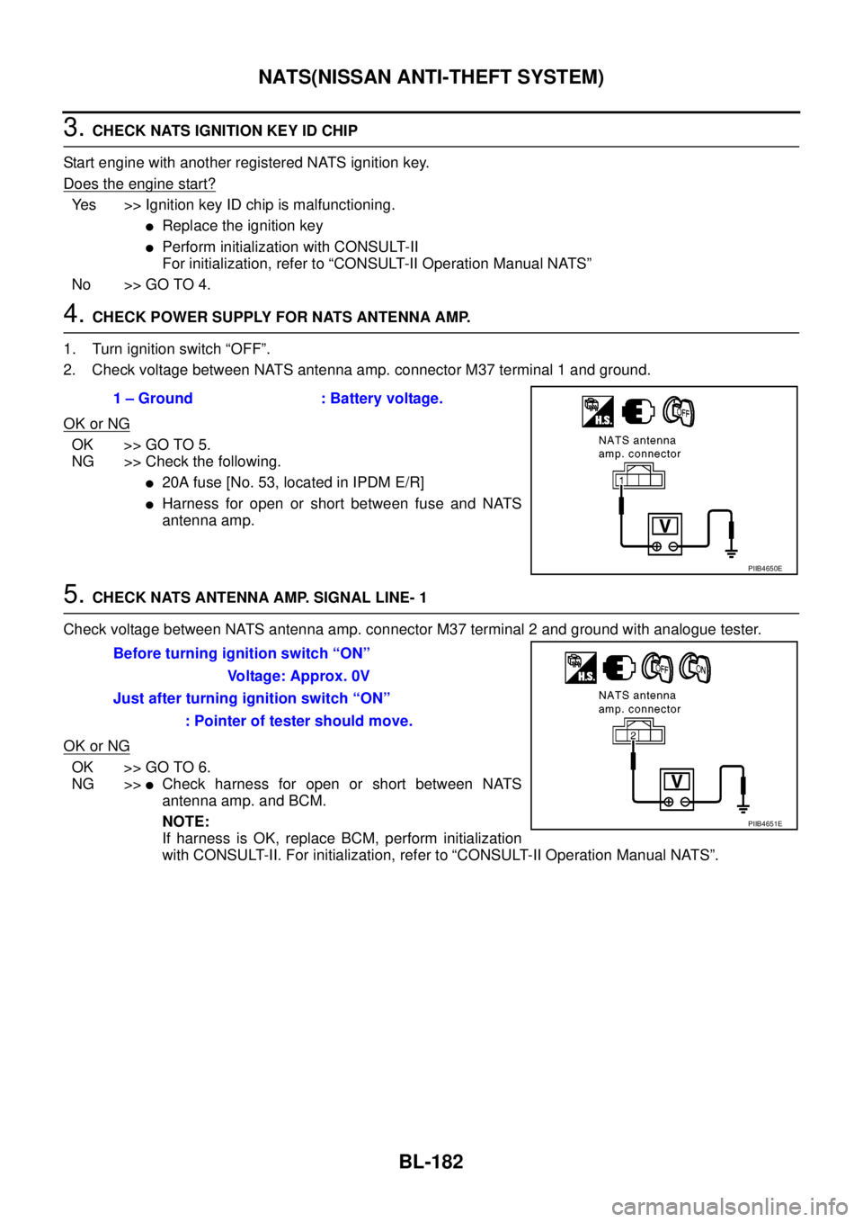
2. Check voltage between NATS antenna amp. connector M37 terminal 1 and ground.
OK or NG
OK >> GO TO 5.
NG >> Check the following.
l20A fuse [No. 53, located in IPDM E/R]
lHarness for open or short between fuse and NATS
antenna amp.
5.CHECK NATS ANTENNA AMP. SIGNAL LINE- 1
Check voltage between NATS antenna amp. connector M37 terminal 2 and ground with analogue tester.
OK or NG
OK >> GO TO 6.
NG >>
lCheck harness for open or short between NATS
antenna amp. and BCM.
NOTE:
If harness is OK, replace BCM, perform initialization
with CONSULT-II. For initialization, refer to “CONSULT-II Operation Manual NATS”. 1 – Ground : Battery voltage.
PIIB4650E
Before turning ignition switch “ON”
Voltage: Approx. 0V
Just after turning ignition switch “ON”
: Pointer of tester should move.
PIIB4651E
Page 768 of 3171

BL-184
NATS(NISSAN ANTI-THEFT SYSTEM)
Diagnostic Procedure 4
EIS00DB4
Self-diagnostic results:
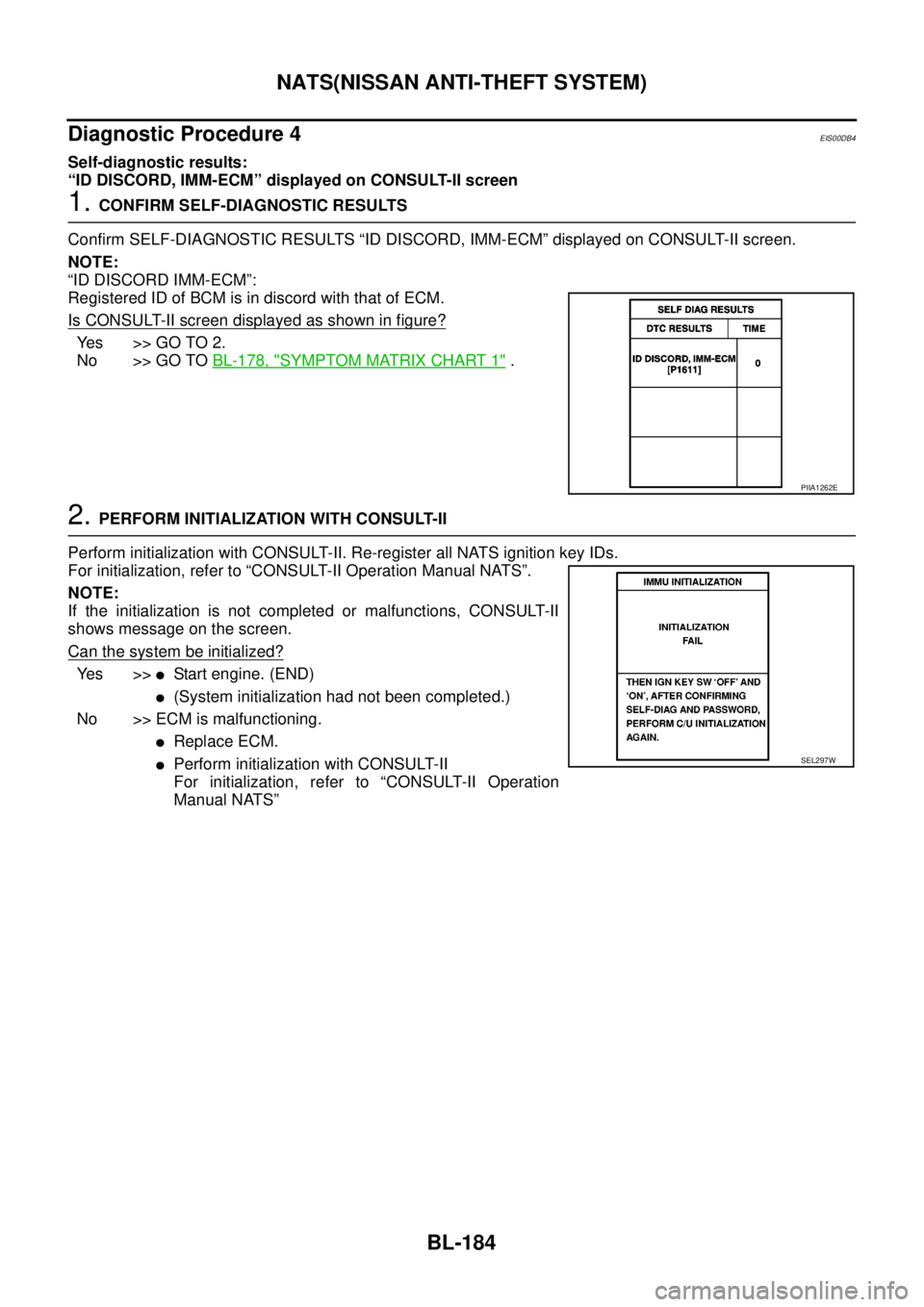
“ID DISCORD, IMM-ECM” displayed on CONSULT-II screen
1.CONFIRM SELF-DIAGNOSTIC RESULTS
Confirm SELF-DIAGNOSTIC RESULTS “ID DISCORD, IMM-ECM” displayed on CONSULT-II screen.
NOTE:
“ID DISCORD IMM-ECM”:
Registered ID of BCM is in discord with that of ECM.
Is CONSULT-II screen displayed as shown in figure?
Yes >>GOTO2.
No >> GO TOBL-178, "
SYMPTOM MATRIX CHART 1".
2.PERFORM INITIALIZATION WITH CONSULT-II
Perform initialization with CONSULT-II. Re-register all NATS ignition key IDs.
For initialization, refer to “CONSULT-II Operation Manual NATS”.
NOTE:
If the initialization is not completed or malfunctions, CONSULT-II
shows message on the screen.
Can the system be initialized?
Ye s > >lStart engine. (END)
l(System initialization had not been completed.)
No >> ECM is malfunctioning.
lReplace ECM.
lPerform initialization with CONSULT-II
For initialization, refer to “CONSULT-II Operation
Manual NATS”
PIIA1262E
SEL297W
Page 771 of 3171

NATS(NISSAN ANTI-THEFT SYSTEM)
BL-187
C
D
E
F
G
H
J
K
L
MA
B
BL
Diagnostic Procedure 6EIS00DB6
Self-diagnostic results:
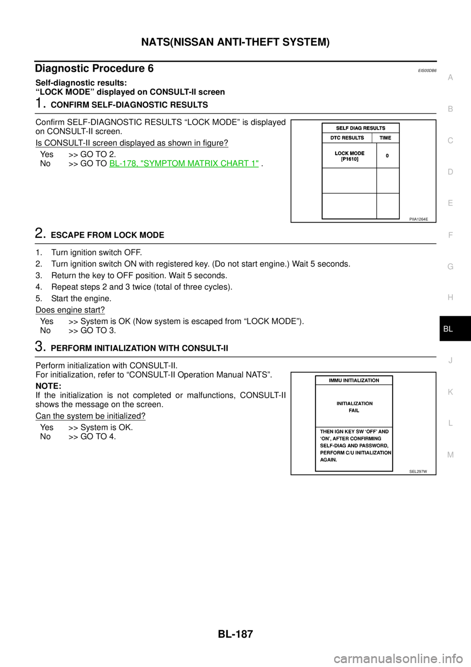
“LOCK MODE” displayed on CONSULT-II screen
1.CONFIRM SELF-DIAGNOSTIC RESULTS
Confirm SELF-DIAGNOSTIC RESULTS “LOCK MODE” is displayed
on CONSULT-II screen.
Is CONSULT-II screen displayed as shown in figure?
Ye s > > G O T O 2 .
No >> GO TOBL-178, "
SYMPTOM MATRIX CHART 1".
2.ESCAPE FROM LOCK MODE
1. Turn ignition switch OFF.
2. Turn ignition switch ON with registered key. (Do not start engine.) Wait 5 seconds.
3. Return the key to OFF position. Wait 5 seconds.
4. Repeat steps 2 and 3 twice (total of three cycles).
5. Start the engine.
Does engine start?
Yes >>SystemisOK(Nowsystemisescapedfrom“LOCKMODE”).
No >> GO TO 3.
3.PERFORM INITIALIZATION WITH CONSULT-II
Perform initialization with CONSULT-II.
For initialization, refer to “CONSULT-II Operation Manual NATS”.
NOTE:
If the initialization is not completed or malfunctions, CONSULT-II
shows the message on the screen.
Can the system be initialized?
Yes >>SystemisOK.
No >> GO TO 4.
PIIA1264E
SEL297W
Page 776 of 3171
BL-192
BODY REPAIR
ENGINE COMPARTMENT
Measurement
LIIA1792E
Page 792 of 3171
BR-6
BRAKE PEDAL
BRAKE PEDAL
PFP:46501
Inspection and AdjustmentEFS005SG
Play and clearance inspection between brake pedal and floor panel with pedal depressed.
lCheck brake pedal play.
lCheck brake pedal height from dash lower panel (1).
lAdjust height referring to the following specifications.
SFIA2743J
H1Brake pedal height
(From dash lower panel top surface)LHD
modelA/T182.1-192.1 mm
(7.17-7.56 in)
M/T174.7-184.7 mm
(6.88-7.27 in)
RHD
modelA/T171.2-181.2 mm
(6.74-7.13 in)
M/T164.1-174.1 mm
(6.46-6.85 in)
H
2
Brake pedal depressed height
[Under a force of 490 N (50 kg, 110 lb) with engine
running]LHD model 120 mm (4.72 in) or more
RHD model 110 mm (4.33 in) or more
CClearance between bracket (3) and threaded end of the stop lamp
switch (2)0.74-1.96 mm
(0.0291-0.0772 in)
A Pedal play3-11 m m
(0.12-0.43 in)
Page 793 of 3171
BRAKE PEDAL
BR-7
C
D
E
G
H
I
J
K
L
MA
B
BR
ADJUSTMENT
1. Loosen the stop lamp switch and by turning it counterclockwise
by 45°.
2. Loosen lock nut (A) on the input rod, then turn input rod to adjust
the pedal to specified height, and tighten lock nut (A).
CAUTION:
Make sure the threaded end of the input rod stays inside the
clevis.
3. With the pedal pulled and held by hand, press the stop lamp
switch and until its threaded end contacts the stopper.
4. With the threaded end of the stop lamp switch and contacting
the stopper, turn the switch clockwise by 45°to secure.
CAUTION:
Make sure that the clearance (C) between the bracket and
threaded end of the stop lamp switch and are within the
standard.
5. Check the pedal play.
CAUTION:
Make sure that the stop lamp goes off when the pedal is
released.
6. Start the engine to check the brake pedal depressed height.
Refer toBR-6, "
Inspection and Adjustment". Lock nut (A)
:18.7 N·m (1.9 kg-m, 14 ft-lb)
PFIA0436E
Page 800 of 3171
BR-14
BRAKE TUBE AND HOSE
Inspection after Installation
EFS005SO
CAUTION:
Brake tubes and hoses are important safety parts. Always disassemble the parts and retighten their fit-
tings, if a brake fluid leak is detected. Replace applicable part with a new one, if damaged part is
detected.
1. Check hydraulic brake lines (tubes and hoses) and connections for fluid leakage, damage, twists, defor-
mations, contacts with other parts, and loose connections. Replace any damage parts.
2. While depressing brake pedal under a force of 785 N (80 kg, 177 lb) with engine running at idle speed for
approximately 5 seconds, check each part for fluid leakage.