2005 NISSAN NAVARA engine
[x] Cancel search: enginePage 415 of 3171
TROUBLE DIAGNOSIS
ATC-81
C
D
E
F
G
H
I
K
L
MA
B
AT C
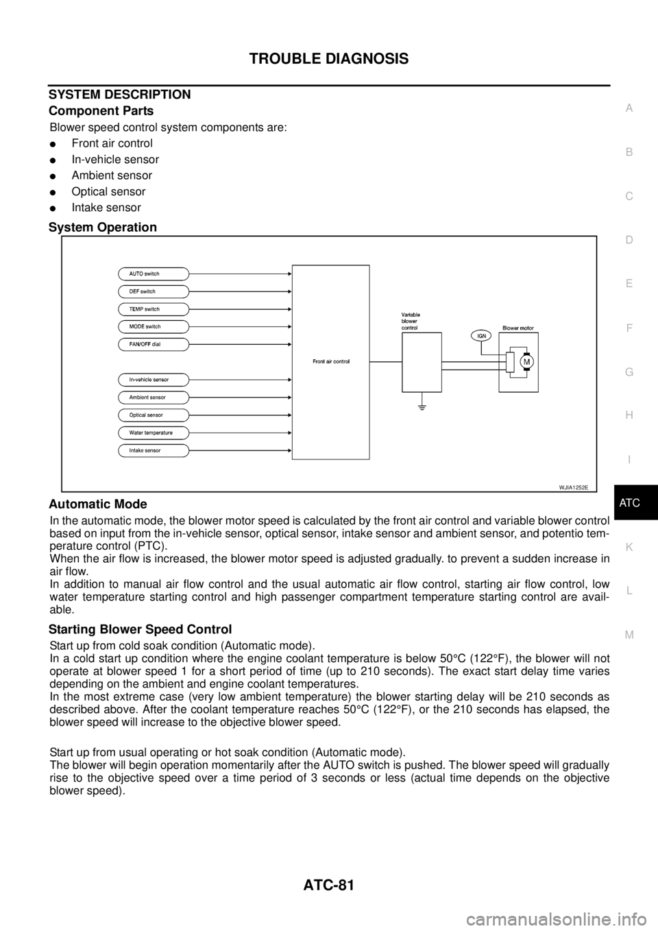
SYSTEM DESCRIPTION
Component Parts
Blower speed control system components are:
lFront air control
lIn-vehicle sensor
lAmbient sensor
lOptical sensor
lIntake sensor
System Operation
Automatic Mode
In the automatic mode, the blower motor speed is calculated by the front air control and variable blower control
based on input from the in-vehicle sensor, optical sensor, intake sensor and ambient sensor, and potentio tem-
perature control (PTC).
When the air flow is increased, the blower motor speed is adjusted gradually. to prevent a sudden increase in
air flow.
In addition to manual air flow control and the usual automatic air flow control, starting air flow control, low
water temperature starting control and high passenger compartment temperature starting control are avail-
able.
Starting Blower Speed Control
Start up from cold soak condition (Automatic mode).
In a cold start up condition where the engine coolant temperature is below 50°C(122°F), the blower will not
operate at blower speed 1 for a short period of time (up to 210 seconds). The exact start delay time varies
depending on the ambient and engine coolant temperatures.
In the most extreme case (very low ambient temperature) the blower starting delay will be 210 seconds as
described above. After the coolant temperature reaches 50°C(122°F), or the 210 seconds has elapsed, the
blower speed will increase to the objective blower speed.
Start up from usual operating or hot soak condition (Automatic mode).
The blower will begin operation momentarily after the AUTO switch is pushed. The blower speed will gradually
rise to the objective speed over a time period of 3 seconds or less (actual time depends on the objective
blower speed).
WJIA1252E
Page 425 of 3171
TROUBLE DIAGNOSIS
ATC-91
C
D
E
F
G
H
I
K
L
MA
B
AT C
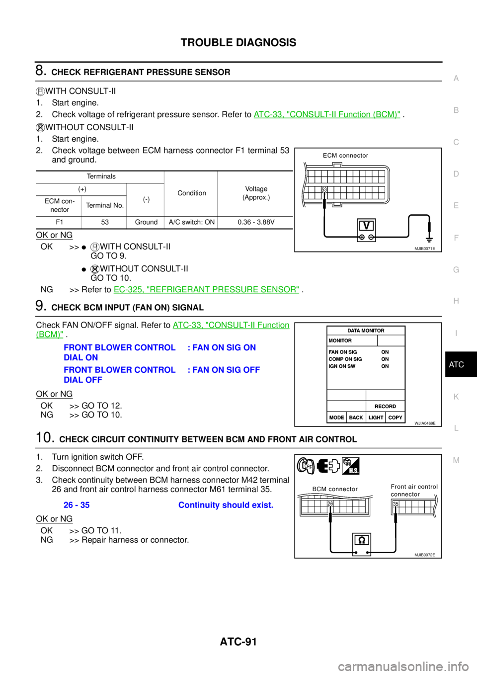
8.CHECK REFRIGERANT PRESSURE SENSOR
WITH CONSULT-II
1. Start engine.
2. Check voltage of refrigerant pressure sensor. Refer toAT C - 3 3 , "
CONSULT-II Function (BCM)".
WITHOUT CONSULT-II
1. Start engine.
2. Check voltage between ECM harness connector F1 terminal 53
and ground.
OK or NG
OK >>lWITH CONSULT-II
GO TO 9.
lWITHOUT CONSULT-II
GO TO 10.
NG >> Refer toEC-325, "
REFRIGERANT PRESSURE SENSOR".
9.CHECK BCM INPUT (FAN ON) SIGNAL
Check FAN ON/OFF signal. Refer toAT C - 3 3 , "
CONSULT-II Function
(BCM)".
OK or NG
OK >> GO TO 12.
NG >> GO TO 10.
10.CHECK CIRCUIT CONTINUITY BETWEEN BCM AND FRONT AIR CONTROL
1. Turn ignition switch OFF.
2. Disconnect BCM connector and front air control connector.
3. Check continuity between BCM harness connector M42 terminal
26 and front air control harness connector M61 terminal 35.
OK or NG
OK >> GO TO 11.
NG >> Repair harness or connector.
Te r m i n a l s
ConditionVo l ta g e
(Approx.) (+)
(-)
ECM con-
nectorTerminal No.
F1 53 Ground A/C switch: ON 0.36 - 3.88V
MJIB0071E
FRONT BLOWER CONTROL
DIAL ON: FAN ON SIG ON
FRONT BLOWER CONTROL
DIAL OFF:FANONSIGOFF
WJIA0469E
26 - 35 Continuity should exist.
MJIB0072E
Page 430 of 3171

ATC-96
TROUBLE DIAGNOSIS
PERFORMANCE CHART
Test Condition
Testing must be performed as follows:
Test Reading
Recirculating-to-discharge Air Temperature Table
Ambient Air Temperature-to-operating Pressure Table
Vehicle location Indoors or in the shade (in a well-ventilated place)
Doors Closed
Door window Open
Hood Open
TEMP. Max. COLD
Mode switch
(Ventilation) set
Recirculation (REC) switch
(Recirculation) set
Blower speedMax. speed set
Engine speed Idle speed
Operate the air conditioning system for 10 minutes before taking measurements.
Inside air (Recirculating air) at blower assembly inlet
Discharge air temperature at center ventilator
°C(°F) Relative humidity
%Air temperature
°C(°F)
40 - 6020 (68) 9.6 - 12.0 (49 - 54)
25 (77) 13.6 - 16.5 (56 - 62)
30 (86) 18.0 - 21.4 (64 - 71)
35 (95) 22.8 - 26.7 (73 - 80)
60 - 8020 (68) 12.0 - 14.3 (54 - 58)
25 (77) 16.5 - 19.3 (62 - 67)
30 (86) 21.4 - 24.8 (71 - 77)
35 (95) 26.7 - 30.5 (80 - 87)
Ambient air
High-pressure (Discharge side)
kPa (kg/cm
2, psi)Low-pressure (Suction side)
kPa (kg/cm2, psi) Relative humidity
%Air temperature
°C(°F)
40 - 6020 (68)1,090 - 1,210
(11.11 - 12.33, 158.0 - 175.4)220 - 240
(2.24 - 2.45, 31.9 - 34.8)
25 (77)1,370 - 1,520
(13.97 - 15.49, 198.6 - 220.3)280 - 310
(2.85 - 3.16, 40.6 - 44.9)
30 (86)1,610 - 1,790
(16.41 - 18.25, 233.4 - 259.5)330 - 370
(3.36 - 3.77, 47.8 - 53.6)
35 (95)1,940 - 2,150
(19.78 - 21.92, 281.2 - 311.7)390 - 430
(3.98 - 4.38, 56.5 - 62.3)
60 - 8020 (68)1,210 - 1,330
(12.33 - 13.56, 175.4 - 192.8)240 - 260
(2.45 - 2.65, 34.8 - 37.7)
25 (77)1,520 - 1,670
(15.49 - 17.02, 220.3 - 242.1)310 - 340
(3.16 - 3.47, 44.9 - 49.3)
30 (86)1,790 - 1,970
(18.25 - 20.08, 259.5 - 285.6)370 - 410
(3.77 - 4.18, 53.6 - 59.4)
35 (95)2,150 - 2,370
(21.92 - 24.16, 311.7 - 343.5)430 - 470
(4.38 - 4.79, 62.3 - 68.1)
Page 431 of 3171
TROUBLE DIAGNOSIS
ATC-97
C
D
E
F
G
H
I
K
L
MA
B
AT C
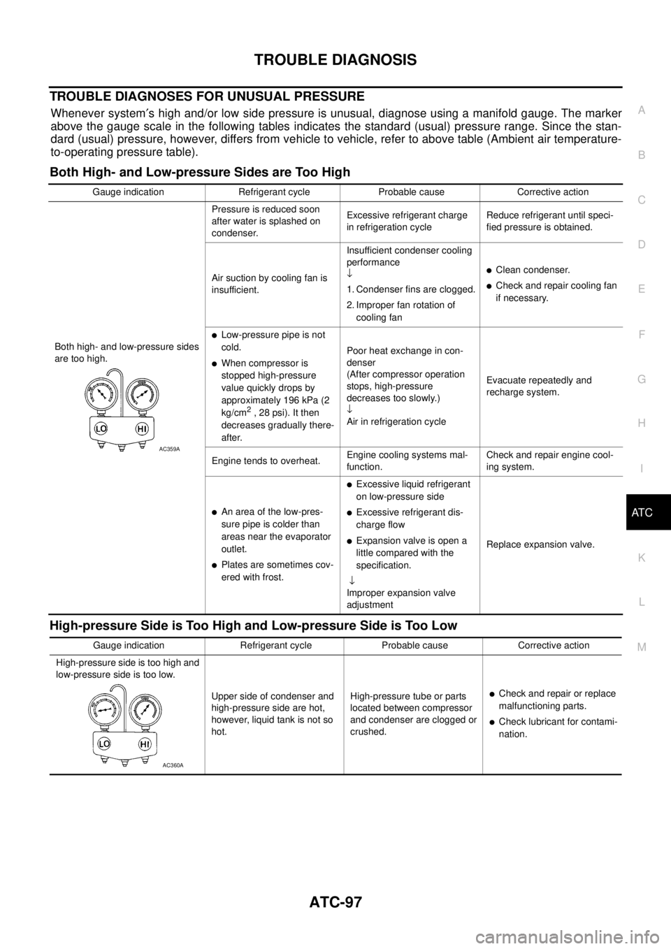
TROUBLE DIAGNOSES FOR UNUSUAL PRESSURE
Whenever system¢s high and/or low side pressure is unusual, diagnose using a manifold gauge. The marker
above the gauge scale in the following tables indicates the standard (usual) pressure range. Since the stan-
dard (usual) pressure, however, differs from vehicle to vehicle, refer to above table (Ambient air temperature-
to-operating pressure table).
Both High- and Low-pressure Sides are Too High
High-pressure Side is Too High and Low-pressure Side is Too Low
Gauge indication Refrigerant cycle Probable cause Corrective action
Both high- and low-pressure sides
are too high.Pressure is reduced soon
after water is splashed on
condenser.Excessive refrigerant charge
in refrigeration cycleReduce refrigerant until speci-
fied pressure is obtained.
Air suction by cooling fan is
insufficient.Insufficient condenser cooling
performance
¯
1. Condenser fins are clogged.
2. Improper fan rotation of
cooling fan
lClean condenser.
lCheck and repair cooling fan
if necessary.
lLow-pressure pipe is not
cold.
lWhen compressor is
stopped high-pressure
value quickly drops by
approximately 196 kPa (2
kg/cm
2, 28 psi). It then
decreases gradually there-
after.Poor heat exchange in con-
denser
(After compressor operation
stops, high-pressure
decreases too slowly.)
¯
Air in refrigeration cycleEvacuate repeatedly and
recharge system.
Engine tends to overheat.Engine cooling systems mal-
function.Check and repair engine cool-
ing system.
lAn area of the low-pres-
sure pipe is colder than
areas near the evaporator
outlet.
lPlates are sometimes cov-
ered with frost.
lExcessive liquid refrigerant
on low-pressure side
lExcessive refrigerant dis-
charge flow
lExpansion valve is open a
little compared with the
specification.
¯
Improper expansion valve
adjustmentReplace expansion valve.
AC359A
Gauge indication Refrigerant cycle Probable cause Corrective action
High-pressure side is too high and
low-pressure side is too low.
Upper side of condenser and
high-pressure side are hot,
however, liquid tank is not so
hot.High-pressure tube or parts
located between compressor
and condenser are clogged or
crushed.
lCheck and repair or replace
malfunctioning parts.
lCheck lubricant for contami-
nation.
AC360A
Page 434 of 3171
ATC-100
TROUBLE DIAGNOSIS
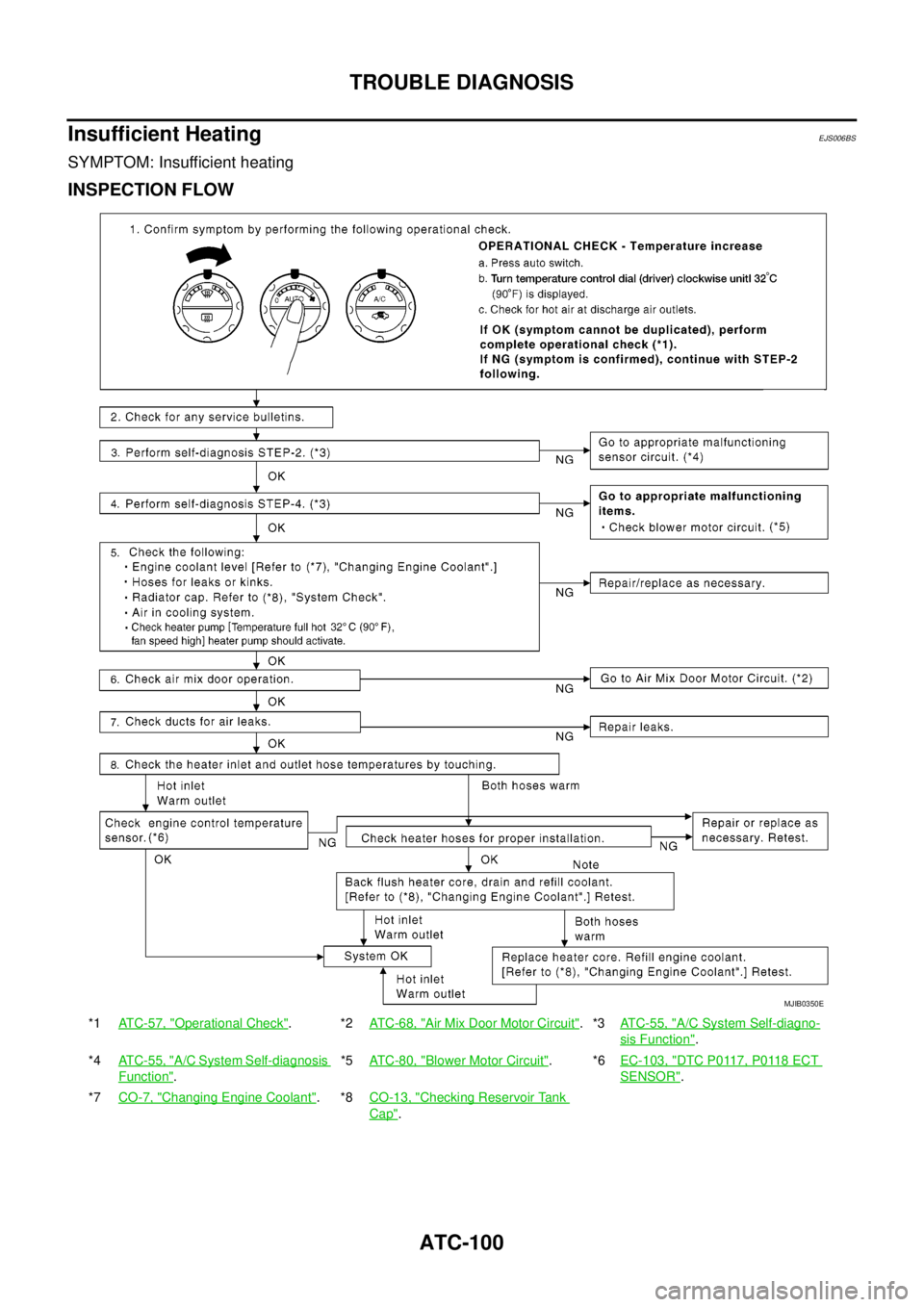
Insufficient Heating
EJS006BS
SYMPTOM: Insufficient heating
INSPECTION FLOW
*1ATC-57, "Operational Check".*2AT C - 6 8 , "Air Mix Door Motor Circuit".*3ATC-55, "A/C System Self-diagno-
sis Function".
*4ATC-55, "
A/C System Self-diagnosis
Function".*5AT C - 8 0 , "
Blower Motor Circuit".*6EC-103, "DTC P0117, P0118 ECT
SENSOR".
*7CO-7, "
Changing Engine Coolant".*8CO-13, "Checking Reservoir Tank
Cap".
MJIB0350E
Page 439 of 3171
TROUBLE DIAGNOSIS
ATC-105
C
D
E
F
G
H
I
K
L
MA
B
AT C
Ambient Sensor CircuitEJS006BW
COMPONENT DESCRIPTION
Ambient Sensor
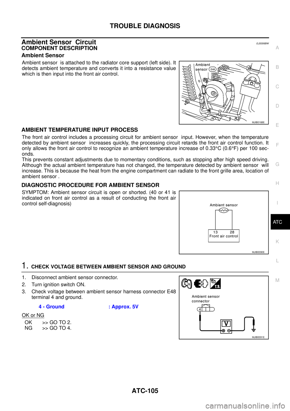
Ambient sensor is attached to the radiator core support (left side). It
detects ambient temperature and converts it into a resistance value
which is then input into the front air control.
AMBIENT TEMPERATURE INPUT PROCESS
The front air control includes a processing circuit for ambient sensor input. However, when the temperature
detected by ambient sensor increases quickly, the processing circuit retards the front air control function. It
only allows the front air control to recognize an ambient temperature increase of 0.33°C(0.6°F) per 100 sec-
onds.
This prevents constant adjustments due to momentary conditions, such as stopping after high speed driving.
Although the actual ambient temperature has not changed, the temperature detected by ambient sensor will
increase. This is because the heat from the engine compartment can radiate to the front grille area, location of
ambient sensor .
DIAGNOSTIC PROCEDURE FOR AMBIENT SENSOR
SYMPTOM: Ambient sensor circuit is open or shorted. (40 or 41 is
indicated on front air control as a result of conducting the front air
control self-diagnosis)
1.CHECK VOLTAGE BETWEEN AMBIENT SENSOR AND GROUND
1. Disconnect ambient sensor connector.
2. Turn ignition switch ON.
3. Check voltage between ambient sensor harness connector E48
terminal 4 and ground.
OK or NG
OK >> GO TO 2.
NG >> GO TO 4.
MJIB0168E
MJIB0090E
4 - Ground : Approx. 5V
MJIB0091E
Page 460 of 3171
ATC-126
HEATER & COOLING UNIT ASSEMBLY
Removal and Installation
EJS006C9
REMOVAL
1. Discharge the refrigerant from the A/C system. Refer toATC-138, "Discharging Refrigerant".
2. Drain the coolant from the engine cooling system. Refer toCO-8, "
DRAINING ENGINE COOLANT".
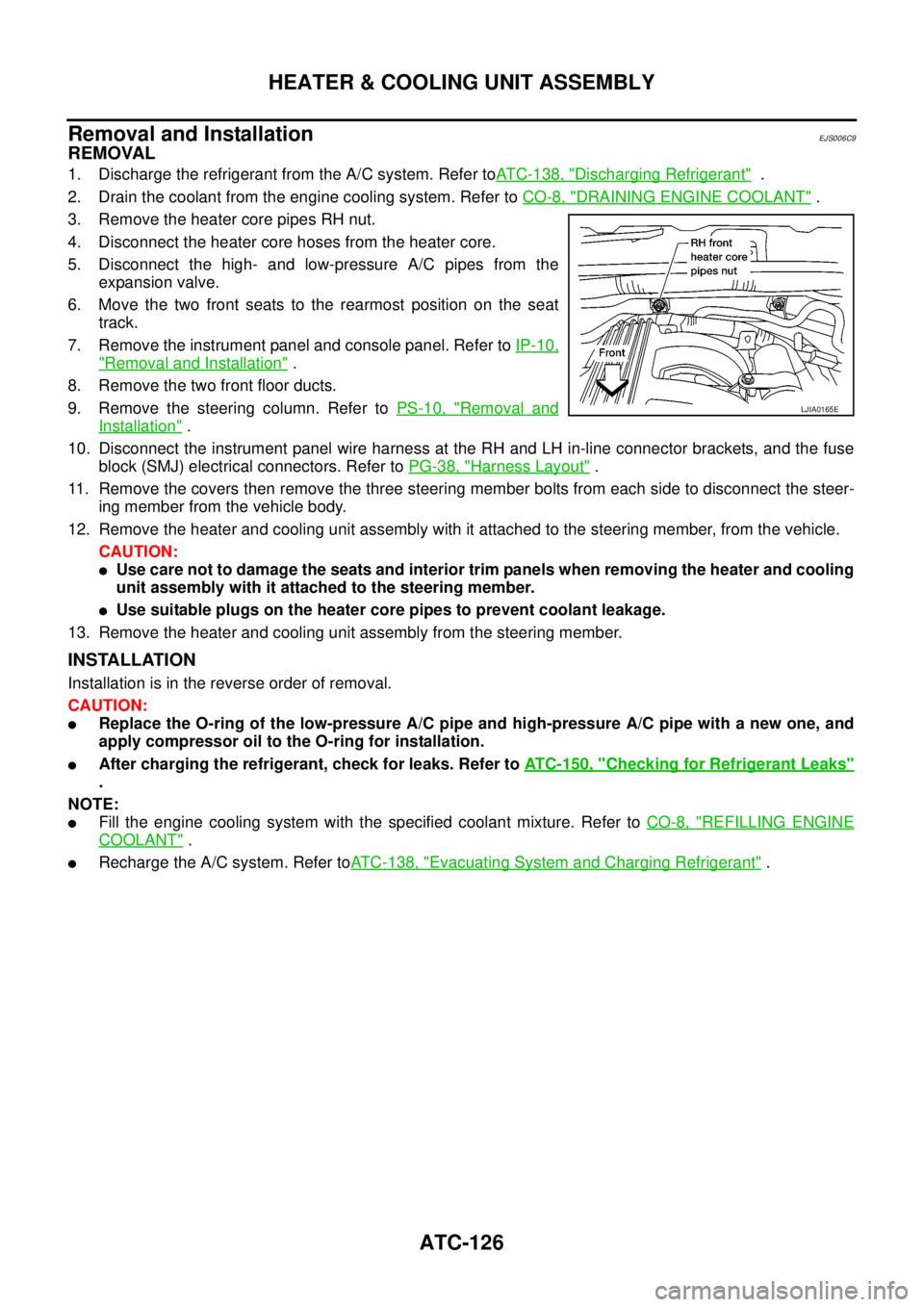
3. Remove the heater core pipes RH nut.
4. Disconnect the heater core hoses from the heater core.
5. Disconnect the high- and low-pressure A/C pipes from the
expansion valve.
6. Move the two front seats to the rearmost position on the seat
track.
7. Remove the instrument panel and console panel. Refer toIP-10,
"Removal and Installation".
8. Remove the two front floor ducts.
9. Remove the steering column. Refer toPS-10, "
Removal and
Installation".
10. Disconnect the instrument panel wire harness at the RH and LH in-line connector brackets, and the fuse
block (SMJ) electrical connectors. Refer toPG-38, "
Harness Layout".
11. Remove the covers then remove the three steering member bolts from each side to disconnect the steer-
ing member from the vehicle body.
12. Remove the heater and cooling unit assembly with it attached to the steering member, from the vehicle.
CAUTION:
lUse care not to damage the seats and interior trim panels when removing the heater and cooling
unit assembly with it attached to the steering member.
lUse suitable plugs on the heater core pipes to prevent coolant leakage.
13. Remove the heater and cooling unit assembly from the steering member.
INSTALLATION
Installation is in the reverse order of removal.
CAUTION:
lReplace the O-ring of the low-pressure A/C pipe and high-pressure A/C pipe with a new one, and
apply compressor oil to the O-ring for installation.
lAfter charging the refrigerant, check for leaks. Refer toATC-150, "Checking for Refrigerant Leaks"
.
NOTE:
lFill the engine cooling system with the specified coolant mixture. Refer toCO-8, "REFILLING ENGINE
COOLANT".
lRecharge the A/C system. Refer toATC-138, "Evacuating System and Charging Refrigerant".
LJIA0165E
Page 462 of 3171
ATC-128
HEATER PUMP
HEATER PUMP
PFP:92264
ComponentsEJS006CC
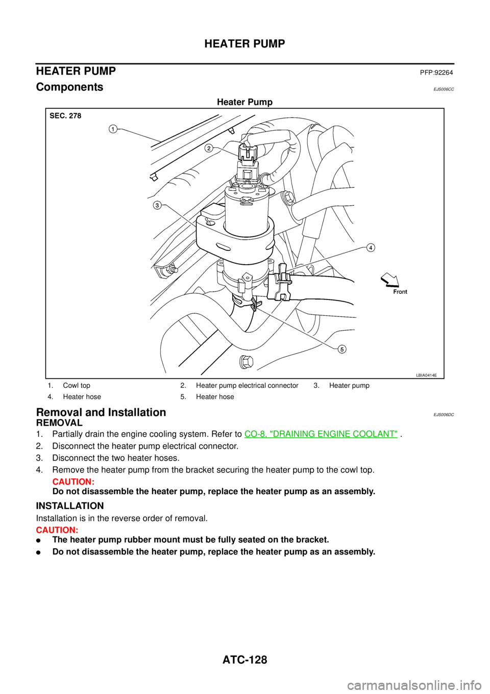
Heater Pump
Removal and InstallationEJS006DC
REMOVAL
1. Partially drain the engine cooling system. Refer toCO-8, "DRAINING ENGINE COOLANT".
2. Disconnect the heater pump electrical connector.
3. Disconnect the two heater hoses.
4. Remove the heater pump from the bracket securing the heater pump to the cowl top.
CAUTION:
Do not disassemble the heater pump, replace the heater pump as an assembly.
INSTALLATION
Installation is in the reverse order of removal.
CAUTION:
lThe heater pump rubber mount must be fully seated on the bracket.
lDo not disassemble the heater pump, replace the heater pump as an assembly.
LBIA0414E
1. Cowl top 2. Heater pump electrical connector 3. Heater pump
4. Heater hose 5. Heater hose