2005 NISSAN NAVARA engine
[x] Cancel search: enginePage 178 of 3171
AT-170
1ST POSITION SWITCH
1ST POSITION SWITCH
PFP:31918
CONSULT-II Reference ValueECS00I5W
Diagnostic ProcedureECS00I5X
1.CHECK CAN COMMUNICATION LINE
Perform the self-diagnosis. Refer toAT-80, "
SELF-DIAGNOSTIC RESULT MODE".
Is any malfunction in the CAN communication indicated in the results?
YES >> Check CAN communication line. Refer toAT-91, "DTC U1000 CAN COMMUNICATION LINE".
NO >> GO TO 2.
2.CHECK 1ST POSITION SWITCH CIRCUIT
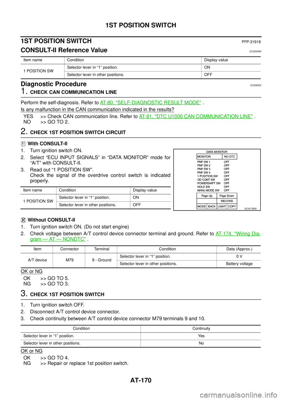
With CONSULT-II
1. Turn ignition switch ON.
2. Select “ECU INPUT SIGNALS” in “DATA MONITOR” mode for
“A/T” with CONSULT-II.
3. Read out “1 POSITION SW”.
Check the signal of the overdrive control switch is indicated
properly.
Without CONSULT-II
1. Turn ignition switch ON. (Do not start engine)
2. Check voltage between A/T control device connector terminal and ground. Refer toAT- 1 7 4 , "
Wiring Dia-
gram—AT—NONDTC".
OK or NG
OK >> GO TO 5.
NG >> GO TO 3.
3.CHECK 1ST POSITION SWITCH
1. Turn ignition switch OFF.
2. Disconnect A/T control device connector.
3. Check continuity between A/T control device connector M79 terminals 9 and 10.
OK or NG
OK >> GO TO 4.
NG >> Repair or replace 1st position switch.
Item name Condition Display value
1 POSITION SWSelector lever in “1” position. ON
Selector lever in other positions. OFF
Item name Condition Display value
1 POSITION SWSelector lever in “1” position. ON
Selector lever in other positions. OFF
SCIA7305E
Item Connector Terminal Condition Data (Approx.)
A/T device M79 9 - GroundSelector lever in “1” position. 0 V
Selector lever in other positions. Battery voltage
Condition Continuity
Selector lever in “1” position. Yes
Selector lever in other positions. No
Page 180 of 3171
AT-172
OVERDRIVE CONTROL SWITCH
OVERDRIVE CONTROL SWITCH
PFP:25130
CONSULT-II Reference ValueECS00HQY
Diagnostic ProcedureECS00HQZ
1.CHECK CAN COMMUNICATION LINE
Perform the self-diagnosis. Refer toAT-80, "
SELF-DIAGNOSTIC RESULT MODE".
Is any malfunction in the CAN communication indicated in the results?
YES >> Check CAN communication line. Refer toAT-91, "DTC U1000 CAN COMMUNICATION LINE".
NO >> GO TO 2.
2.CHECK OVERDRIVE CONTOROL SWITCH CIRCUIT
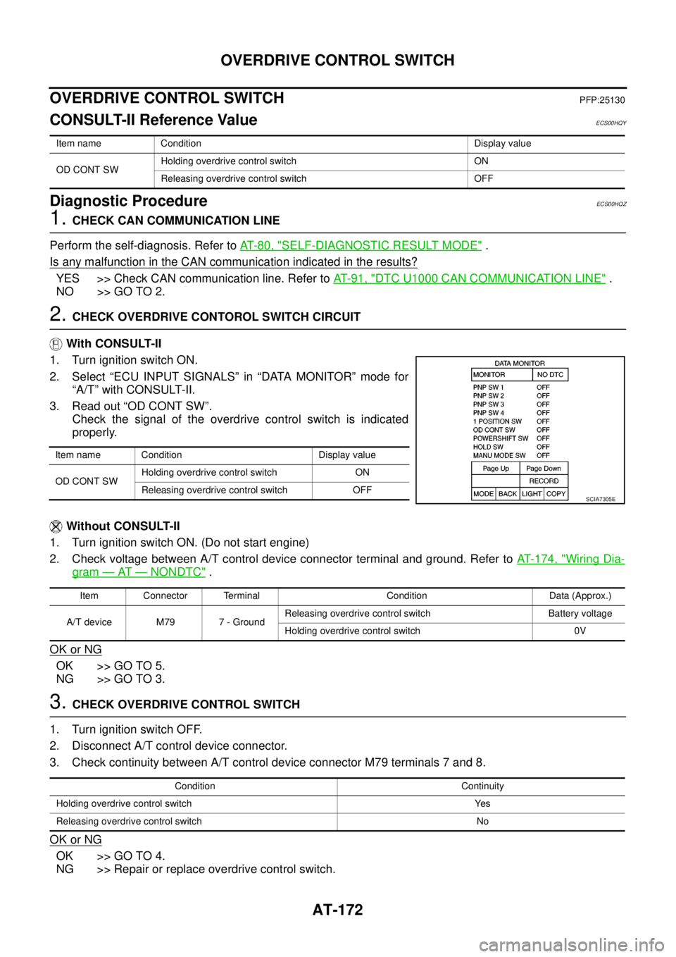
With CONSULT-II
1. Turn ignition switch ON.
2. Select “ECU INPUT SIGNALS” in “DATA MONITOR” mode for
“A/T” with CONSULT-II.
3. Read out “OD CONT SW”.
Check the signal of the overdrive control switch is indicated
properly.
Without CONSULT-II
1. Turn ignition switch ON. (Do not start engine)
2. Check voltage between A/T control device connector terminal and ground. Refer toAT- 1 7 4 , "
Wiring Dia-
gram—AT—NONDTC".
OK or NG
OK >> GO TO 5.
NG >> GO TO 3.
3.CHECK OVERDRIVE CONTROL SWITCH
1. Turn ignition switch OFF.
2. Disconnect A/T control device connector.
3. Check continuity between A/T control device connector M79 terminals 7 and 8.
OK or NG
OK >> GO TO 4.
NG >> Repair or replace overdrive control switch.
Item name Condition Display value
OD CONT SWHolding overdrive control switch ON
Releasing overdrive control switch OFF
Item name Condition Display value
OD CONT SWHolding overdrive control switch ON
Releasing overdrive control switch OFF
SCIA7305E
Item Connector Terminal Condition Data (Approx.)
A/T device M79 7 - GroundReleasing overdrive control switch Battery voltage
Holding overdrive control switch 0V
Condition Continuity
Holding overdrive control switch Yes
Releasing overdrive control switch No
Page 185 of 3171
TROUBLE DIAGNOSIS FOR SYMPTOMS
AT-177
D
E
F
G
H
I
J
K
L
MA
B
AT
Data are reference value and are measured between each terminal and ground.
OD OFF Indicator Lamp Does Not Come OnECS00G2B
SYMPTOM:
OD OFF indicator lamp does not come on for about 2 seconds when turning ignition switch ON.
DIAGNOSTIC PROCEDURE
1.CHECK CAN COMMUNICATION LINE
Perform self-diagnosis. Refer toAT-80, "
SELF-DIAGNOSTIC RESULT MODE",AT-89, "Diagnostic Procedure
Without CONSULT-II".
Is a malfunction in the CAN communication indicated in the results?
YES >> Check CAN communication line. Refer toAT-91, "DTC U1000 CAN COMMUNICATION LINE".
NO >> GO TO 2.
2.CHECK OD OFF INDICATOR LAMP CIRCUIT
Check combination meter. Refer toDI-4, "
COMBINATION METERS".
OK or NG
OK >> GO TO 3
NG >> Repair or replace damaged parts.
3.CHECK TCM POWER SUPPLY AND GROUND CIRCUIT
Check TCM power supply and ground circuit. Refer toAT- 1 6 4 , "
MAIN POWER SUPPLY AND GROUND CIR-
CUIT".
OK or NG
OK >>INSPECTION END
NG >> Repair or replace damaged parts.
Engine Cannot Be Started in “P” or “N” PositionECS00G2C
SYMPTOM:
lEngine cannot be started with selector lever in “P” or “N” position.
lEngine can be started with selector lever in “R”, “D”, “3”, “2” or “1” position.
DIAGNOSTIC PROCEDURE
1.CHECK SELF-DIAGNOSIS RESULTS
Perform self-diagnosis. Refer toAT-80, "
SELF-DIAGNOSTIC RESULT MODE",AT-89, "Diagnostic Procedure
Without CONSULT-II".
Do the self-diagnosis results indicate PNP switch?
YES >> Check malfunctioning system. Refer toAT-99, "DTC P0705 PARK/NEUTRAL POSITION
SWITCH".
NO >> GO TO 2.
TerminalWire
colorItem Condition Data (Approx.)
3 L CAN-H – –
4GRK-line (CONSULT-
II signal)The terminal is connected to the data link connector for CONSULT-II. –
7LGBack-up lamp
relaySelector lever in “R” position. 0V
Selector lever in other positions. Battery voltage
8 P CAN-L – –
9BRStarterrelaySelector lever in “N” or “P” position. Battery voltage
Selector lever in other positions. 0V
Page 188 of 3171
AT-180
TROUBLE DIAGNOSIS FOR SYMPTOMS
Large Shock (“N” to “D” Position)
ECS00G2F
SYMPTOM:
A noticeable shock occurs when selector lever is shifted from the “N” to “D” position.
DIAGNOSTIC PROCEDURE
1.CHECK SELF-DIAGNOSTIC RESULTS
Perform self-diagnosis. Refer toAT-80, "
SELF-DIAGNOSTIC RESULT MODE",AT-89, "Diagnostic Procedure
Without CONSULT-II".
Is any malfunction detected by self-diagnostic results?
YES >> Check malfunctioning system. Refer toAT-80, "SELF-DIAGNOSTIC RESULT MODE",AT- 9 0 ,
"Judgement Self-diagnosis Code".
NO >> GO TO 2.
2.CHECK ENGINE IDLE SPEED
Check engine idle speed. Refer toEC-38, "
Basic Inspection".
OK or NG
OK >> GO TO 3.
NG >> Adjust engine idle speed. Refer toEC-38, "
Basic Inspection".
3.CHECK CONTROL CABLE
Check control cable. Refer toAT- 2 11 , "
Checking of A/T Position".
OK or NG
OK >> GO TO 4.
NG >> Adjust control cable. Refer toAT- 2 11 , "
Adjustment of A/T Position".
4.CHECK A/T FLUID LEVEL
Check A/T fluid level. Refer toAT-12, "
Checking A/T Fluid".
OK or NG
OK >> GO TO 5.
NG >> Refill ATF.
5.CHECK LINE PRESSURE
Check line pressure at idle with selector lever in “D” position. Refer toAT-44, "
LINE PRESSURE TEST".
OK or NG
OK >> GO TO 8.
NG - 1 >> Line pressure high: GO TO 6.
NG - 2 >> Line pressure low: GO TO 7.
6.DETECT MALFUNCTIONING ITEM
1. Check control valve with TCM. Refer toAT- 2 1 8 , "
Control Valve With TCM and A/T Fluid Temperature Sen-
sor 2".
2. Disassemble A/T. Refer toAT- 2 6 3 , "
DISASSEMBLY".
3. Check the following.
–Oil pump assembly. Refer toAT- 2 8 1 , "Oil Pump".
OK or NG
OK >> GO TO 8.
NG >> Repair or replace damaged parts.
Page 190 of 3171
AT-182
TROUBLE DIAGNOSIS FOR SYMPTOMS
Vehicle Does Not Creep Backward in “R” Position
ECS00G2G
SYMPTOM:
The vehicle does not creep in the “R” position. Or an extreme lack of acceleration is observed.
DIAGNOSTIC PROCEDURE
1.CHECK SELF-DIAGNOSTIC RESULTS
Perform self-diagnosis. Refer toAT-80, "
SELF-DIAGNOSTIC RESULT MODE",AT-89, "Diagnostic Procedure
Without CONSULT-II".
Is any malfunction detected by self-diagnostic results?
YES >> Check malfunctioning system. Refer toAT-80, "SELF-DIAGNOSTIC RESULT MODE",AT- 9 0 ,
"Judgement Self-diagnosis Code"
NO >> GO TO 2.
2.CHECK CONTROL CABLE
Check control cable. Refer toAT- 2 11 , "
Checking of A/T Position".
OK or NG
OK >> GO TO 3.
NG >> Adjust control cable. Refer toAT- 2 11 , "
Adjustment of A/T Position".
3.CHECK A/T FLUID LEVEL
Check A/T fluid level. Refer toAT-12, "
Checking A/T Fluid".
OK or NG
OK >> GO TO 4.
NG >> Refill ATF.
4.CHECK STALL TEST
Check stall revolution with selector lever in “1” and “R” positions. Refer toAT-43, "
STALL TEST".
OK or NG
OK >> GO TO 6.
OK in “1” position, NG in “R” position>>GO TO 5.
NG in both “1” and “R” positions>>GO TO 8.
5.DETECT MALFUNCTIONING ITEM
1. Disassemble A/T. Refer toAT- 2 6 3 , "
DISASSEMBLY".
2. Check the following items:
–Reverse brake. Refer toAT- 2 6 3 , "DISASSEMBLY".
OK or NG
OK >> GO TO 9.
NG >> Repair or replace damaged parts.
6.CHECK LINE PRESSURE
Check line pressure with the engine idling. Refer toAT-44, "
LINE PRESSURE TEST".
OK or NG
OK >> GO TO 9.
NG - 1 >> Line pressure high. GO TO 7.
NG - 2 >> Line pressure low. GO TO 8.
Page 194 of 3171
AT-186
TROUBLE DIAGNOSIS FOR SYMPTOMS
12.DETECT MALFUNCTIONING ITEM
Check malfunction items. If any items are damaged, repair or replace damaged parts. Refer toAT-53, "
Symp-
tom Chart"(Symptom No.43).
OK or NG
OK >> GO TO 10.
NG >> Repair or replace damaged parts.
Vehicle Cannot Be Started from D1ECS00G2I
SYMPTOM:
Vehicle cannot be started from D1on“CruiseTest-Part1”and“CruiseTest-Part2”.
DIAGNOSTIC PROCEDURE
1.CONFIRM THE SYMPTOM
Check if vehicle creeps in “R” position.
OK or NG
OK >> GO TO 2.
NG >> Refer toAT- 1 8 2 , "
Vehicle Does Not Creep Backward in“R”Position".
2.CHECK SELF-DIAGNOSTIC RESULTS
Perform self-diagnosis. Refer toAT-80, "
SELF-DIAGNOSTIC RESULT MODE",AT-89, "Diagnostic Procedure
Without CONSULT-II".
Is any malfunction detected by self-diagnostic results?
YES >> Check malfunctioning system. Refer toAT-80, "SELF-DIAGNOSTIC RESULT MODE",AT- 9 0 ,
"Judgement Self-diagnosis Code".
NO >> GO TO 3.
3.CHECK ACCELERATOR PEDAL POSITION SENSOR
Check accelerator pedal position sensor. Refer toAT- 11 6 , "
DTC P1705 THROTTLE POSITION SENSOR".
OK or NG
OK >> GO TO 4.
NG >> Repair or replace accelerator pedal position sensor.
4.CHECK A/T FLUID LEVEL
Check A/T fluid level. Refer toAT-12, "
Checking A/T Fluid".
OK or NG
OK >> GO TO 5.
NG >> Refill ATF.
5.CHECK LINE PRESSURE
Check line pressure at the engine stall point. Refer toAT-44, "
LINE PRESSURE TEST".
OK or NG
OK >> GO TO 8.
NG - 1 >> Line pressure high. GO TO 6.
NG - 2 >> Line pressure low. GO TO 7.
Page 196 of 3171
AT-188
TROUBLE DIAGNOSIS FOR SYMPTOMS
12.DETECT MALFUNCTIONING ITEM
Check malfunction items. If any items are damaged, repair or replace damaged parts. Refer toAT-53, "
Symp-
tom Chart"(Symptom No.23).
OK or NG
OK >> GO TO 10.
NG >> Repair or replace damaged parts.
A/T Does Not Shift: D1®D2ECS00G2J
SYMPTOM:
The vehicle does not shift-up from D1to D2gear at the specified speed.
DIAGNOSTIC PROCEDURE
1.CONFIRM THE SYMPTOM
Check if vehicle creeps forward in “D” position and vehicle can be started from D
1.
OK or NG
OK >> GO TO 2.
NG >> Refer toAT- 1 8 4 , "
Vehicle Does Not Creep Forward in“D”Position",AT- 1 8 6 , "Vehicle Cannot Be
Start ed fro m D1".
2.CHECK SELF-DIAGNOSTIC RESULTS
Perform self-diagnosis. Refer toAT-80, "
SELF-DIAGNOSTIC RESULT MODE",AT-89, "Diagnostic Procedure
Without CONSULT-II".
Is any malfunction detected by self-diagnostic results?
YES >> Check malfunctioning system. Refer toAT-80, "SELF-DIAGNOSTIC RESULT MODE",AT- 9 0 ,
"Judgement Self-diagnosis Code".
NO >> GO TO 3.
3.CHECK A/T FLUID LEVEL
Check A/T fluid level. Refer toAT-12, "
Checking A/T Fluid".
OK or NG
OK >> GO TO 4.
NG >> Refill ATF.
4.CHECK LINE PRESSURE
Check line pressure at the engine stall point. Refer toAT-44, "
LINE PRESSURE TEST".
OK or NG
OK >> GO TO 7.
NG - 1 >> Line pressure high. GO TO 5.
NG - 2 >> Line pressure low. GO TO 6.
5.DETECT MALFUNCTIONING ITEM
1. Check control valve with TCM. Refer toAT- 2 1 8 , "
Control Valve With TCM and A/T Fluid Temperature Sen-
sor 2".
2. Disassemble A/T. Refer toAT- 2 6 3 , "
DISASSEMBLY".
3. Check the following.
–Oil pump assembly. Refer toAT- 2 8 1 , "Oil Pump".
OK or NG
OK >> GO TO 7.
NG >> Repair or replace damaged parts.
Page 198 of 3171
AT-190
TROUBLE DIAGNOSIS FOR SYMPTOMS
A/T Does Not Shift: D
2®D3ECS00G2K
SYMPTOM:
The vehicle does not shift-up from D2to D3gear at the specified speed.
DIAGNOSTIC PROCEDURE
1.CONFIRM THE SYMPTOM
Check if vehicle creeps forward in “D” position and vehicle can be started from D
1.
OK or NG
OK >> GO TO 2.
NG >> Refer toAT- 1 8 4 , "
Vehicle Does Not Creep Forward in“D”Position",AT- 1 8 6 , "Vehicle Cannot Be
Start ed fro m D1".
2.CHECK SELF-DIAGNOSTIC RESULTS
Perform self-diagnosis. Refer toAT-80, "
SELF-DIAGNOSTIC RESULT MODE",AT-89, "Diagnostic Procedure
Without CONSULT-II".
Is any malfunction detected by self-diagnostic results?
YES >> Check malfunctioning system. Refer toAT-80, "SELF-DIAGNOSTIC RESULT MODE",AT- 9 0 ,
"Judgement Self-diagnosis Code".
NO >> GO TO 3.
3.CHECK A/T FLUID LEVEL
Check A/T fluid level. Refer toAT-12, "
Checking A/T Fluid".
OK or NG
OK >> GO TO 4.
NG >> Refill ATF.
4.CHECK LINE PRESSURE
Check line pressure at the engine stall point. Refer toAT-44, "
LINE PRESSURE TEST".
OK or NG
OK >> GO TO 7.
NG - 1 >> Line pressure high. GO TO 5.
NG - 2 >> Line pressure low. GO TO 6.
5.DETECT MALFUNCTIONING ITEM
1. Check control valve with TCM. Refer toAT- 2 1 8 , "
Control Valve With TCM and A/T Fluid Temperature Sen-
sor 2".
2. Disassemble A/T. Refer toAT- 2 6 3 , "
DISASSEMBLY".
3. Check the following.
–Oil pump assembly. Refer toAT- 2 8 1 , "Oil Pump".
OK or NG
OK >> GO TO 7.
NG >> Repair or replace damaged parts.