2005 NISSAN NAVARA engine
[x] Cancel search: enginePage 845 of 3171
![NISSAN NAVARA 2005 Repair Workshop Manual TROUBLE DIAGNOSIS
BRC-23
[ABS]
C
D
E
G
H
I
J
K
L
MA
B
BRC
For Fast and Accurate DiagnosisEFS005TX
PRECAUTIONS FOR DIAGNOSIS
lBefore performing diagnosis, always read precautions. Refer toBRC-17, "CONS NISSAN NAVARA 2005 Repair Workshop Manual TROUBLE DIAGNOSIS
BRC-23
[ABS]
C
D
E
G
H
I
J
K
L
MA
B
BRC
For Fast and Accurate DiagnosisEFS005TX
PRECAUTIONS FOR DIAGNOSIS
lBefore performing diagnosis, always read precautions. Refer toBRC-17, "CONS](/manual-img/5/57362/w960_57362-844.png)
TROUBLE DIAGNOSIS
BRC-23
[ABS]
C
D
E
G
H
I
J
K
L
MA
B
BRC
For Fast and Accurate DiagnosisEFS005TX
PRECAUTIONS FOR DIAGNOSIS
lBefore performing diagnosis, always read precautions. Refer toBRC-17, "CONSULT- II Functions".
lAfter diagnosis is finished, be sure to erase memory. Refer toBRC-18, "ERASE MEMORY".
lWhen checking continuity and voltage between units, be sure to check for disconnection, looseness,
bend, or collapse of connector terminals. If any malfunction is found, repair or replace connector termi-
nals.
lFor intermittent symptoms, possible cause is malfunction in harness, harness connector, or terminals.
Move harness, harness connector, and terminals to check for poor connections.
lIf a circuit tester is used for check, be careful not to forcibly extend any connector terminal.
lABS system electrically controls brake operation and engine output. Following symptoms may be caused
by normal operations:
Basic InspectionEFS005TY
BASIC INSPECTION 1 BRAKE FLUID LEVEL, LEAKS, AND BRAKE PADS
1. Check fluid level in the brake reservoir tank. If fluid level is low, refill brake fluid.
2. Check brake tube and around ABS actuator and electric unit (control unit) for leaks. If leakage or seepage
is found, check the following items.
lIf ABS actuator and electric unit (control unit) connection is loose, tighten brake tube to the specified
torque and re-conduct the leak inspection to make sure there are no leakage.
lIf there is damage to the connection flare nut or ABS actuator and electric unit (control unit) screw,
replace the damaged part and re-conduct the leak inspection to make sure there are no leakage.
lIf there is leakage or seepage at any location other than ABS actuator and electric unit (control unit)
connection, wipe away leakage or seepage with clean cloth. Then inspect again and confirm than there
is on leakage.
lIf there is leakage from ABS actuator and electric unit (control unit), wipe away leakage or seepage with
clean cloth. Then inspect again. If there is leakage or seepage, replace ABS actuator and electric unit
(control unit).
CAUTION:
ABS actuator and electric unit (control unit) body cannot be disassembled.
3. Check brake pad degree of wear. Refer toBR-24, "
PAD WEAR INSPECTION"in “Front Disc Brake” and
BR-32, "
Lining Thickness Inspection"in “Rear Drum Brake”.
BASIC INSPECTION 2 POWER SYSTEM TERMINAL LOOSENESS AND BATTERY INSPECTION
Make sure battery positive cable, negative cable and ground connection are not loose. In addition, check the
battery voltage to make sure it has not dropped and alternator is normal.
Symptom Symptom description Result
Motor operation noiseThis is noise of motor inside ABS actuator and electric unit (control unit). Slight
noise may occur during ABS operation.
Normal
Just after engine starts, motor operating noise may be heard. This is a normal
status of the system operation check.
System operation check noiseWhen engine starts, slight “click” noise may be heard from engine compart-
ment. This is normal and is part of system operation check.Normal
ABS operation
(Longer stopping distance)When driving on roads with a low coefficient of friction, such as snowy roads
or gravel roads, the stopping distance is sometimes longer for vehicles
equipped with ABS. Therefore, when driving on such roads, drive at a suffi-
ciently reduced speed to be safe.Normal
Page 846 of 3171
![NISSAN NAVARA 2005 Repair Workshop Manual BRC-24
[ABS]
TROUBLE DIAGNOSIS
BASIC INSPECTION 3 ABS WARNING LAMP AND BRAKE WARNING LAMP INSPECTION
ON and OFF Timing for ABS Warning Lamp, Brake Warning Lamp
´:ON –:OFF
Note 1:Brake warning lamp NISSAN NAVARA 2005 Repair Workshop Manual BRC-24
[ABS]
TROUBLE DIAGNOSIS
BASIC INSPECTION 3 ABS WARNING LAMP AND BRAKE WARNING LAMP INSPECTION
ON and OFF Timing for ABS Warning Lamp, Brake Warning Lamp
´:ON –:OFF
Note 1:Brake warning lamp](/manual-img/5/57362/w960_57362-845.png)
BRC-24
[ABS]
TROUBLE DIAGNOSIS
BASIC INSPECTION 3 ABS WARNING LAMP AND BRAKE WARNING LAMP INSPECTION
ON and OFF Timing for ABS Warning Lamp, Brake Warning Lamp
´:ON –:OFF
Note 1:Brake warning lamp will turn on in case of operating parking brake (switch turned on) or of a actuating brake fluid level switch
(brake fluid is insufficient).
Note 2:After starting engine, turn OFF.
Check the following items when unsuitable for an above condition.
lABS warning lamp: Refer toBRC-28, "Inspection 4 CAN Communication Circuit".
lBrake waning lamp: Refer toBRC-28, "Inspection 4 CAN Communication Circuit",BRC-30, "Inspection 6
Brake Fluid Level Switch Circuit",BRC-32, "Inspection 7 Parking Brake Switch Circuit".
If malfunction is not found, refer toBRC-33, "
Inspection 8 Warning lamp system".
Inspection 1 Wheel Sensor SystemEFS005TZ
Check each part according to CONSULT-II self-diagnostic results, and then identify the parts to be replaced.
CAUTION:
Check each part between wheel sensor terminals.
INSPECTION PROCEDURE
1.CHECK SELF-DIAGNOSTIC RESULTS
Check self-diagnostic results.
Is above displayed in self-diagnosis display items?
YES >> GO TO 2.
NO >> INSPECTION END
2.CHECK TYRE
Check air pressure, wear and size.
Are air pressure, wear and size within standard values?
YES >> GO TO 3.
NO >> Adjust air pressure, or replace tyre.
Condition ABS warning lampBrake warning lamp
[Note 1]Remarks
Ignition SW OFF – — —
Approx. 2 seconds after ignition
switch is turned ON´´[Note 2] —
Approx. 2 seconds later after ignition
switch ON–´[Note 2]Go out 2 seconds after ignition
switch is turned ON.
ABS error´—There is an ABS actuator and
electric unit (control unit) error.
(Power, ground or system mal-
function)
EBD error´´—
Self-diagnostic results
FR RH SENSOR-1,-2
FR LH SENSOR- 1,-2
RR RH SENSOR-1,-2
RR LH SENSOR-1,- 2
ABS SENSOR [MALFUNCTION SIGNAL]
Page 857 of 3171
![NISSAN NAVARA 2005 Repair Workshop Manual TROUBLE DIAGNOSIS
BRC-35
[ABS]
C
D
E
G
H
I
J
K
L
MA
B
BRC
Symptom 4: ABS Function Does Not OperateEFS005UB
CAUTION:
ABS does not operate when speed is 10 km/h (6 MPH) or lower.
1.CHECK ABS WARNING LAM NISSAN NAVARA 2005 Repair Workshop Manual TROUBLE DIAGNOSIS
BRC-35
[ABS]
C
D
E
G
H
I
J
K
L
MA
B
BRC
Symptom 4: ABS Function Does Not OperateEFS005UB
CAUTION:
ABS does not operate when speed is 10 km/h (6 MPH) or lower.
1.CHECK ABS WARNING LAM](/manual-img/5/57362/w960_57362-856.png)
TROUBLE DIAGNOSIS
BRC-35
[ABS]
C
D
E
G
H
I
J
K
L
MA
B
BRC
Symptom 4: ABS Function Does Not OperateEFS005UB
CAUTION:
ABS does not operate when speed is 10 km/h (6 MPH) or lower.
1.CHECK ABS WARNING LAMP DISPLAY
Make sure that the ABS warning lamp is turned off after the ignition switch is turned ON or when driving.
OK or NG
OK >> GO TO procedure 3 “CHECK WHEEL SENSOR AND SENSOR ROTOR” of symptom1. Refer to
BRC-33, "
Symptom 1: Excessive ABS Function Operation Frequency".
NG >> Perform self-diagnosis. Refer toBRC-18, "
Self-Diagnosis".
Symptom 5: Pedal Vibration or ABS Operation Sound OccursEFS005UC
CAUTION:
Under the following conditions, ABS is activated and vibration is felt when brake pedal is lightly
depressed (just place a foot on it). However, this is normal.
lWhen shifting gears
lWhen driving on slippery road
lDuring cornering at high speed
lWhen passing over bumps or grooves [at approximately 50 mm (1.97 in) or more]
lWhen pulling away just after starting engine [at approximately 10 km/h (6 MPH) or more]
1.SYMPTOM CHECK 1
Check if there is pedal vibration or operation noise when the engine is started.
Do symptoms occur?
YES >> GO TO 2.
NO >> Perform self-diagnosis. Refer toBRC-18, "
Self-Diagnosis".
2.SYMPTOM CHECK 2
Check symptoms when electrical component (headlamps, etc.) switches are operated.
Do symptoms occur?
YES >> Check if there is a radio, antenna, antenna lead wire, or wiring close to the control unit. If there is,
move it farther away.
NO >> GO TO procedure 3²CHECK WHEEL SENSOR AND SENSOR ROTOR²of symptom 1. Refer to
BRC-33, "
Symptom 1: Excessive ABS Function Operation Frequency".
Symptom 6: ABS Warning Lamp Indication Is Not NormalEFS005UD
NOTE:
Lighting condition of ABS warning lamp refer toBRC-24, "
BASIC INSPECTION 3 ABS WARNING LAMP AND
BRAKE WARNING LAMP INSPECTION".
1.CHECK COMBINATION METER INDICATION
Check the combination meter indication and operation. Refer toDI-13, "
Self-Diagnosis Mode of Combination
Meter".
OK or NG
OK >> GO TO 2.
NG >> Combination meter is malfunctioning. Check combination meter. Refer toDI-4, "
COMBINATION
METERS".
Page 869 of 3171

NOISE, VIBRATION AND HARSHNESS (NVH) TROUBLESHOOTING
CL-5
D
E
F
G
H
I
J
K
L
MA
B
CL
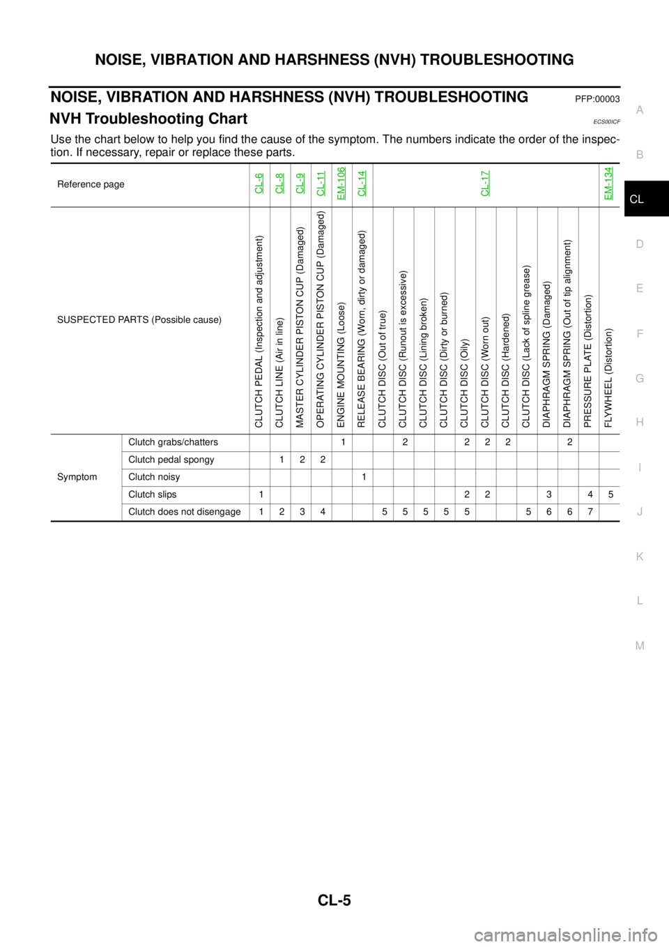
NOISE, VIBRATION AND HARSHNESS (NVH) TROUBLESHOOTINGPFP:00003
NVH Troubleshooting ChartECS00ICF
Use the chart below to help you find the cause of the symptom. The numbers indicate the order of the inspec-
tion. If necessary, repair or replace these parts.
Reference pageCL-6CL-8CL-9CL-11EM-106CL-14CL-17EM-134
SUSPECTED PARTS (Possible cause)
CLUTCH PEDAL (Inspection and adjustment)
CLUTCH LINE (Air in line)
MASTER CYLINDER PISTON CUP (Damaged)
OPERATING CYLINDER PISTON CUP (Damaged)
ENGINE MOUNTING (Loose)
RELEASE BEARING (Worn, dirty or damaged)
CLUTCH DISC (Out of true)
CLUTCH DISC (Runout is excessive)
CLUTCH DISC (Lining broken)
CLUTCH DISC (Dirty or burned)
CLUTCH DISC (Oily)
CLUTCH DISC (Worn out)
CLUTCH DISC (Hardened)
CLUTCH DISC (Lack of spline grease)
DIAPHRAGM SPRING (Damaged)
DIAPHRAGM SPRING (Out of tip alignment)
PRESSURE PLATE (Distortion)
FLYWHEEL (Distortion)
SymptomClutch grabs/chatters 1 2 2 2 2 2
Clutch pedal spongy 1 2 2
Clutch noisy 1
Clutch slips 1 2 2 3 4 5
Clutch does not disengage 1 2 3 4 5 5 5 5 5 5 6 6 7
Page 885 of 3171

CO-1
ENGINE COOLING SYSTEM
B ENGINE
CONTENTS
C
D
E
F
G
H
I
J
K
L
M
SECTIONCO
A
CO
ENGINE COOLING SYSTEM
PRECAUTIONS .......................................................... 2
Precautions For Liquid Gasket ................................. 2
LIQUID GASKET APPLICATION PROCEDURE..... 2
PREPARATION ........................................................... 3
Special Service Tools ............................................... 3
Commercial Service Tools ........................................ 3
OVERHEATING CAUSE ANALYSIS .......................... 4
Troubleshooting Chart .............................................. 4
COOLING SYSTEM .................................................... 6
Cooling Circuit .......................................................... 6
ENGINE COOLANT .................................................... 7
Inspection ................................................................. 7
LEVEL CHECK ..................................................... 7
CHECKING RADIATOR SYSTEM FOR LEAKS..... 7
Changing Engine Coolant ........................................ 7
DRAINING ENGINE COOLANT ........................... 8
REFILLING ENGINE COOLANT .......................... 8
FLUSHING COOLING SYSTEM ........................... 9
RADIATOR .................................................................11
Components ............................................................ 11
Removal and Installation ......................................... 11
REMOVAL ............................................................ 11
INSPECTION AFTER REMOVAL ....................... 13
INSTALLATION ................................................... 14
INSPECTION AFTER INSTALLATION ............... 14
RADIATOR (ALUMINUM TYPE) .............................. 15
Components ........................................................... 15
Disassembly and Assembly ................................... 15
PREPARATION ................................................... 15
DISASSEMBLY ................................................... 15
ASSEMBLY ......................................................... 16
INSPECTION ...................................................... 18COOLING FAN .......................................................... 19
Components (Crankshaft Driven Type) .................. 19
Removal and Installation ........................................ 19
REMOVAL ........................................................... 19
INSPECTION AFTER REMOVAL ....................... 19
INSTALLATION ................................................... 19
Removal and Installation (Motor Driven Type) (Mod-
els with A/C) ........................................................... 19
REMOVAL ........................................................... 19
INSTALLATION ................................................... 20
WATER PUMP .......................................................... 21
Components ........................................................... 21
Removal and Installation ........................................ 21
REMOVAL ........................................................... 21
INSPECTION AFTER REMOVAL ....................... 22
INSTALLATION ................................................... 22
INSPECTION AFTER INSTALLATION ................ 22
THERMOSTAT AND WATER PIPING ...................... 23
Components ........................................................... 23
Removal and Installation ........................................ 24
REMOVAL ........................................................... 24
INSPECTION AFTER REMOVAL ....................... 24
INSTALLATION ................................................... 24
INSPECTION AFTER INSTALLATION ................ 25
SERVICE DATA AND SPECIFICATIONS (SDS) ...... 26
Standard and Limit .................................................. 26
ENGINE COOLANT CAPACITY .......................... 26
THERMOSTAT .................................................... 26
RESERVOIR TANK ............................................. 26
Page 886 of 3171

CO-2
PRECAUTIONS
PRECAUTIONS
PFP:00001
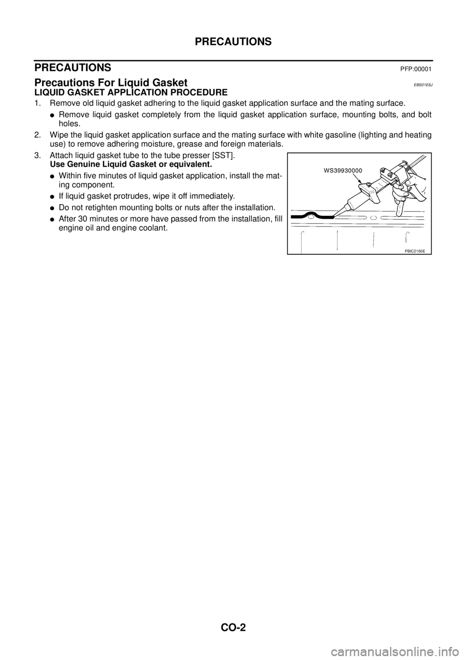
Precautions For Liquid GasketEBS01E6J
LIQUID GASKET APPLICATION PROCEDURE
1. Remove old liquid gasket adhering to the liquid gasket application surface and the mating surface.
lRemove liquid gasket completely from the liquid gasket application surface, mounting bolts, and bolt
holes.
2. Wipe the liquid gasket application surface and the mating surface with white gasoline (lighting and heating
use) to remove adhering moisture, grease and foreign materials.
3. Attach liquid gasket tube to the tube presser [SST].
Use Genuine Liquid Gasket or equivalent.
lWithin five minutes of liquid gasket application, install the mat-
ing component.
lIf liquid gasket protrudes, wipe it off immediately.
lDo not retighten mounting bolts or nuts after the installation.
lAfter 30 minutes or more have passed from the installation, fill
engine oil and engine coolant.
PBIC2160E
Page 888 of 3171

CO-4
OVERHEATING CAUSE ANALYSIS
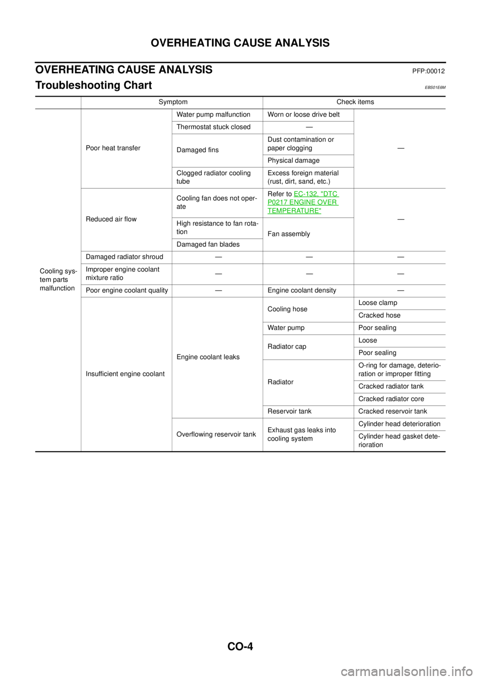
OVERHEATING CAUSE ANALYSIS
PFP:00012
Troubleshooting ChartEBS01E6M
Symptom Check items
Cooling sys-
tem parts
malfunctionPoor heat transferWater pump malfunction Worn or loose drive belt
— Thermostat stuck closed —
Damaged finsDust contamination or
paper clogging
Physical damage
Clogged radiator cooling
tubeExcess foreign material
(rust, dirt, sand, etc.)
Reduced air flowCooling fan does not oper-
ateRefer toEC-132, "
DTC
P0217 ENGINE OVER
TEMPERATURE"
—
Highresistancetofanrota-
tion
Fan assembly
Damaged fan blades
Damaged radiator shroud — — —
Improper engine coolant
mixture ratio—— —
Poor engine coolant quality — Engine coolant density —
Insufficient engine coolantEngine coolant leaksCooling hoseLoose clamp
Cracked hose
Water pump Poor sealing
Radiator capLoose
Poor sealing
RadiatorO-ring for damage, deterio-
ration or improper fitting
Cracked radiator tank
Cracked radiator core
Reservoir tank Cracked reservoir tank
Overflowing reservoir tankExhaust gas leaks into
cooling systemCylinder head deterioration
Cylinder head gasket dete-
rioration
Page 889 of 3171

OVERHEATING CAUSE ANALYSIS
CO-5
C
D
E
F
G
H
I
J
K
L
MA
CO
Except cool-
ing system
parts mal-
function— Overload on engineAbusive drivingHigh engine rpm under no
load
Driving in low gear for
extended time
Driving at extremely high
speed
Powertrain system mal-
function
— Installed improper size
wheels and tires
Dragging brakes
Improper ignition timing
Blocked or restricted air
flowBlocked bumper —
— Blocked radiator grilleInstalled car brassiere
Mud contamination or
paper clogging
Blocked radiator —
Blocked condenser
Blocked air flow
Installed large fog lamp Symptom Check items