2005 NISSAN NAVARA length
[x] Cancel search: lengthPage 806 of 3171
BR-20
BRAKE BOOSTER
Removal and Installation
EFS005SU
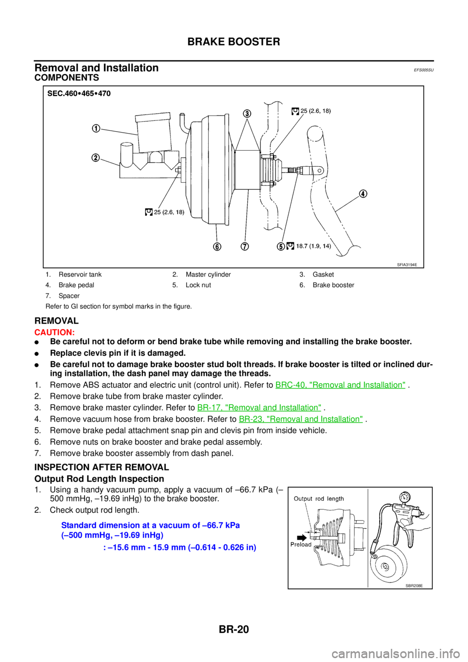
COMPONENTS
REMOVAL
CAUTION:
lBe careful not to deform or bend brake tube while removing and installing the brake booster.
lReplace clevis pin if it is damaged.
lBe careful not to damage brake booster stud bolt threads. If brake booster is tilted or inclined dur-
ing installation, the dash panel may damage the threads.
1. Remove ABS actuator and electric unit (control unit). Refer toBRC-40, "
Removal and Installation".
2. Remove brake tube from brake master cylinder.
3. Remove brake master cylinder. Refer toBR-17, "
Removal and Installation".
4. Remove vacuum hose from brake booster. Refer toBR-23, "
Removal and Installation".
5. Remove brake pedal attachment snap pin and clevis pin from inside vehicle.
6. Remove nuts on brake booster and brake pedal assembly.
7. Remove brake booster assembly from dash panel.
INSPECTION AFTER REMOVAL
Output Rod Length Inspection
1. Using a handy vacuum pump, apply a vacuum of –66.7 kPa (–
500 mmHg, –19.69 inHg) to the brake booster.
2. Check output rod length.
1. Reservoir tank 2. Master cylinder 3. Gasket
4. Brake pedal 5. Lock nut 6. Brake booster
7. Spacer
Refer to GI section for symbol marks in the figure.
SFIA3194E
Standard dimension at a vacuum of –66.7 kPa
(–500 mmHg, –19.69 inHg)
: –15.6 mm - 15.9 mm (–0.614 - 0.626 in)
SBR208E
Page 807 of 3171
BRAKE BOOSTER
BR-21
C
D
E
G
H
I
J
K
L
MA
B
BR
INSTALLATION
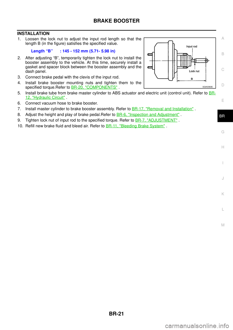
1. Loosen the lock nut to adjust the input rod length so that the
length B (in the figure) satisfies the specified value.
2. After adjusting “B”, temporarily tighten the lock nut to install the
booster assembly to the vehicle. At this time, securely install a
gasket and spacer block between the booster assembly and the
dash panel.
3. Connect brake pedal with the clevis of the input rod.
4. Install brake booster mounting nuts and tighten them to the
specified torque.Refer toBR-20, "
COMPONENTS".
5. Install brake tube from brake master cylinder to ABS actuator and electric unit (control unit). Refer toBR-
12, "Hydraulic Circuit".
6. Connect vacuum hose to brake booster.
7. Install master cylinder to brake booster assembly. Refer toBR-17, "
Removal and Installation".
8. Adjust the height and play of brake pedal.Refer toBR-6, "
Inspection and Adjustment".
9. Tighten lock nut of input rod to the specified torque. Refer toBR-7, "
ADJUSTMENT".
10. Refill new brake fluid and bleed air. Refer toBR-11, "
Bleeding Brake System". Length“B” :145-152mm(5.71-5.98in)
SGIA0060E
Page 821 of 3171

SERVICE DATA AND SPECIFICATIONS (SDS)
BR-35
C
D
E
G
H
I
J
K
L
MA
B
BR
SERVICE DATA AND SPECIFICATIONS (SDS)PFP:00030
General SpecificationsEFS005T8
Unit: mm (in)
Brake PedalEFS005T9
Unit: mm (in)
Brake BoosterEFS005TA
Va c u u m t y p e
Unit: mm (in)
Check ValveEFS005TB
Front Disc BrakeEFS005TC
Unit: mm (in) Front brake Brake model CLZ33VB
Cylinder bore diameter 46.4 (1.83)´2
Pad length´width´thickness 140´47.8´11 ( 5 . 5 1´1.88´0.43)
Rotor outer diameter´thickness 296´28 (11.65´1.10)
Rear brake Brake model LT30
Cylinder bore diameter 38.1 (1.50)
Lining Length´width´thickness 295´55´5.5 (11.61´2.17´0.22)
Drum inner diameter 295 (11.61)
Master cylinder Cylinder bore diameter 25.4 (1.0)
Control valve Valve model Electric brake force distribution
Brake booster Booster model C215T
Diaphragm diameterPrimary 228.5 (9.0)
Secondary 203 (8.0)
Recommended brake fluid DOT 3 or DOT 4
Brake pedal height (From dash lower panel top surface)LHD modelA/T 164.1-174.1 (6.46-6.85)
M/T 171.2-181.2 (6.74-7.13)
RHD modelA/T 174.7-184.7 (6.88-7.27)
M/T 182.1-192.1 (7.17-7.56)
Brake pedal depressed height [Under a force of 490 N (50 kg, 110 lb)
with the engine running]LHD model 120 (4.72) or more
RHD model 110 (4.33) or more
Clearance between bracket and the threaded end of the stop lamp switch 0.74 - 1.96 (0.0291 - 0.0772)
Pedal play3-11(0.12-0.43)
Input rod installation standard dimension 145 - 152 (5.71 - 5.98)
Vacuum leakage
[at vacuum of –66.7 kPa (–500 mmHg, –19.69 inHg)]within 1.3 kPa (10 mmHg, 0.39 inHg) of vacuum for 15 seconds
Brake modelCLZ33VB
Brake padStandard thickness 11.0 (0.43)
Repair limit thickness 2.0 (0.08)
Disc rotorStandard thickness 28.0 (1.102)
Repair limit 26.0 (1.024)
Thickness variation (measured at 8 positions) 0.005 (0.0002)
Runout limit (with it attached to the vehicle) 0.05 (0.002)
Page 861 of 3171
![NISSAN NAVARA 2005 Repair Workshop Manual SENSOR ROTOR
BRC-39
[ABS]
C
D
E
G
H
I
J
K
L
MA
B
BRC
SENSOR ROTORPFP:47970
Removal and InstallationEFS005UF
FRONT
The sensor rotors are built into the wheel hubs and are not removable. If damaged, rep NISSAN NAVARA 2005 Repair Workshop Manual SENSOR ROTOR
BRC-39
[ABS]
C
D
E
G
H
I
J
K
L
MA
B
BRC
SENSOR ROTORPFP:47970
Removal and InstallationEFS005UF
FRONT
The sensor rotors are built into the wheel hubs and are not removable. If damaged, rep](/manual-img/5/57362/w960_57362-860.png)
SENSOR ROTOR
BRC-39
[ABS]
C
D
E
G
H
I
J
K
L
MA
B
BRC
SENSOR ROTORPFP:47970
Removal and InstallationEFS005UF
FRONT
The sensor rotors are built into the wheel hubs and are not removable. If damaged, replace wheel hub and
bearing assembly. Refer toFAX-5, "
Removal and Installation".
REAR
Removal
1. Remove axle shaft assembly. Refer toRAX-7, "Removal and Installation".
NOTE:
It is necessary to assemble the rear axle to replace the sensor rotor.
2. Pull the sensor rotor of off the axle shaft using Tool and a press.
Installation
1. Install new sensor rotor on axle shaft using a suitable length
steel tube and a press. Make sure sensor rotor is fully seated.
CAUTION:
Do not reuse the old sensor rotor.
2. Install axle shaft assembly. Refer toRAX-7, "
Removal and
Installation".
CAUTION:
Do not reuse the axle oil seal. The axle oil seal must be
replaced every time the axle shaft assembly is removed
from the axle shaft housing.
WFIA0341E
Page 873 of 3171
CLUTCH MASTER CYLINDER
CL-9
D
E
F
G
H
I
J
K
L
MA
B
CL
CLUTCH MASTER CYLINDERPFP:30610
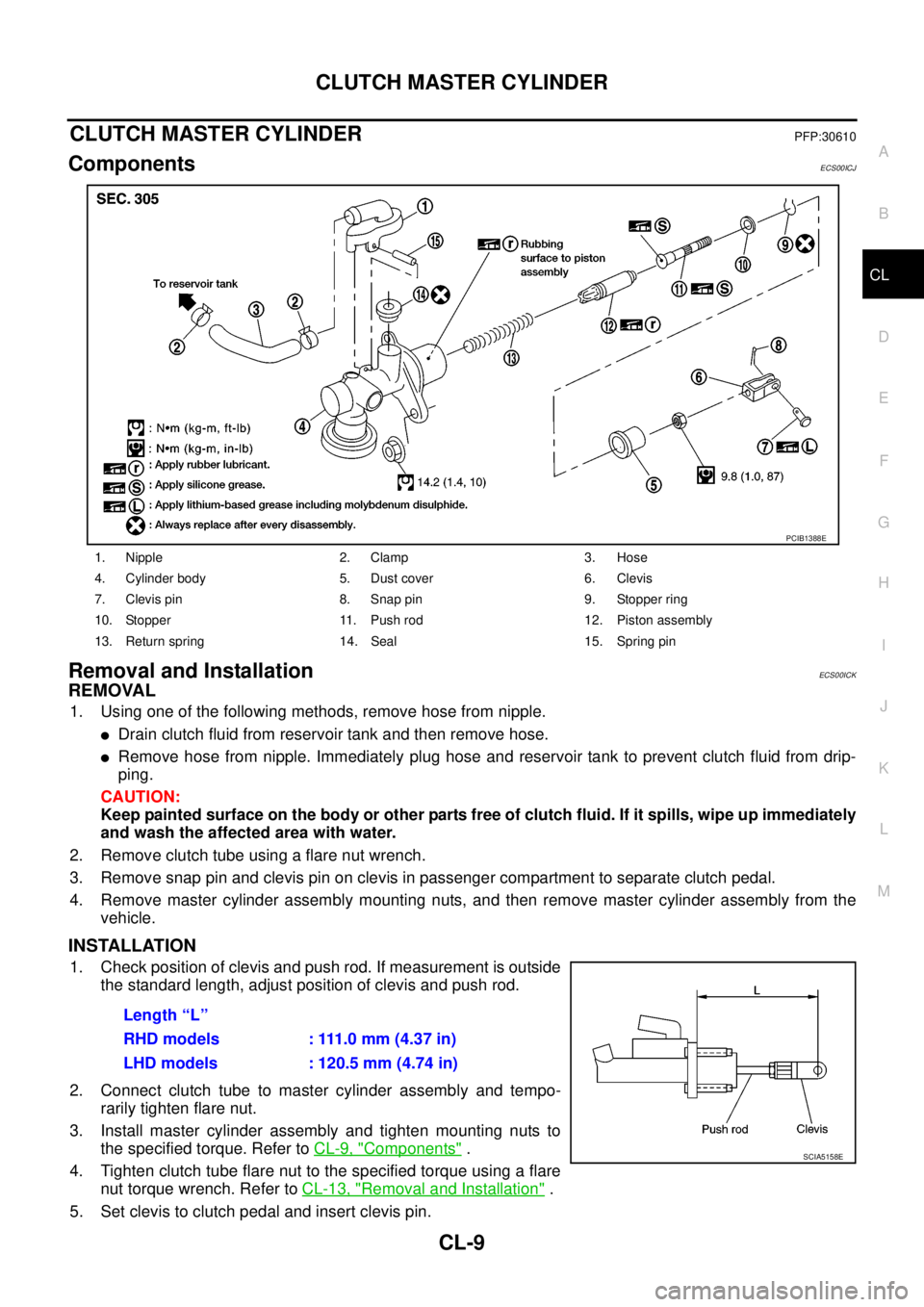
ComponentsECS00ICJ
Removal and InstallationECS00ICK
REMOVAL
1. Using one of the following methods, remove hose from nipple.
lDrain clutch fluid from reservoir tank and then remove hose.
lRemove hose from nipple. Immediately plug hose and reservoir tank to prevent clutch fluid from drip-
ping.
CAUTION:
Keep painted surface on the body or other parts free of clutch fluid. If it spills, wipe up immediately
and wash the affected area with water.
2. Remove clutch tube using a flare nut wrench.
3. Remove snap pin and clevis pin on clevis in passenger compartment to separate clutch pedal.
4. Remove master cylinder assembly mounting nuts, and then remove master cylinder assembly from the
vehicle.
INSTALLATION
1. Check position of clevis and push rod. If measurement is outside
the standard length, adjust position of clevis and push rod.
2. Connect clutch tube to master cylinder assembly and tempo-
rarily tighten flare nut.
3. Install master cylinder assembly and tighten mounting nuts to
the specified torque. Refer toCL-9, "
Components".
4. Tightenclutchtubeflarenuttothespecifiedtorqueusingaflare
nut torque wrench. Refer toCL-13, "
Removal and Installation".
5. Set clevis to clutch pedal and insert clevis pin.
1. Nipple 2. Clamp 3. Hose
4. Cylinder body 5. Dust cover 6. Clevis
7. Clevis pin 8. Snap pin 9. Stopper ring
10. Stopper 11. Push rod 12. Piston assembly
13. Return spring 14. Seal 15. Spring pin
PCIB1388E
Length “L”
RHD models : 111.0 mm (4.37 in)
LHD models : 120.5 mm (4.74 in)
SCIA5158E
Page 874 of 3171
CL-10
CLUTCH MASTER CYLINDER
6. Attach snap pin to clevis pin.
7. Install hose to nipple.
8. After completing this procedure, inspect and adjust for clutch pedal and then bleed the air from the clutch
hydraulic system. Refer toCL-6, "
On-Vehicle Inspection and Adjustment"andCL-8, "Air Bleeding Proce-
dure".
Disassembly and AssemblyECS00ICL
DISASSEMBLY
1. Remove spring pin using a pin punch.
2. Remove nipple and seal from cylinder body.
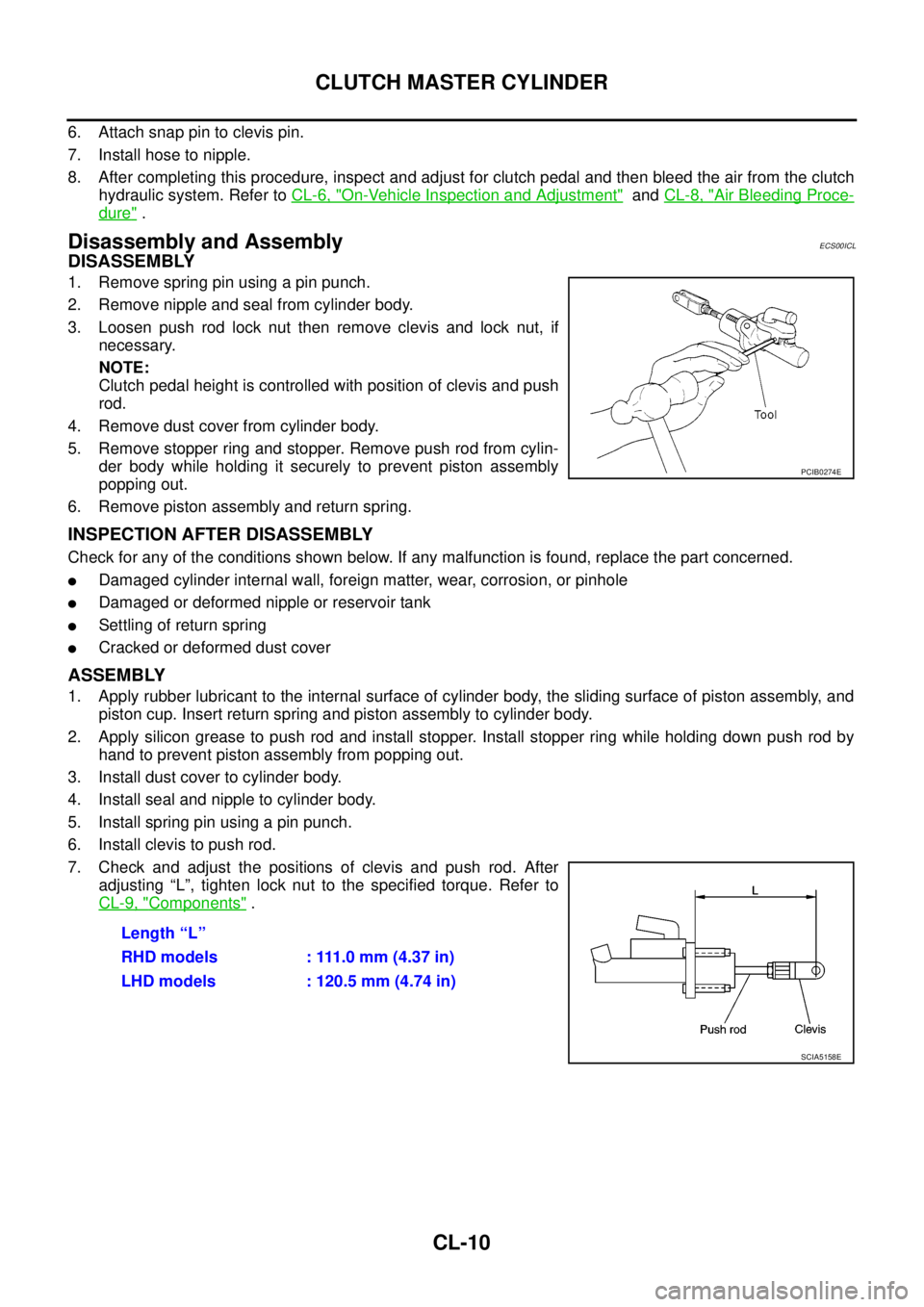
3. Loosen push rod lock nut then remove clevis and lock nut, if
necessary.
NOTE:
Clutch pedal height is controlled with position of clevis and push
rod.
4. Remove dust cover from cylinder body.
5. Remove stopper ring and stopper. Remove push rod from cylin-
der body while holding it securely to prevent piston assembly
popping out.
6. Remove piston assembly and return spring.
INSPECTION AFTER DISASSEMBLY
Check for any of the conditions shown below. If any malfunction is found, replace the part concerned.
lDamaged cylinder internal wall, foreign matter, wear, corrosion, or pinhole
lDamaged or deformed nipple or reservoir tank
lSettling of return spring
lCracked or deformed dust cover
ASSEMBLY
1. Apply rubber lubricant to the internal surface of cylinder body, the sliding surface of piston assembly, and
piston cup. Insert return spring and piston assembly to cylinder body.
2. Apply silicon grease to push rod and install stopper. Install stopper ring while holding down push rod by
hand to prevent piston assembly from popping out.
3. Install dust cover to cylinder body.
4. Install seal and nipple to cylinder body.
5. Install spring pin using a pin punch.
6. Install clevis to push rod.
7. Check and adjust the positions of clevis and push rod. After
adjusting “L”, tighten lock nut to the specified torque. Refer to
CL-9, "
Components".
PCIB0274E
Length “L”
RHD models : 111.0 mm (4.37 in)
LHD models : 120.5 mm (4.74 in)
SCIA5158E
Page 1010 of 3171
EC-30
ON BOARD DIAGNOSTIC (OBD) SYSTEM
How to Erase Diagnostic Test Mode II (Self-diagnostic Results)
1. Set ECM in Diagnostic Test Mode II (Self-diagnostic results). Refer toEC-29, "How to Set Diagnostic Test
Mode II (Self-diagnostic Results)".
2. Fully depress the accelerator pedal and keep it for more than 10 seconds.
The emission-related diagnostic information has been erased from the backup memory in the ECM.
3. Fully release the accelerator pedal, and confirm the DTC 0000 is displayed.
DIAGNOSTIC TEST MODE I — BULB CHECK
In this mode, the MI on the combination meter should stay ON. If it remains OFF, check the bulb. Refer toEC-
354, "MI&DATA LINK CONNECTORS".
DIAGNOSTIC TEST MODE I — MALFUNCTION WARNING
These DTC numbers are clarified in Diagnostic Test Mode II (SELF-DIAGNOSTIC RESULTS)
DIAGNOSTIC TEST MODE II — SELF-DIAGNOSTIC RESULTS
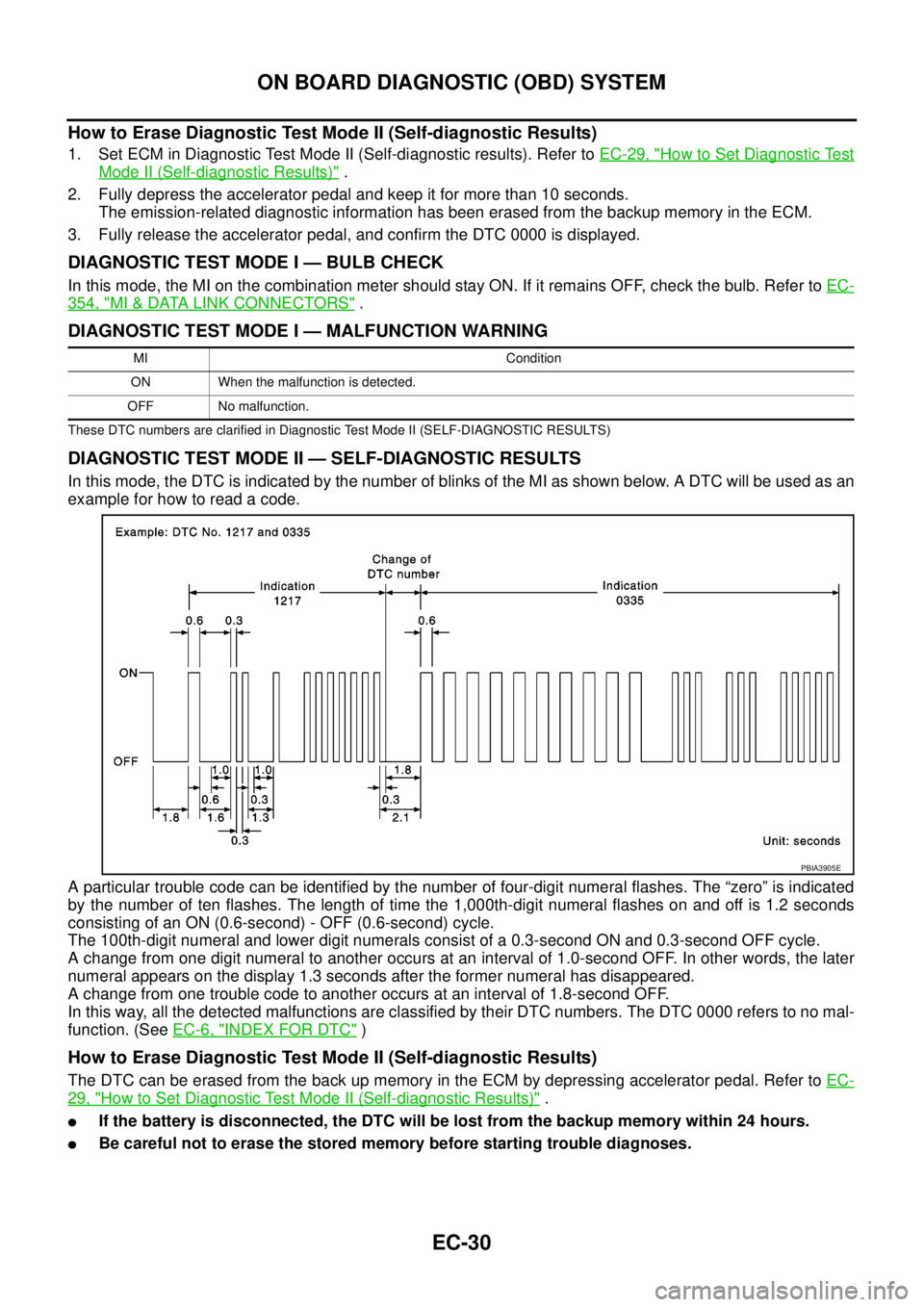
In this mode, the DTC is indicated by the number of blinks of the MI as shown below. A DTC will be used as an
example for how to read a code.
A particular trouble code can be identified by the number of four-digit numeral flashes. The “zero” is indicated
by the number of ten flashes. The length of time the 1,000th-digit numeral flashes on and off is 1.2 seconds
consisting of an ON (0.6-second) - OFF (0.6-second) cycle.
The 100th-digit numeral and lower digit numerals consist of a 0.3-second ON and 0.3-second OFF cycle.
A change from one digit numeral to another occurs at an interval of 1.0-second OFF. In other words, the later
numeral appears on the display 1.3 seconds after the former numeral has disappeared.
A change from one trouble code to another occurs at an interval of 1.8-second OFF.
In this way, all the detected malfunctions are classified by their DTC numbers. The DTC 0000 refers to no mal-
function. (SeeEC-6, "
INDEX FOR DTC")
How to Erase Diagnostic Test Mode II (Self-diagnostic Results)
The DTC can be erased from the back up memory in the ECM by depressing accelerator pedal. Refer toEC-
29, "How to Set Diagnostic Test Mode II (Self-diagnostic Results)".
lIf the battery is disconnected, the DTC will be lost from the backup memory within 24 hours.
lBe careful not to erase the stored memory before starting trouble diagnoses.
MI Condition
ON When the malfunction is detected.
OFF No malfunction.
PBIA3905E
Page 1105 of 3171
DTC P0201 - P0204 FUEL INJECTOR
EC-125
C
D
E
F
G
H
I
J
K
L
MA
EC
DTC P0201 - P0204 FUEL INJECTORPFP:16600
Component DescriptionEBS01KFB
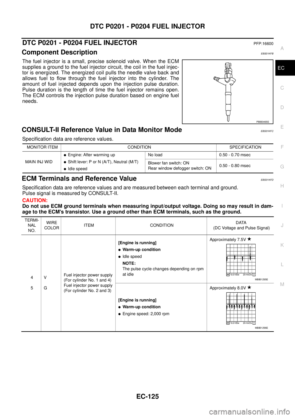
The fuel injector is a small, precise solenoid valve. When the ECM
supplies a ground to the fuel injector circuit, the coil in the fuel injec-
tor is energized. The energized coil pulls the needle valve back and
allows fuel to flow through the fuel injector into the cylinder. The
amount of fuel injected depends upon the injection pulse duration.
Pulse duration is the length of time the fuel injector remains open.
The ECM controls the injection pulse duration based on engine fuel
needs.
CONSULT-II Reference Value in Data Monitor ModeEBS01KFC
Specification data are reference values.
ECM Terminals and Reference ValueEBS01KFD
Specification data are reference values and are measured between each terminal and ground.
Pulse signal is measured by CONSULT-II.
CAUTION:
Do not use ECM ground terminals when measuring input/output voltage. Doing so may result in dam-
age to the ECM's transistor. Use a ground other than ECM terminals, such as the ground.
PBIB0465E
MONITOR ITEM CONDITION SPECIFICATION
MAIN INJ WID
lEngine: After warming up
lShift lever: P or N (A/T), Neutral (M/T)
lIdle speedNo load 0.50 - 0.70 msec
Blower fan switch: ON
Rear window defogger switch: ON0.50 - 0.80 msec
TERMI-
NAL
NO.WIRE
COLORITEM CONDITIONDATA
(DC Voltage and Pulse Signal)
4
5V
GFuel injector power supply
(For cylinder No. 1 and 4)
Fuel injector power supply
(For cylinder No. 2 and 3)[Engine is running]
lWarm-up condition
lIdle speed
NOTE:
The pulse cycle changes depending on rpm
at idleApproximately 7.5V
[Engine is running]
lWarm-up condition
lEngine speed: 2,000 rpmApproximately 8.0V
MBIB1295E
MBIB1296E