2005 NISSAN NAVARA length
[x] Cancel search: lengthPage 1520 of 3171
EM-138
SERVICE DATA AND SPECIFICATIONS (SDS)
Valve Spring
Valve Lifter
Unit: mm (in)
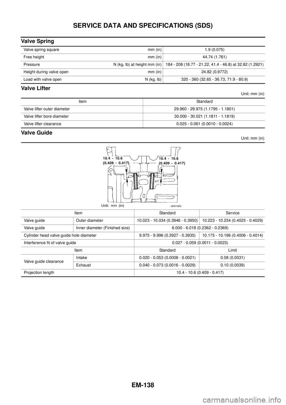
Valve Guide
Unit: mm (in) Valve spring square mm (in) 1.9 (0.075)
Free height mm (in) 44.74 (1.761)
Pressure N (kg, lb) at height mm (in) 184 - 208 (18.77 - 21.22, 41.4 - 46.8) at 32.82 (1.2921)
Height during valve open mm (in) 24.82 (0.9772)
Load with valve open N (kg, lb) 320 - 360 (32.65 - 36.73, 71.9 - 80.9)
Item Standard
Valve lifter outer diameter 29.960 - 29.975 (1.1795 - 1.1801)
Valve lifter bore diameter 30.000 - 30.021 (1.1811 - 1.1819)
Valve lifter clearance 0.025 - 0.061 (0.0010 - 0.0024)
Item Standard Service
Valve guide Outer diameter 10.023 - 10.034 (0.3946 - 0.3950) 10.223 - 10.234 (0.4025 - 0.4029)
Valve guide Inner diameter (Finished size) 6.000 - 6.018 (0.2362 - 0.2369)
Cylinder head valve guide hole diameter 9.975 - 9.996 (0.3927 - 0.3935) 10.175 - 10.196 (0.4006 - 0.4014)
Interference fit of valve guide 0.027 - 0.059 (0.0011 - 0.0023)
Item Standard Limit
Valve guide clearanceIntake 0.020 - 0.053 (0.0008 - 0.0021) 0.08 (0.0031)
Exhaust 0.040 - 0.073 (0.0016 - 0.0029) 0.10 (0.0039)
Projection length 10.4 - 10.6 (0.409 - 0.417)
JEM156G
Page 1543 of 3171
DRIVE SHAFT
FAX-11
C
E
F
G
H
I
J
K
L
MA
B
FA X
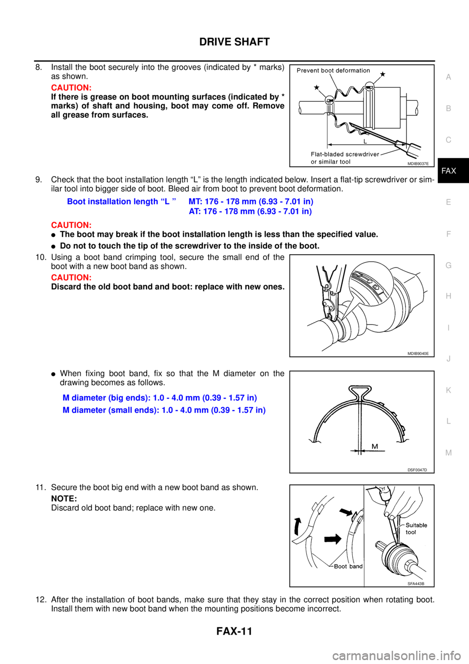
8. Install the boot securely into the grooves (indicated by * marks)
as shown.
CAUTION:
If there is grease on boot mounting surfaces (indicated by *
marks) of shaft and housing, boot may come off. Remove
all grease from surfaces.
9. Check that the boot installation length “L” is the length indicated below. Insert a flat-tip screwdriver or sim-
ilar tool into bigger side of boot. Bleed air from boot to prevent boot deformation.
CAUTION:
lThe boot may break if the boot installation length is less than the specified value.
lDo not to touch the tip of the screwdriver to the inside of the boot.
10. Usingabootbandcrimpingtool,securethesmallendofthe
boot with a new boot band as shown.
CAUTION:
Discard the old boot band and boot: replace with new ones.
lWhen fixing boot band, fix so that the M diameter on the
drawing becomes as follows.
11. Secure the boot big end with a new boot band as shown.
NOTE:
Discard old boot band; replace with new one.
12. After the installation of boot bands, make sure that they stay in the correct position when rotating boot.
Install them with new boot band when the mounting positions become incorrect.
MDIB9037E
Boot installation length “L ” MT: 176 - 178 mm (6.93 - 7.01 in)
AT: 176 - 178 mm (6.93 - 7.01 in)
MDIB9040E
M diameter (big ends): 1.0 - 4.0 mm (0.39 - 1.57 in)
M diameter (small ends): 1.0 - 4.0 mm (0.39 - 1.57 in)
DSF0047D
SFA443B
Page 1544 of 3171
FAX-12
DRIVE SHAFT
13. Install circlip and dust cover to housing.
NOTE:
Do not reuse circlip and dust cover.
Wheel Side
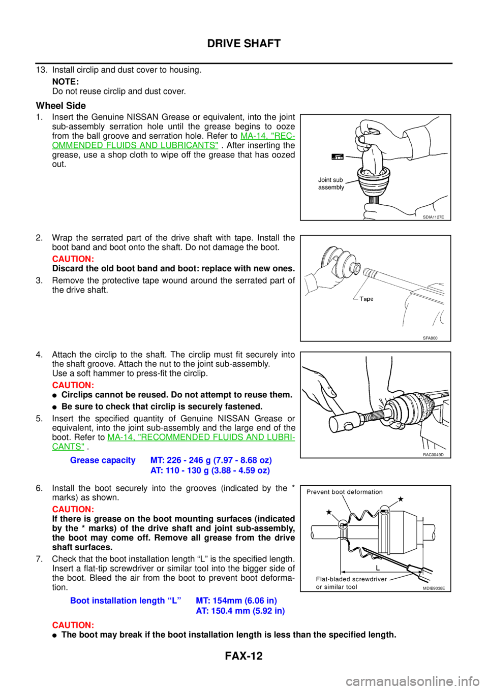
1. Insert the Genuine NISSAN Grease or equivalent, into the joint
sub-assembly serration hole until the grease begins to ooze
from the ball groove and serration hole. Refer toMA-14, "
REC-
OMMENDED FLUIDS AND LUBRICANTS". After inserting the
grease, use a shop cloth to wipe off the grease that has oozed
out.
2. Wrap the serrated part of the drive shaft with tape. Install the
boot band and boot onto the shaft. Do not damage the boot.
CAUTION:
Discard the old boot band and boot: replace with new ones.
3. Remove the protective tape wound around the serrated part of
the drive shaft.
4. Attach the circlip to the shaft. The circlip must fit securely into
the shaft groove. Attach the nut to the joint sub-assembly.
Useasofthammertopress-fitthecirclip.
CAUTION:
lCirclips cannot be reused. Do not attempt to reuse them.
lBe sure to check that circlip is securely fastened.
5. Insert the specified quantity of Genuine NISSAN Grease or
equivalent, into the joint sub-assembly and the large end of the
boot. Refer toMA-14, "
RECOMMENDED FLUIDS AND LUBRI-
CANTS".
6. Install the boot securely into the grooves (indicated by the *
marks) as shown.
CAUTION:
If there is grease on the boot mounting surfaces (indicated
by the * marks) of the drive shaft and joint sub-assembly,
the boot may come off. Remove all grease from the drive
shaft surfaces.
7. Check that the boot installation length “L” is the specified length.
Insert a flat-tip screwdriver or similar tool into the bigger side of
the boot. Bleed the air from the boot to prevent boot deforma-
tion.
CAUTION:
lThe boot may break if the boot installation length is less than the specified length.
SDIA1127E
SFA800
Grease capacity MT: 226 - 246 g (7.97 - 8.68 oz)
AT: 110 - 130 g (3.88 - 4.59 oz)RAC0049D
Boot installation length “L” MT: 154mm (6.06 in)
AT: 150.4 mm (5.92 in)
MDIB9038E
Page 1546 of 3171
FAX-14
SERVICE DATA AND SPECIFICATIONS (SDS)
SERVICE DATA AND SPECIFICATIONS (SDS)
PFP:00030
Wheel BearingEDS003IB
Drive ShaftEDS003IC
Wheel bearing axial end play 0.05 mm (0.002 in) or less
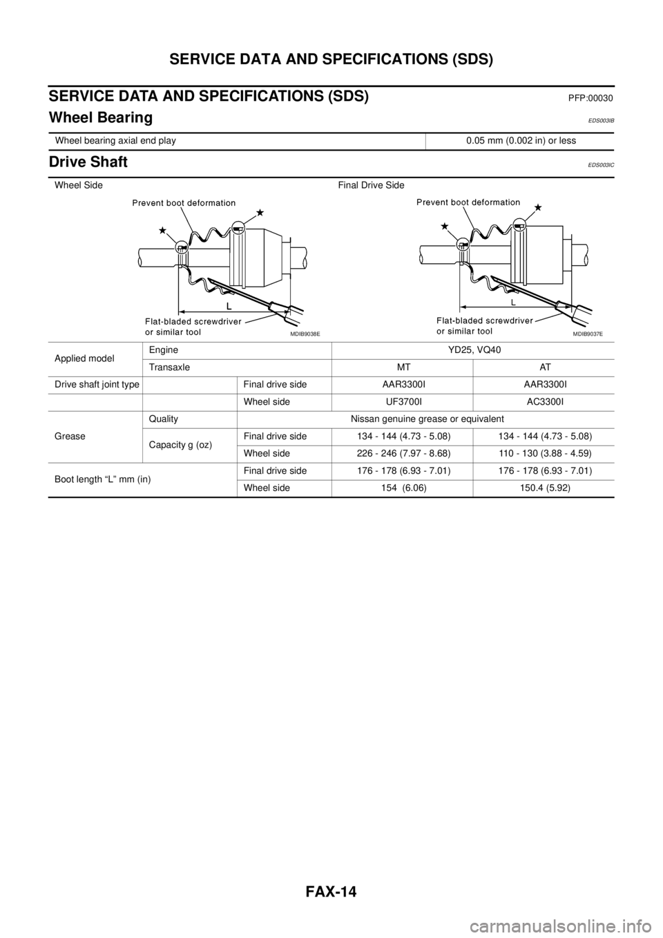
Wheel Side Final Drive Side
Applied modelEngine YD25, VQ40
Transaxle MT AT
Drive shaft joint type Final drive side AAR3300I AAR3300I
Wheel side UF3700I AC3300I
GreaseQuality Nissan genuine grease or equivalent
Capacity g (oz)Final drive side 134 - 144 (4.73 - 5.08) 134 - 144 (4.73 - 5.08)
Wheel side 226 - 246 (7.97 - 8.68) 110 - 130 (3.88 - 4.59)
Boot length “L” mm (in)Final drive side 176 - 178 (6.93 - 7.01) 176 - 178 (6.93 - 7.01)
Wheel side 154 (6.06) 150.4 (5.92)
MDIB9038EMDIB9037E
Page 1592 of 3171
FL-8
FUEL COOLER
INSTALLATION
Note the following, and install in the reverse order of removal.
lInsert hose to the length below when there is no spool on the fuel tube and surely clamp fuel hoses.
lBe sure hose clamp is not positioned on swelled area of fuel tube.
INSPECTION AFTER INSTALLATION
Make sure there is no fuel leakage at connections in the following steps.
lStart engine and rev it up and make sure there is no fuel leakage at connections.Fuel hose : 25 mm (0.98 in)
Page 1596 of 3171
FL-12
FUEL TANK
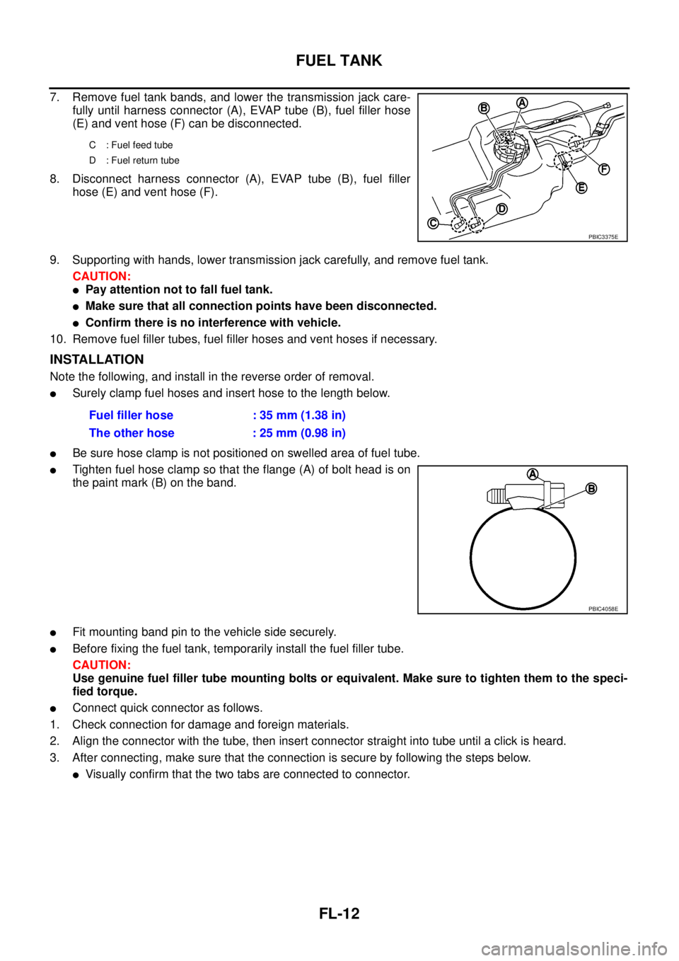
7. Remove fuel tank bands, and lower the transmission jack care-
fully until harness connector (A), EVAP tube (B), fuel filler hose
(E) and vent hose (F) can be disconnected.
8. Disconnect harness connector (A), EVAP tube (B), fuel filler
hose (E) and vent hose (F).
9. Supporting with hands, lower transmission jack carefully, and remove fuel tank.
CAUTION:
lPay attention not to fall fuel tank.
lMake sure that all connection points have been disconnected.
lConfirm there is no interference with vehicle.
10. Remove fuel filler tubes, fuel filler hoses and vent hoses if necessary.
INSTALLATION
Note the following, and install in the reverse order of removal.
lSurely clamp fuel hoses and insert hose to the length below.
lBe sure hose clamp is not positioned on swelled area of fuel tube.
lTighten fuel hose clamp so that the flange (A) of bolt head is on
the paint mark (B) on the band.
lFit mounting band pin to the vehicle side securely.
lBefore fixing the fuel tank, temporarily install the fuel filler tube.
CAUTION:
Use genuine fuel filler tube mounting bolts or equivalent. Make sure to tighten them to the speci-
fied torque.
lConnect quick connector as follows.
1. Check connection for damage and foreign materials.
2. Align the connector with the tube, then insert connector straight into tube until a click is heard.
3. After connecting, make sure that the connection is secure by following the steps below.
lVisually confirm that the two tabs are connected to connector.
C : Fuel feed tube
D : Fuel return tube
PBIC3375E
Fuel filler hose : 35 mm (1.38 in)
The other hose : 25 mm (0.98 in)
PBIC4058E
Page 1609 of 3171
ON-VEHICLE SERVICE
FSU-9
C
D
F
G
H
I
J
K
L
MA
B
FSU
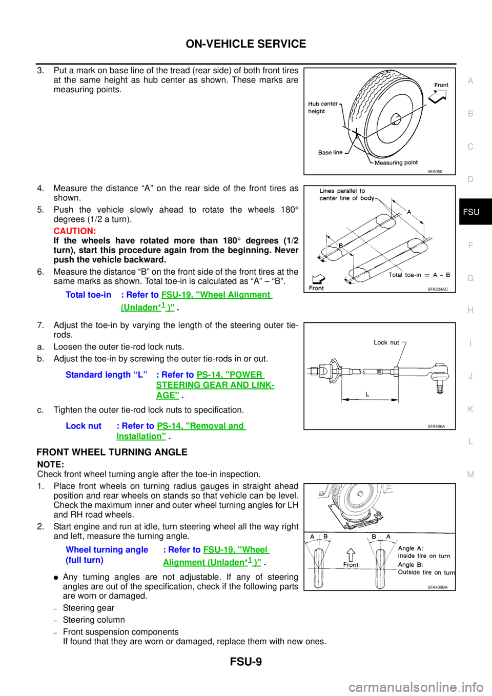
3. Put a mark on base line of the tread (rear side) of both front tires
at the same height as hub center as shown. These marks are
measuring points.
4. Measure the distance “A” on the rear side of the front tires as
shown.
5. Push the vehicle slowly ahead to rotate the wheels 180°
degrees (1/2 a turn).
CAUTION:
If the wheels have rotated more than 180°degrees (1/2
turn), start this procedure again from the beginning. Never
push the vehicle backward.
6. Measure the distance “B” on the front side of the front tires at the
same marks as shown. Total toe-in is calculated as “A” – “B”.
7. Adjust the toe-in by varying the length of the steering outer tie-
rods.
a. Loosen the outer tie-rod lock nuts.
b. Adjust the toe-in by screwing the outer tie-rods in or out.
c. Tighten the outer tie-rod lock nuts to specification.
FRONT WHEEL TURNING ANGLE
NOTE:
Check front wheel turning angle after the toe-in inspection.
1. Place front wheels on turning radius gauges in straight ahead
position and rear wheels on stands so that vehicle can be level.
Check the maximum inner and outer wheel turning angles for LH
and RH road wheels.
2. Start engine and run at idle, turn steering wheel all the way right
and left, measure the turning angle.
lAny turning angles are not adjustable. If any of steering
angles are out of the specification, check if the following parts
are worn or damaged.
–Steering gear
–Steering column
–Front suspension components
If found that they are worn or damaged, replace them with new ones.
AFA050
Total toe-in : Refer toFSU-19, "Wheel Alignment
(Unladen*1)".
SFA234AC
Standard length “L” : Refer toPS-14, "POWER
STEERING GEAR AND LINK-
AGE".
Lock nut : Refer toPS-14, "
Removal and
Installation".
SFA486A
Wheel turning angle
(full turn):RefertoFSU-19, "Wheel
Alignment (Unladen*1)".
SFA439BA
Page 1629 of 3171
PRECAUTIONS
GI-7
C
D
E
F
G
H
I
J
K
L
MB
GI
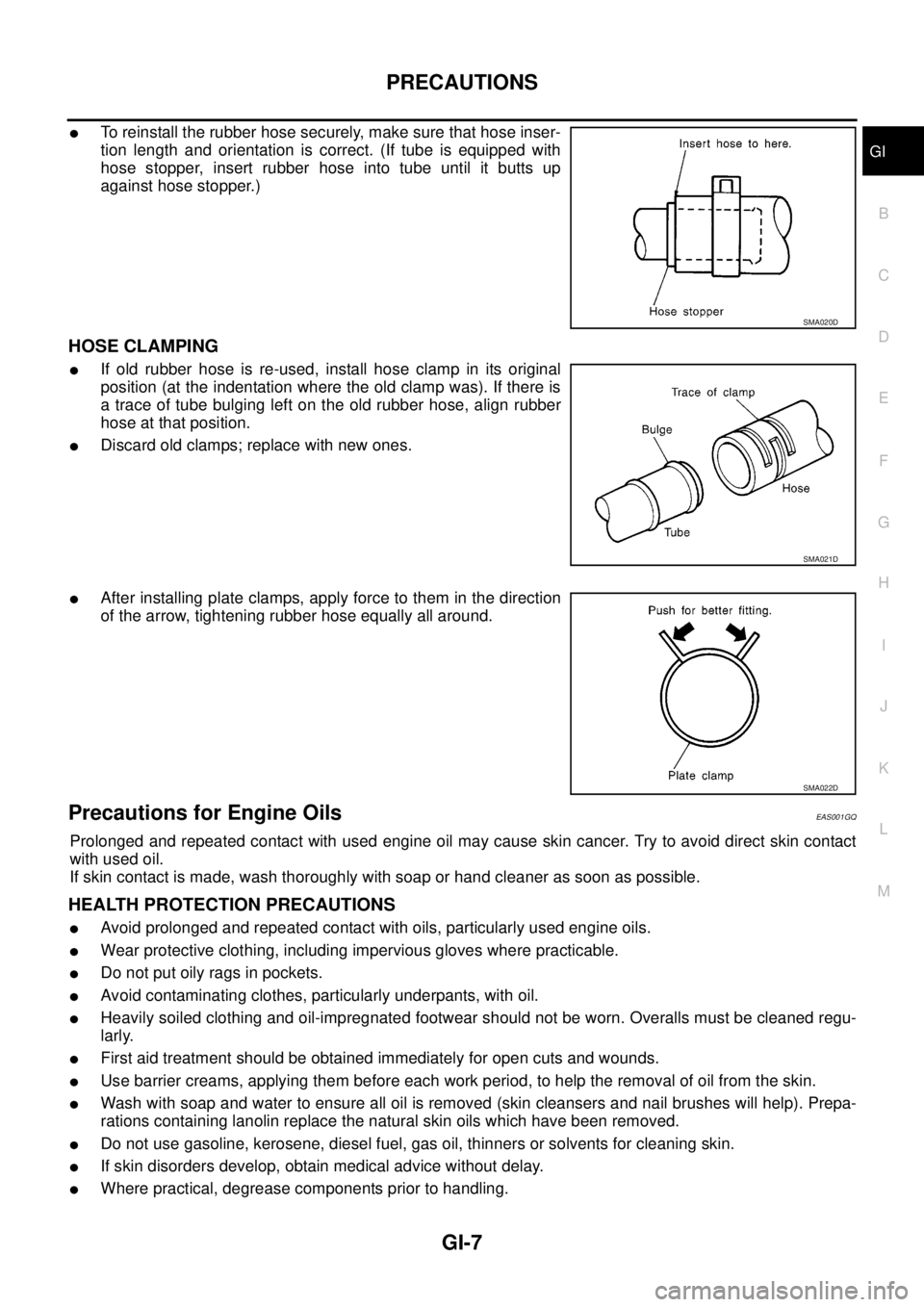
lTo reinstall the rubber hose securely, make sure that hose inser-
tion length and orientation is correct. (If tube is equipped with
hose stopper, insert rubber hose into tube until it butts up
against hose stopper.)
HOSE CLAMPING
lIf old rubber hose is re-used, install hose clamp in its original
position (at the indentation where the old clamp was). If there is
a trace of tube bulging left on the old rubber hose, align rubber
hose at that position.
lDiscard old clamps; replace with new ones.
lAfter installing plate clamps, apply force to them in the direction
of the arrow, tightening rubber hose equally all around.
Precautions for Engine OilsEAS001GQ
Prolonged and repeated contact with used engine oil may cause skin cancer. Try to avoid direct skin contact
with used oil.
If skin contact is made, wash thoroughly with soap or hand cleaner as soon as possible.
HEALTH PROTECTION PRECAUTIONS
lAvoid prolonged and repeated contact with oils, particularly used engine oils.
lWear protective clothing, including impervious gloves where practicable.
lDo not put oily rags in pockets.
lAvoid contaminating clothes, particularly underpants, with oil.
lHeavily soiled clothing and oil-impregnated footwear should not be worn. Overalls must be cleaned regu-
larly.
lFirst aid treatment should be obtained immediately for open cuts and wounds.
lUse barrier creams, applying them before each work period, to help the removal of oil from the skin.
lWash with soap and water to ensure all oil is removed (skin cleansers and nail brushes will help). Prepa-
rations containing lanolin replace the natural skin oils which have been removed.
lDo not use gasoline, kerosene, diesel fuel, gas oil, thinners or solvents for cleaning skin.
lIf skin disorders develop, obtain medical advice without delay.
lWhere practical, degrease components prior to handling.
SMA020D
SMA021D
SMA022D