2005 NISSAN NAVARA length
[x] Cancel search: lengthPage 2814 of 3171
LEAF SPRING
RSU-9
C
D
F
G
H
I
J
K
L
MA
B
RSU
INSPECTION AFTER REMOVAL
lCheck the rear leaf spring for any cracks or damage. Replace the rear leaf spring if necessary.
lCheck the rear spring shackle, rear spring clip U-bolts, bumper, and rear spring pad for excessive wear,
cracks, straightness, and damage. Replace any components if necessary.
lCheck all bushings for deformation and cracks. Replace any bushings if necessary.
INSTALLATION
1. Apply soapsuds to all of the rubber bushings.
2. Install the rear spring shackle and rear leaf spring front nut and bolt. Finger-tighten the nuts.
3. Install the rear spring clip U-bolts and bumper on top of the rear leaf spring.
4. Install the rear spring pad, and nuts under the axle case.
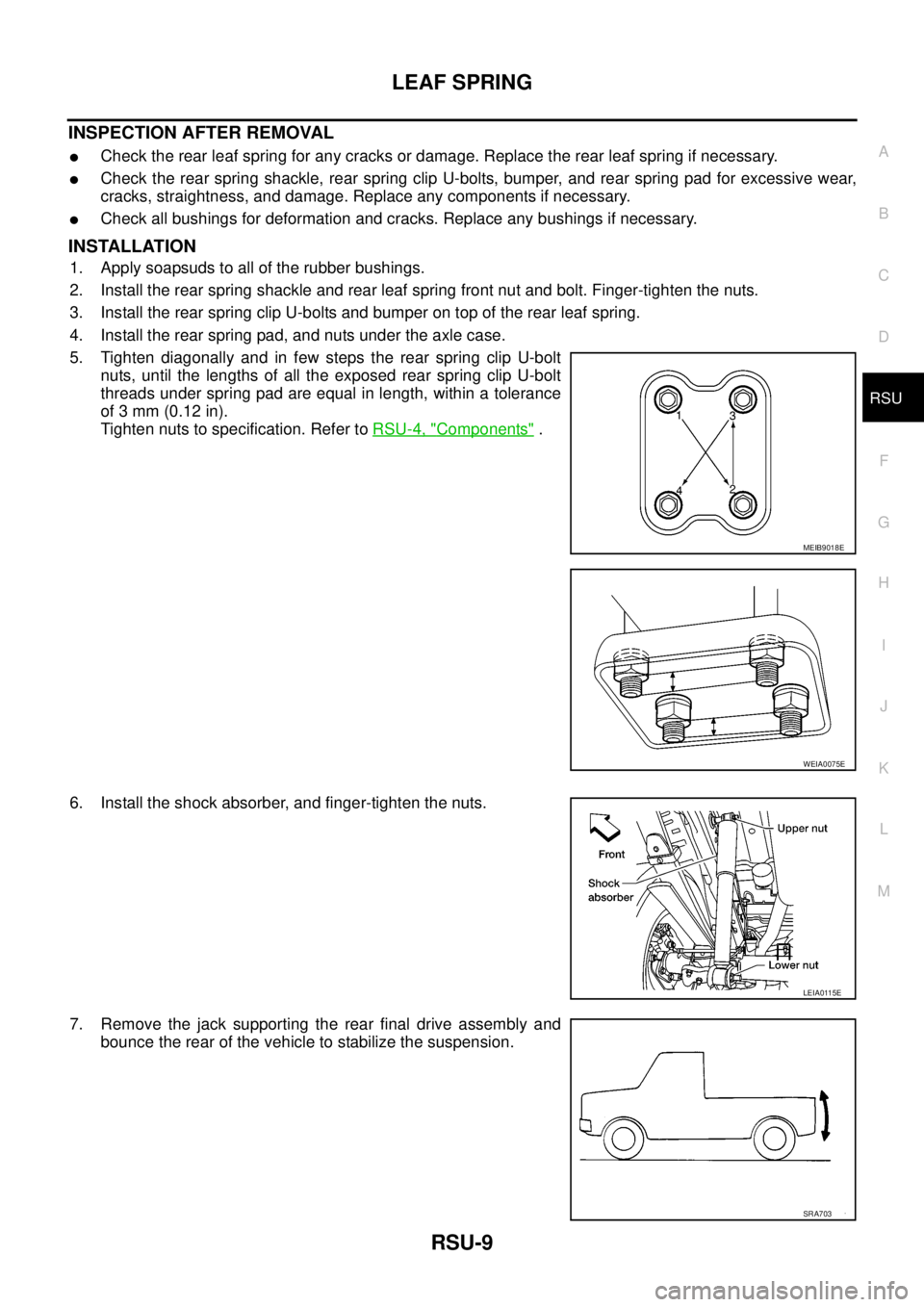
5. Tighten diagonally and in few steps the rear spring clip U-bolt
nuts, until the lengths of all the exposed rear spring clip U-bolt
threads under spring pad are equal in length, within a tolerance
of 3 mm (0.12 in).
Tighten nuts to specification. Refer toRSU-4, "
Components".
6. Install the shock absorber, and finger-tighten the nuts.
7. Remove the jack supporting the rear final drive assembly and
bounce the rear of the vehicle to stabilize the suspension.
MEIB9018E
WEIA0075E
LEIA0115E
SRA703
Page 2828 of 3171
SEAT BELTS
SB-11
C
D
E
F
G
I
J
K
L
MA
B
SB
Seat Belt InspectionEHS0026A
AFTER A COLLISION
WARNING:
Inspect all seat belt assemblies including retractors and attaching hardware after any collision.
NISSAN recommends that all seat belt assemblies in use during a collision be replaced unless the col-
lision was minor and the belts show no damage and continue to operate properly. Failure to do so
could result in serious personal injury in an accident. Seat belt assemblies not in use during a colli-
sion should also be replaced if either damage or improper operation is noted. Seat belt pre-tensioners
should be replaced even if the seat belts are not in use during a frontal collision in which the air bags
are deployed.
Replace any seat belt assembly (including anchor bolts) if:
lThe seat belt was in use at the time of a collision (except for minor collisions and the belts, retractors and
buckles show no damage and continue to operate properly).
lThe seat belt was damaged in an accident. (i.e. torn webbing, bent retractor or guide).
lThe seat belt attaching point was damaged in an accident. Inspect the seat belt attaching area for damage
or distortion and repair as necessary before installing a new seat belt assembly.
lAnchor bolts are deformed or worn out.
lThe seat belt pre-tensioner should be replaced even if the seat belts are not in use during the collision in
which the air bags are deployed.
PRELIMINARY CHECKS
1. Check the seat belt warning lamp for proper operation as follows:
a. Switch ignition ON. The seat belt warning lamp should illuminate.
b. Fasten driver's seat belt. The seat belt warning lamp should go out. If warning lamp remains illuminated,
Refer toDI-28, "
WARNING LAMPS".
2. If the air bag warning lamp is blinking, conduct self-diagnosis using CONSULT-II, and air bag warning
lamp. Refer toSRS-18, "
SRS Operation Check".
3. Check that the seat belt retractor, seat belt anchor and buckle bolts are securely attached.
4. Check the shoulder seat belt guide and shoulder belt height adjuster for front seats. Ensure guide swivels
freely and that belt lays flat and does not bind in guide. Ensure height adjuster operates properly and
holds securely.
5. Check retractor operation:
a. Fully extend the seat belt webbing and check for twists, tears or other damage.
b. Allow the seat belt to retract. Ensure that belt returns smoothly and completely into the retractor. If the
seat belt does not return smoothly, wipe the inside of the loops with a clean paper cloth, because dirt built
up in the loops of the upper anchors can cause the seat belts to retract slowly.
c. Fasten the seat belt. Check the seat belt returns smoothly and completely to the retractor. If the belt does
not return smoothly, the cause may be an accumulation of dust or dirt. Use the “SEAT BELT TAPE SET”
and perform the following steps.
Inspect the front seat belt through-anchor:
1. Pull the seat belt out to a length of 500 mm (19.69 in) or more.
2. Use a clip or other device to hold the seat belt at the center pillar belt opening.
3. Pass a thin wire through the through-anchor belt opening. Hold both ends of the wire and pull taut while
moving it up and down several times along the belt opening surface to remove dirt.
4. Any dirt that cannot be removed with the wire can be removed by cleaning the opening with a clean
cloth.
5. Apply tape at the point where the belt contacts the through-anchor belt opening.
NOTE:
Apply the tape so that there is no looseness or wrinkling.
6. Remove the clip holding the seat belt and check that the belt returns smoothly.
7. Repeat steps above as necessary to check the other seat belts.
Page 2834 of 3171
SC-1
STARTING & CHARGING SYSTEM
K ELECTRICAL
CONTENTS
C
D
E
F
G
H
I
J
L
M
SECTIONSC
A
B
SC
STARTING & CHARGING SYSTEM
PRECAUTIONS .......................................................... 3
Precautions for Supplemental Restraint System
(SRS)“AIRBAG”and“SEATBELTPRE-TEN-
SIONER” .................................................................. 3
Wiring Diagrams and Trouble Diagnosis .................. 3
PREPARATION ........................................................... 4
Special Service Tools ............................................... 4
BATTERY .................................................................... 5
How to Handle Battery ............................................. 5
METHODS OF PREVENTING OVER-DIS-
CHARGE ............................................................... 5
CHECKING ELECTROLYTE LEVEL .................... 5
SPECIFIC GRAVITY CHECK ............................... 6
Battery Test and Charging Chart .............................. 7
CHART I ................................................................ 7
CHART II ............................................................... 8
A: SLOW CHARGE ............................................... 9
B: STANDARD CHARGE .................................... 10
C: QUICK CHARGE ............................................ 12
Removal and Installation ........................................ 13
CHARGING SYSTEM ............................................... 14
System Description ................................................ 14
Wiring Diagram — CHARGE — ............................. 15
Trouble Diagnosis .................................................. 16
DIAGNOSIS PROCEDURE ................................ 16
PRE-DIAGNOSIS INSPECTION ......................... 16
DIAGNOSIS CHART BY SYMPTOM .................. 16
INSPECTION FLOW BY CHARGE WARNING
LAMP .................................................................. 16
CHARGE WARNING LAMP LINE INSPECTION... 17
VOLTAGE DETECTION LINE AND CHARGE
WARNING LAMP INSPECTION ......................... 18
INSPECTION OF INSUFFICIENT ALTERNA-
TOR POWER GENERATION .............................. 20
INSPECTION OF EXCESSIVE ALTERNATOR
POWER GENERATION ...................................... 20
DARK CURRENT INSPECTION ......................... 21
OPERATION PROCEDURE OF CURRENT
MEASUREMENT PROBE FOR CONSULT-II ..... 22
Removal and Installation ........................................ 23REMOVAL ........................................................... 23
INSTALLATION ................................................... 23
Disassembly and Assembly .................................... 23
LHD MODELS ..................................................... 23
RHD MODELS .................................................... 24
Disassembly ........................................................... 24
REAR COVER ..................................................... 24
REAR BEARING ................................................. 24
Inspection ............................................................... 25
ROTOR CHECK .................................................. 25
BRUSH CHECK .................................................. 25
PULLEY CHECK (WITH CLUTCH TYPE) ........... 25
STATOR CHECK ................................................. 25
Assembly ................................................................ 26
RING FITTING IN REAR BEARING .................... 26
REAR COVER INSTALLATION ........................... 26
STARTING SYSTEM ................................................. 27
System Description ................................................. 27
A/T MODELS ....................................................... 27
M/T MODELS ...................................................... 27
Wiring Diagram — START — ................................. 28
A/T MODELS ....................................................... 28
M/T MODELS ...................................................... 29
Trouble Diagnoses ................................................. 30
Removal and Installation ........................................ 31
REMOVAL ........................................................... 31
INSTALLATION ................................................... 31
Disassembly and Assembly .................................... 32
Inspection ............................................................... 32
MAGNETIC SWITCH CHECK ............................. 32
PINION/CLUTCH CHECK ................................... 33
BRUSH CHECK .................................................. 33
YOKE CHECK ..................................................... 34
ARMATURE CHECK ........................................... 35
Assembly ................................................................ 36
PINION PROTRUSION LENGTH ADJUST-
MENT .................................................................. 36
SERVICE DATA AND SPECIFICATIONS (SDS) ...... 37
Battery .................................................................... 37
Page 2866 of 3171
STARTING SYSTEM
SC-33
C
D
E
F
G
H
I
J
L
MA
B
SC
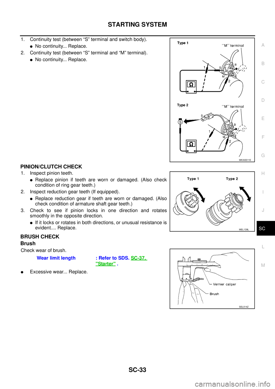
1. Continuity test (between “S” terminal and switch body).
lNo continuity... Replace.
2. Continuity test (between “S” terminal and “M” terminal).
lNo continuity... Replace.
PINION/CLUTCH CHECK
1. Inspect pinion teeth.
lReplace pinion if teeth are worn or damaged. (Also check
condition of ring gear teeth.)
2. Inspect reduction gear teeth (If equipped).
lReplace reduction gear if teeth are worn or damaged. (Also
check condition of armature shaft gear teeth.)
3. Check to see if pinion locks in one direction and rotates
smoothly in the opposite direction.
lIf it locks or rotates in both directions, or unusual resistance is
evident.... Replace.
BRUSH CHECK
Brush
Check wear of brush.
lExcessive wear... Replace.
MKIA0011E
MEL139L
Wear limit length : Refer to SDS.SC-37,
"Starter".
SEL014Z
Page 2869 of 3171
SC-36
STARTING SYSTEM
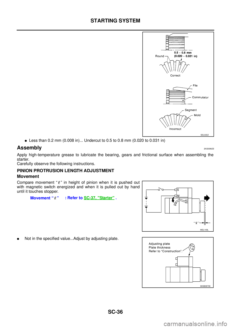
lLess than 0.2 mm (0.008 in)... Undercut to 0.5 to 0.8 mm (0.020 to 0.031 in)
AssemblyEKS00MZS
Apply high-temperature grease to lubricate the bearing, gears and frictional surface when assembling the
starter.
Carefully observe the following instructions.
PINION PROTRUSION LENGTH ADJUSTMENT
Movement
Compare movement “ ” in height of pinion when it is pushed out
with magnetic switch energized and when it is pulled out by hand
until it touches stopper.
lNot in the specified value...Adjust by adjusting plate.
SEL022Z
Movement “ ”:RefertoSC-37, "Starter".
MEL140L
MKIB0870E
Page 2870 of 3171
SERVICE DATA AND SPECIFICATIONS (SDS)
SC-37
C
D
E
F
G
H
I
J
L
MA
B
SC
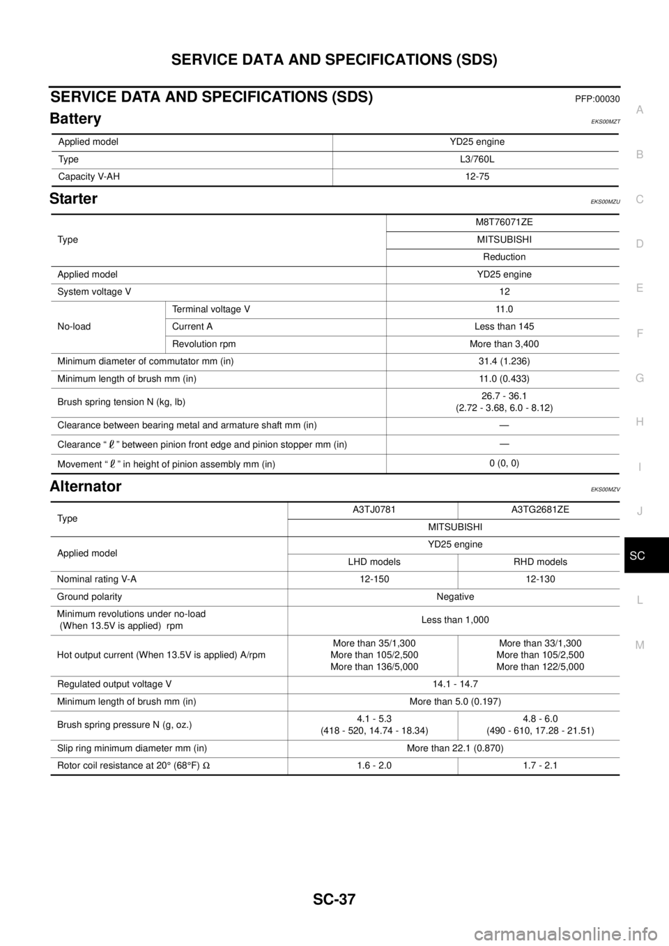
SERVICE DATA AND SPECIFICATIONS (SDS)PFP:00030
BatteryEKS00MZT
StarterEKS00MZU
AlternatorEKS00MZV
Applied modelYD25 engine
TypeL3/760L
Capacity V-AH12-75
Ty p eM8T76071ZE
MITSUBISHI
Reduction
Applied modelYD25 engine
System voltage V12
No-loadTerminal voltage V 11.0
Current A Less than 145
Revolution rpm More than 3,400
Minimum diameter of commutator mm (in) 31.4 (1.236)
Minimum length of brush mm (in) 11.0 (0.433)
Brush spring tension N (kg, lb)26.7 - 36.1
(2.72 - 3.68, 6.0 - 8.12)
Clearance between bearing metal and armature shaft mm (in) —
Clearance “ ” between pinion front edge and pinion stopper mm (in)—
Movement “ ” in height of pinion assembly mm (in)0 (0, 0)
TypeA3TJ0781 A3TG2681ZE
MITSUBISHI
Applied modelYD25 engine
LHD models RHD models
Nominal rating V-A 12-150 12-130
Ground polarityNegative
Minimum revolutions under no-load
(When 13.5V is applied) rpmLess than 1,000
Hot output current (When 13.5V is applied) A/rpmMore than 35/1,300
More than 105/2,500
More than 136/5,000More than 33/1,300
More than 105/2,500
More than 122/5,000
Regulated output voltage V 14.1 - 14.7
Minimum length of brush mm (in) More than 5.0 (0.197)
Brush spring pressure N (g, oz.)4.1 - 5.3
(418 - 520, 14.74 - 18.34)4.8 - 6.0
(490 - 610, 17.28 - 21.51)
Slip ring minimum diameter mm (in) More than 22.1 (0.870)
Rotor coil resistance at 20°(68°F)W1.6 - 2.0 1.7 - 2.1
Page 3079 of 3171
TF-112
TRANSFER ASSEMBLY
INSTALLATION
Note the following, and install in the reverse order of removal.
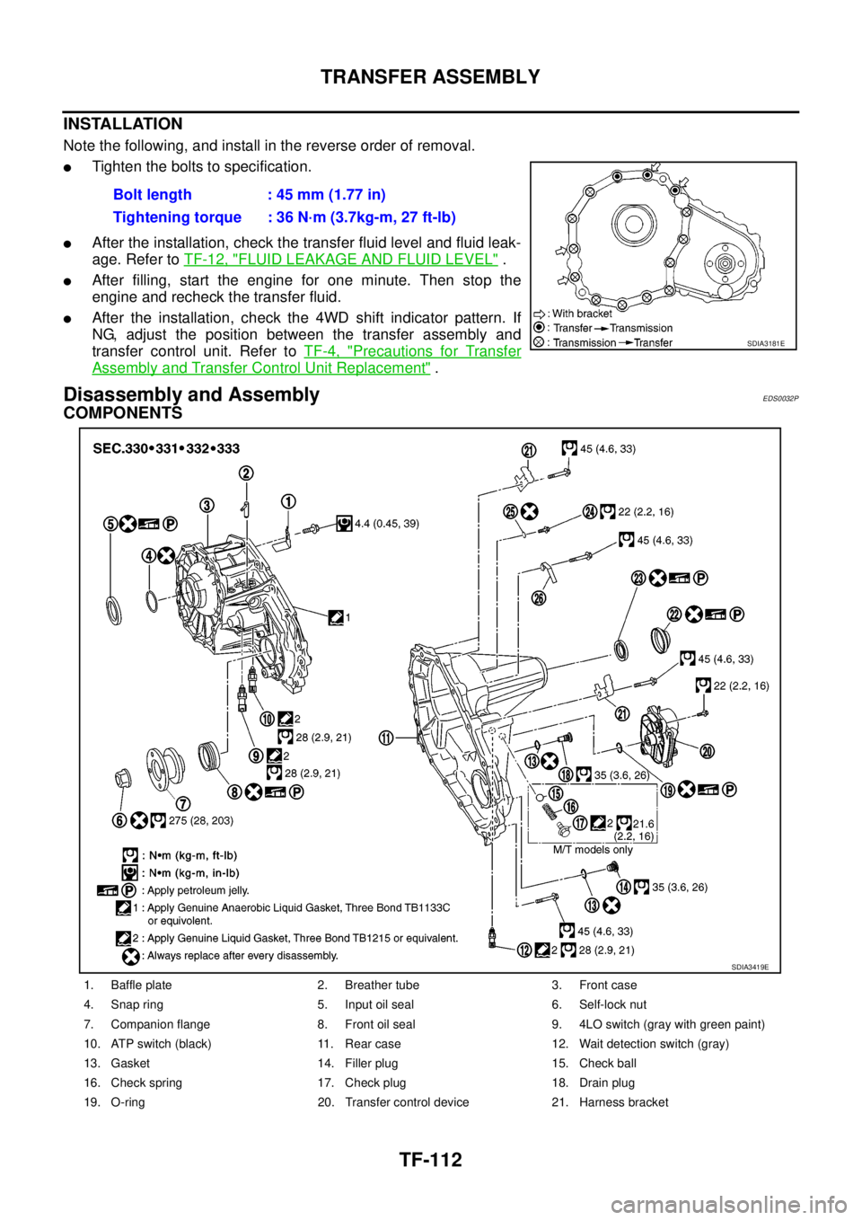
lTighten the bolts to specification.
lAfter the installation, check the transfer fluid level and fluid leak-
age. Refer toTF-12, "
FLUID LEAKAGE AND FLUID LEVEL".
lAfter filling, start the engine for one minute. Then stop the
engine and recheck the transfer fluid.
lAfter the installation, check the 4WD shift indicator pattern. If
NG, adjust the position between the transfer assembly and
transfer control unit. Refer toTF-4, "
Precautions for Transfer
Assembly and Transfer Control Unit Replacement".
Disassembly and AssemblyEDS0032P
COMPONENTS
Bolt length : 45 mm (1.77 in)
Tightening torque : 36 N·m (3.7kg-m, 27 ft-lb)
SDIA3181E
1. Baffle plate 2. Breather tube 3. Front case
4. Snap ring 5. Input oil seal 6. Self-lock nut
7. Companion flange 8. Front oil seal 9. 4LO switch (gray with green paint)
10. ATP switch (black) 11. Rear case 12. Wait detection switch (gray)
13. Gasket 14. Filler plug 15. Check ball
16. Check spring 17. Check plug 18. Drain plug
19. O-ring 20. Transfer control device 21. Harness bracket
SDIA3419E