2005 NISSAN NAVARA length
[x] Cancel search: lengthPage 1682 of 3171

GI-60
IDENTIFICATION INFORMATION
Dimensions
EAS001DO
KING CAB
Unit: mm (in)
DOUBLE CAB
Unit: mm (in)
Wheels & TyresEAS001DP
Drive Type 2WD 4WD
Tyre size 235/70R16 255/70R16 235/70R16 255/70R16 265/70R16 255/65R17
Overall length 5220 (205.5)
Overall width 1850 (72.8)
Overall height 1743 (68.6) 1756 (69.1) 1751 (68.9) 1766 (69.5) 1777 (70.0) 1771 (69.7)
Front tread width
1570 (61.8)
Rear tread width
Wheelbase 3200 (126.0)
Drive Type 2WD 4WD
Tyre size 255/70R16 255/65R17 235/70R16 255/70R16 265/70R16 255/65R17
Overall length 5220 (205.5)
Overall width 1850 (72.8)
Overall height
(with Roof Rack)1881 (74.1) 1885 (74.2) 1873 (73.7) 1888 (74.3) 1899 (74.8) 1893 (74.5)
Overall height
(without Roof Rack)1771 (69.7) 1775 (69.9) 1764 (69.4) 1779 (70.0) 1789 (70.4) 1784 (70.2)
Front tread width
1570 (61.8)
Rear tread width
Wheelbase 3200 (126.0)
Drive Type Road wheel Tyre Spare tyre size
All16 X 7J Steel 235/70R16 235/70R16
16 X 7J Aluminum Alloy235/70R16 235/70R16
255/70R16 255/70R16
17 X 7J Aluminum Alloy 255/65R17 255/65R17
Page 1757 of 3171
IDX-5
A
C
D
E
F
G
H
I
J
K
L B
IDX
ALPHABETICAL INDEX
HSEAT - Wiring diagram .......................SE-14,SE-17
I
IATS - Wiring diagram .....................................EC-100
Identification plate ...............................................GI-57
Idle speed ..........................................................EC-38
Ignition key hole illumination .............................LT-145
ILL - Wiring diagram .........................................LT-166
Illumination .......................................................LT-162
In vehicle sensor ...........................ATC-108,ATC-118
INJE/PW - Wiring diagram ...............................EC-284
INJECT - Wiring diagram .....EC-128,EC-240,EC-289
Injection nozzle .......EM-44,EC-123,EC-125,EC-237
Injector adjustment value ...................EC-271,EC-273
Injector adjustment value registration ................EC-25
Input clutch solenoid valve .................AT-132,AT-134
Instrument panel ..................................................IP-10
INT/V - Wiring diagram ....................................EC-315
Intake air control valve control solenoid valve .EC-314
Intake air temperature sensor ............................EC-98
Intake door control linkage adjustment ............ATC-79
Intake door motor ..........ATC-77,ATC-129,MTC-109
Intake manifold ..................................................EM-20
Intake sensor ..ATC-114,ATC-120,MTC-95,MTC-99
Interior .................................................................EI-33
Interior lamp ......................................................LT-145
Interior lamp on-off control ................................LT-145
IPDM (Intelligent power distribution module engine
room) .................................................................PG-14
ISO 15031-2 Terminology ..................................GI-61
J
Jacking points .....................................................GI-52
K
Key illumination ................................................LT-145
KEYLES - Wiring diagram ..................................BL-93
L
Leaf spring (rear) ..............................................RSU-7
Length (Dimensions) ..........................................GI-60
License lamp ....................................................LT-125
Lifting points .......................................................GI-52
Line pressure solenoid valve ...........................AT-114
Line pressure test (A/T) .....................................AT-44
Liquid gasket application ................EM-5,LU-2,CO-2
Location of electrical units .................................PG-71
Low coast brake solenoid valve ..........AT-152,AT-154
Lubricant (R134a) A/C ......................ATC-24,MTC-24
Lubricants ..........................................................MA-14
Lubrication circuit (engine) ..................................LU-4
Lubrication oil A/C ............................ATC-24,MTC-24
Lubrication-locks, hinges and hood latches .......MA-39
M
MAFS - Wiring diagram .....................................EC-94
Magnet clutch .ATC-87,ATC-143,MTC-79,MTC-123
MAIN - Wiring diagram ......................................EC-72
Main drive gear (M/T) ........................................MT-21
Mainshaft (M/T) ..................................................MT-21
Major overhaul (Final drive)FFD-17,RFD-15,RFD-82
Major overhaul (Transfer) ................................TF-112
Malfunction indicator (MI) ..................................EC-28
Map lamp ..........................................................LT-145
Mass air flow sensor (MAFS) .............................EC-92
Master cylinder (brake) ......................................BR-17
Master cylinder (clutch) ........................................CL-9
Meter .....................................................................DI-4
METER - Wiring diagram ....................................DI-10
MI & data link connectors circuit ......................EC-354
MIL/DL - Wiring diagram ..................................EC-354
Mode door control linkage adjustment ............ATC-65,
MTC-59
Mode door motor ............ATC-63,ATC-130,MTC-58,
MTC-110
Model variation ...................................................GI-56
Multiport fuel injection precautions .......................GI-6
N
NATS - Wiring diagram ....................................BL-173
NATS (Nissan anti-theft system) precautions .......GI-3
NVH troubleshooting (AX) .................................FAX-4
NVH troubleshooting (BR) ...................................BR-5
NVH troubleshooting (EM) ................................EM-10
NVH troubleshooting (Final drive) ........FFD-6,RFD-7,
RFD-39
NVH troubleshooting (M/T) ..................................MT-6
NVH troubleshooting (Propeller shaft) .................PR-2
NVH troubleshooting (ST) ....................................PS-5
NVH troubleshooting (Transfer) .........................TF-11
NVH troubleshooting (WT)NVH troubleshooting (WT) .
WT-2
O
Oil cooler (engine) .............................................LU-11
Oil filter .................................................................LU-8
Oil pan (engine) ................................................EM-36
Oil pressure (engine) ...........................................LU-5
Oil pump (A/T) .................................................AT-281
Oil pump (engine) ..............................................LU-14
Oil seal replacement (engine) ...........................EM-70
Oil seal replacement (front of final drive) ...........FFD-9
Oil seal replacement (side of final drive) ..........FFD-13
On board diagnostic system ..............................EC-27
Operating cylinder (clutch) .................................CL-11
Overheat ..........................................................EC-132
Oversize piston ...............................................EM-129
Page 2089 of 3171

LT-6
HEADLAMP -CONVENTIONAL TYPE-
lto combination meter terminal 16.
Ground is supplied at all times
lto BCM terminal 55 and
lto combination meter terminal 23
lthrough grounds M21, M80 and M83,
lto IPDM E/R terminals 38 and 59
lthrough grounds E21, E41 and E61.
Low Beam Operation
With the lighting switch in 2ND position, the BCM receives input requesting the headlamps to illuminate. This
input is communicated to the IPDM E/R through the CAN communication. The CPU of the IPDM E/R controls
the headlamp low relay coil. When energized, this relay directs power
lthrough 15A fuse (No. 41, located in IPDM E/R)
lthrough IPDM E/R terminal 54
lto front combination lamp RH terminal 1,
lthrough 15A fuse (No. 40, located in IPDM E/R)
lthrough IPDM E/R terminal 52
lto front combination lamp LH terminal 1.
Ground is supplied
lto front combination lamp RH and LH terminals 3
lthrough grounds E21, E41 and E61.
With power and ground supplied, low beam headlamps illuminate.
High Beam Operation/Flash-to-Pass Operation
With the lighting switch in 2ND position and placed in HIGH or PASS position, the BCM receives input request-
ing the headlamp high beams to illuminate. This input is communicated to the IPDM E/R through the CAN
communication. The CPU of the IPDM E/R controls the headlamp high relay coil. When energized, this relay
directs power
lthrough 10A fuse (No. 34, located in IPDM E/R)
lthrough IPDM E/R terminal 56
lto front combination lamp RH terminal 2,
lthrough 10A fuse (No. 35, located in IPDM E/R)
lthrough IPDM E/R terminal 55
lto front combination lamp LH terminal 2.
Ground is supplied
lto front combination lamp RH and LH terminals 3
lthrough grounds E21, E41 and E61.
With power and ground supplied, the high beam headlamps illuminate.
Combination meter that received high beam request signal by BCM through the CAN communication makes a
high beam indicator lamp turn on in combination meter.
FRIENDLY LIGHTING FUNCTION
This function starts timer function of BCM by operating passing switch, and illuminates headlamps (LOW
beam) for a given length of time.
Headlamps (LOW beam) stay ON for a given length of time by operating passing switch when ignition switch is
OFF and lighting switch is OFF.
Headlamps (LOW beam) stays ON for two minutes at a maximum by operating passing switch repeatedly.
CONSULT-II is capable of setting a lighting time. Refer toLT- 1 6 , "
WORK SUPPORT".
CAN Communication System DescriptionEKS00P7J
Refer toLAN-23, "CAN COMMUNICATION".
Page 2335 of 3171
MT-18
TRANSMISSION ASSEMBLY
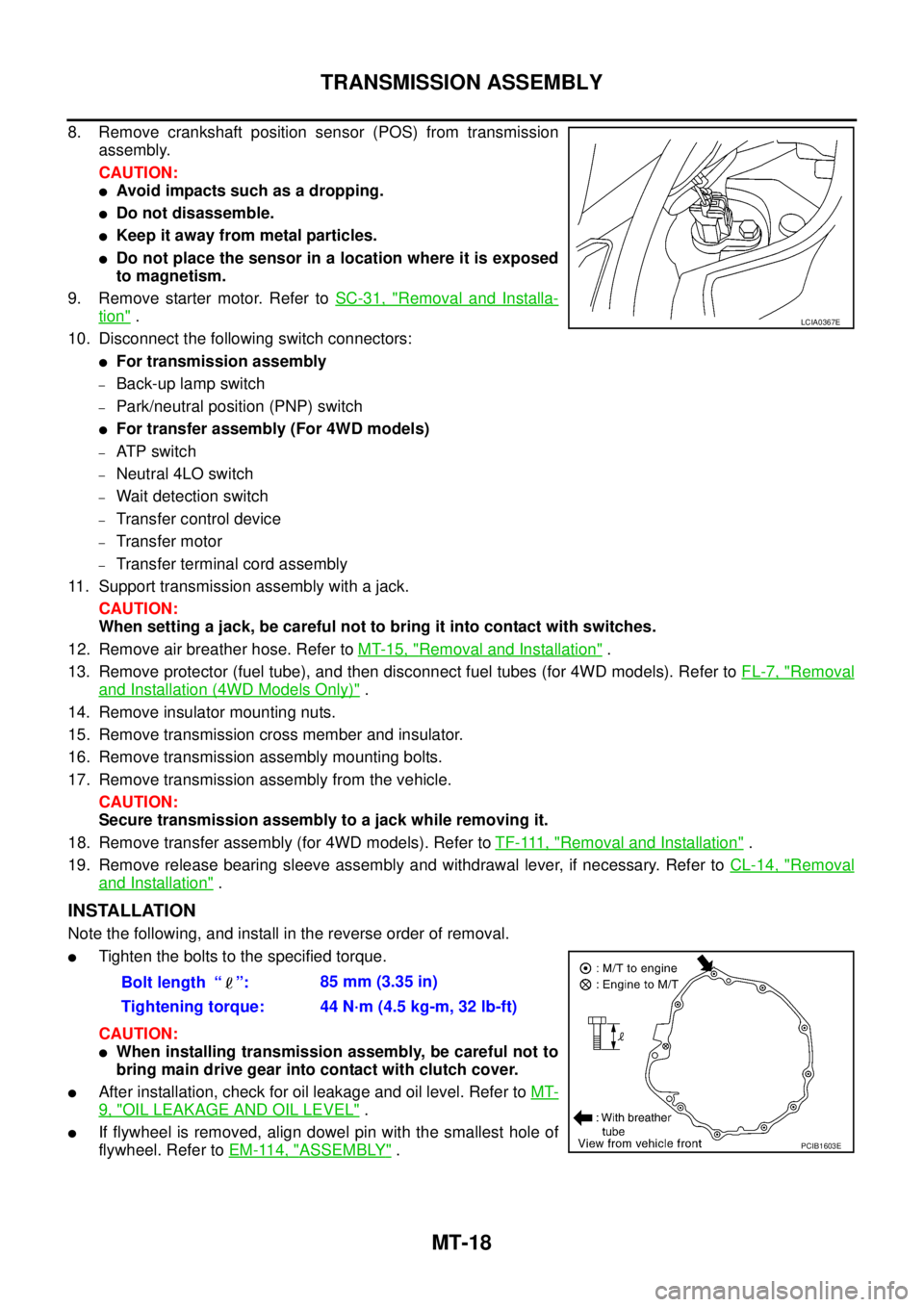
8. Remove crankshaft position sensor (POS) from transmission
assembly.
CAUTION:
lAvoid impacts such as a dropping.
lDo not disassemble.
lKeep it away from metal particles.
lDo not place the sensor in a location where it is exposed
to magnetism.
9. Remove starter motor. Refer toSC-31, "
Removal and Installa-
tion".
10. Disconnect the following switch connectors:
lFor transmission assembly
–Back-up lamp switch
–Park/neutral position (PNP) switch
lFor transfer assembly (For 4WD models)
–AT P s w i t c h
–Neutral 4LO switch
–Wait detection switch
–Transfer control device
–Transfer motor
–Transfer terminal cord assembly
11. Support transmission assembly with a jack.
CAUTION:
When setting a jack, be careful not to bring it into contact with switches.
12. Remove air breather hose. Refer toMT-15, "
Removal and Installation".
13. Remove protector (fuel tube), and then disconnect fuel tubes (for 4WD models). Refer toFL-7, "
Removal
and Installation (4WD Models Only)".
14. Remove insulator mounting nuts.
15. Remove transmission cross member and insulator.
16. Remove transmission assembly mounting bolts.
17. Remove transmission assembly from the vehicle.
CAUTION:
Secure transmission assembly to a jack while removing it.
18. Remove transfer assembly (for 4WD models). Refer toTF-111, "
Removal and Installation".
19. Remove release bearing sleeve assembly and withdrawal lever, if necessary. Refer toCL-14, "
Removal
and Installation".
INSTALLATION
Note the following, and install in the reverse order of removal.
lTighten the bolts to the specified torque.
CAUTION:
lWhen installing transmission assembly, be careful not to
bring main drive gear into contact with clutch cover.
lAfter installation, check for oil leakage and oil level. Refer toMT-
9, "OIL LEAKAGE AND OIL LEVEL".
lIf flywheel is removed, align dowel pin with the smallest hole of
flywheel. Refer toEM-114, "
ASSEMBLY".
LCIA0367E
Bolt length “ ”:85 mm (3.35 in)
Tightening torque: 44 N·m (4.5 kg-m, 32 lb-ft)
PCIB1603E
Page 2627 of 3171

PR-12
SERVICE DATA AND SPECIFICATIONS (SDS)
SERVICE DATA AND SPECIFICATIONS (SDS)
PFP:00030
General SpecificationsEDS0035N
2WD Models
4WD Models
Snap RingEDS0035O
Model 2S1330
Unit: mm (in)
*Always check with the Parts Department for the latest parts information.
Model 2F S1300 and 3S S1310
Unit: mm (in)
*Always check with the Parts Department for the latest parts information.Applied modelYD25DDTi
6M/T 5A/T
Propeller shaft model 3S S1310
Number of joints3
Coupling method with rear final drive Flange type
Coupling method with transmission Sleeve type
1st Shaft length (Center bearing to spider) 675 mm (26.57 in) 742 mm (29.21 in)
2nd Shaft length (Spider to spider) 897 mm (35.31 in)
Shaft outer diameter 75.64 mm (2.9779 in)
Journal axial play 0.02 mm (0.0008 in) or less
Propeller shaft run out limit 0.6 mm (0.024 in) or less
Propeller shaft joint flex effort 1.96 N·m (0.20 kg-m, 17 in-lb) or less
Applied modelYD25DDTi
Propeller shaft modelFront Rear
2F S1300 2S1330 (aluminum tube)
Number of joints2
Coupling method with front final drive Flange type
Coupling method with transfer Flange type Sleeve type
Shaft length (Spider to spider) 718 mm (28.27 in) 1266.8 mm (35.51 in)
Shaft outer diameter 65 mm (2.56 in) 102.5 mm (2.97 in)
Journal axial play 0.02 mm (0.0008 in) or less
Propeller shaft run out limit 0.6 mm (0.024 in) or less 1.02 mm (0.0402 in) or less
Propeller shaft joint flex effort 1.96 N·m (0.20 kg-m, 17 in-lb) or less 2.26 N·m (0.23 kg-m, 20 in-lb) or less
Thickness Part number* Thickness Part number*
1.600 - 1.638 (0.0630 - 0.0645)
1.549 - 1.588 (0.0610 - 0.0625)37146-7S000
37147-7S0001.524 - 1.562 (0.0600 - 0.0615)
1.499 - 1.537 (0.0590 - 0.0605)37148-7S000
37149-7S000
Thickness Part number* Thickness Part number*
1.45 (0.0571)
1.50 (0.0591)
1.55 (0.0610)
1.60 (0.0630)37146 7F000
37147 7F000
37148 7F000
37149 7F0001.65 (0.0650)
1.70 (0.0669)
1.75 (0.0689)37150 7F000
37151 7F000
37152 7F000
Page 2639 of 3171
PS-12
STEERING COLUMN
9. Remove steering column assembly mounting nuts, and then remove steering column assembly from vehi-
cle.
10. Remove fixing bolt and nut of upper joint (lower side), and then remove upper joint and collar from upper
shaft.
11. Loosen clamp, and then remove hole cover seal from hole cover.
12. Remove mounting nuts of hole cover, and then remove clamp, hole cover mounting plate and hole cover
from dash panel.
13. Raise vehicle.
14. Remove fixing bolt of lower shaft (lower side), and then remove lower shaft and upper shaft from vehicle.
INSPECTION AFTER REMOVAL
lCheck component parts for damage or other malfunctions. Replace if there are.
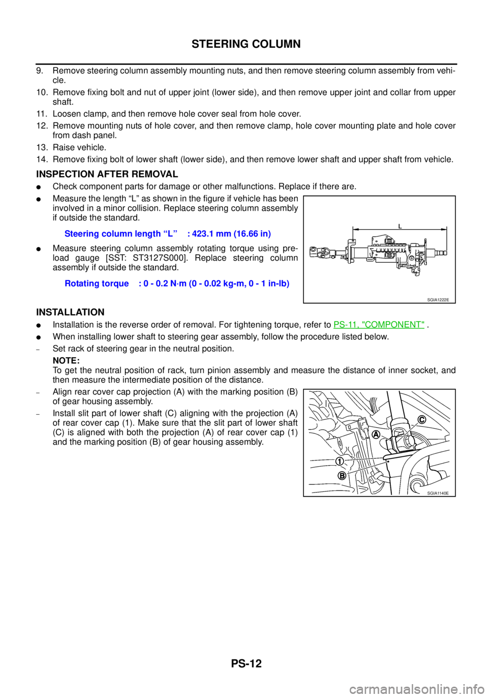
lMeasure the length “L” as shown in the figure if vehicle has been
involved in a minor collision. Replace steering column assembly
if outside the standard.
lMeasure steering column assembly rotating torque using pre-
load gauge [SST: ST3127S000]. Replace steering column
assembly if outside the standard.
INSTALLATION
lInstallation is the reverse order of removal. For tightening torque, refer toPS-11, "COMPONENT".
lWhen installing lower shaft to steering gear assembly, follow the procedure listed below.
–Set rack of steering gear in the neutral position.
NOTE:
To get the neutral position of rack, turn pinion assembly and measure the distance of inner socket, and
then measure the intermediate position of the distance.
–Align rear cover cap projection (A) with the marking position (B)
of gear housing assembly.
–Install slit part of lower shaft (C) aligning with the projection (A)
of rear cover cap (1). Make sure that the slit part of lower shaft
(C) is aligned with both the projection (A) of rear cover cap (1)
and the marking position (B) of gear housing assembly.Steering column length “L” : 423.1 mm (16.66 in)
Rotating torque : 0 - 0.2 N·m (0 - 0.02 kg-m, 0 - 1 in-lb)
SGIA1222E
SGIA1140E
Page 2651 of 3171
PS-24
POWER STEERING GEAR AND LINKAGE
22. Crimp the large-diameter boot clamp using suitable tool.
23. Install cylinder tubes to gear housing assembly.
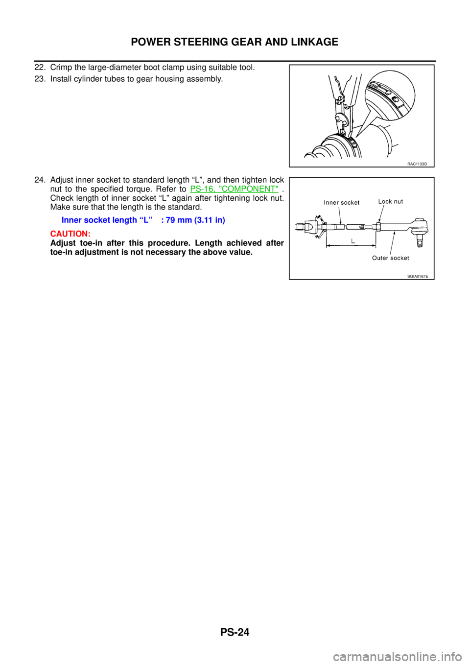
24. Adjust inner socket to standard length “L”, and then tighten lock
nut to the specified torque. Refer toPS-16, "
COMPONENT".
Check length of inner socket “L” again after tightening lock nut.
Make sure that the length is the standard.
CAUTION:
Adjust toe-in after this procedure. Length achieved after
toe-in adjustment is not necessary the above value.
RAC1133D
Inner socket length “L” : 79 mm (3.11 in)
SGIA0167E
Page 2661 of 3171
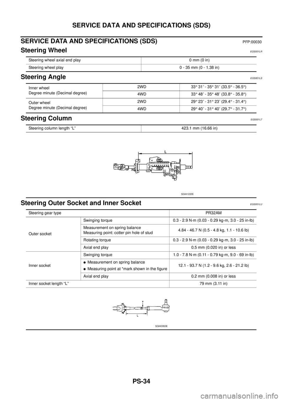
PS-34
SERVICE DATA AND SPECIFICATIONS (SDS)
SERVICE DATA AND SPECIFICATIONS (SDS)
PFP:00030
Steering WheelEGS001LR
Steering AngleEGS001LS
Steering ColumnEGS001LT
Steering Outer Socket and Inner SocketEGS001LU
Steering wheel axial end play 0 mm (0 in)
Steering wheel play 0 - 35 mm (0 - 1.38 in)
Inner wheel
Degree minute (Decimal degree)2WD 33°31¢-35°31¢(33.5°- 36.5°)
4WD 33°48¢-35°48¢(33.8°- 35.8°)
Outer wheel
Degree minute (Decimal degree)2WD 29°23¢-31°23¢(29.4°- 31.4°)
4WD 29°40¢-31°40¢(29.7°- 31.7°)
Steering column length “L” 423.1 mm (16.66 in)
SGIA1222E
Steering gear typePR32AM
Outer socketSwinging torque 0.3 - 2.9 N·m (0.03 - 0.29 kg-m, 3.0 - 25 in-lb)
Measurement on spring balance
Measuring point: cotter pin hole of stud4.84 - 46.7 N (0.5 - 4.8 kg, 1.1 - 10.6 lb)
Rotating torque 0.3 - 2.9 N·m (0.03 - 0.29 kg-m, 3.0 - 25 in-lb)
Axial end play 0.5 mm (0.020 in) or less
Inner socketSwinging torque 1.0 - 7.8 N·m (0.11 - 0.79 kg-m, 9.0 - 69 in-lb)
lMeasurement on spring balance
lMeasuring point at *mark shown in the figure12.1 - 93.7 N (1.2 - 9.6 kg, 2.6 - 21.2 lb)
Axial end play 0.2 mm (0.008 in) or less
Inner socket length “L”79 mm (3.11 in)
SGIA0950E