2005 NISSAN NAVARA length
[x] Cancel search: lengthPage 1217 of 3171
DTC P1268 - P1271 FUEL INJECTOR
EC-237
C
D
E
F
G
H
I
J
K
L
MA
EC
DTC P1268 - P1271 FUEL INJECTORPFP:16600
Component DescriptionEBS01KJ8
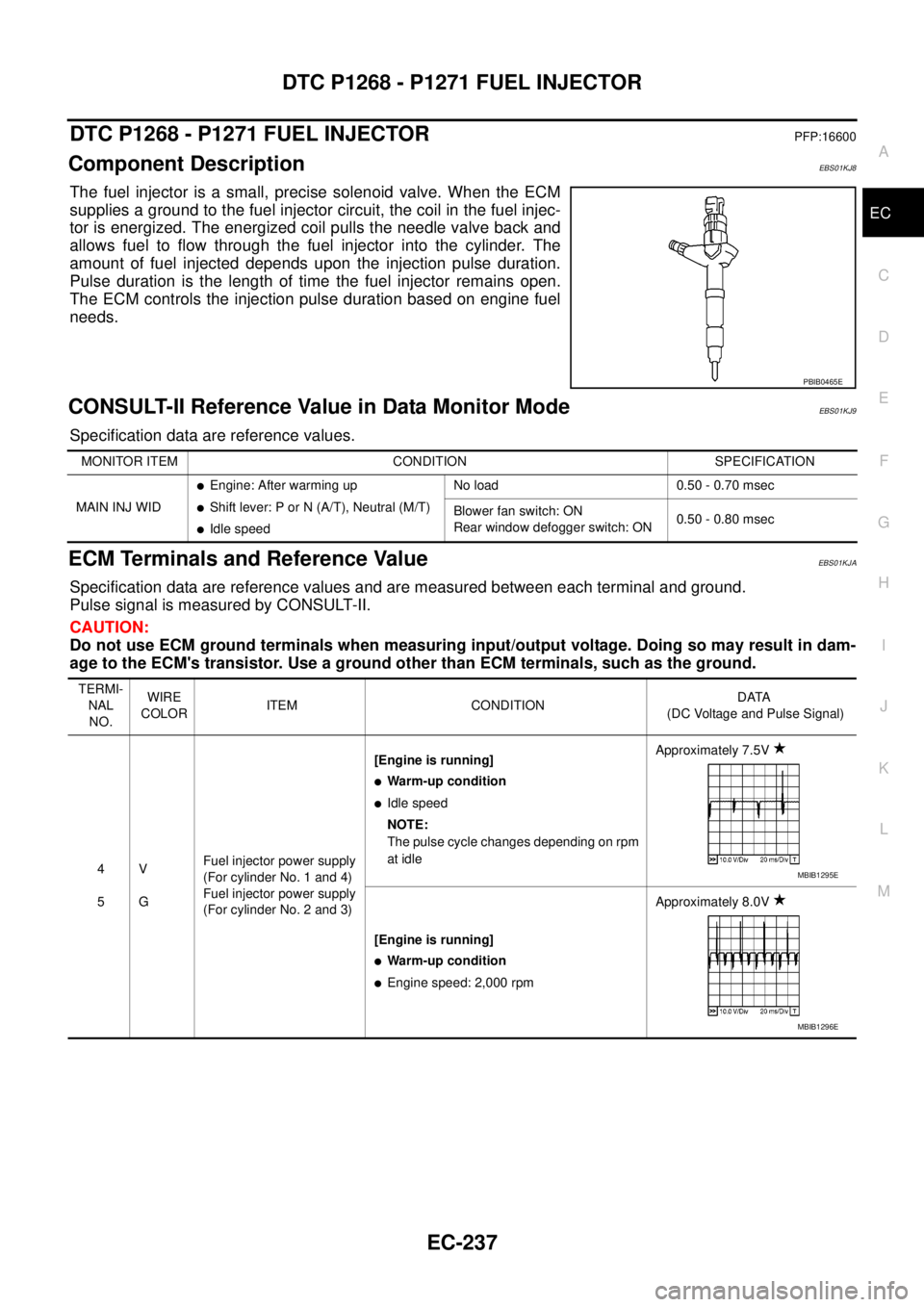
The fuel injector is a small, precise solenoid valve. When the ECM
supplies a ground to the fuel injector circuit, the coil in the fuel injec-
tor is energized. The energized coil pulls the needle valve back and
allows fuel to flow through the fuel injector into the cylinder. The
amount of fuel injected depends upon the injection pulse duration.
Pulse duration is the length of time the fuel injector remains open.
The ECM controls the injection pulse duration based on engine fuel
needs.
CONSULT-II Reference Value in Data Monitor ModeEBS01KJ9
Specification data are reference values.
ECM Terminals and Reference ValueEBS01KJA
Specification data are reference values and are measured between each terminal and ground.
Pulse signal is measured by CONSULT-II.
CAUTION:
Do not use ECM ground terminals when measuring input/output voltage. Doing so may result in dam-
age to the ECM's transistor. Use a ground other than ECM terminals, such as the ground.
PBIB0465E
MONITOR ITEM CONDITION SPECIFICATION
MAIN INJ WID
lEngine: After warming up
lShift lever: P or N (A/T), Neutral (M/T)
lIdle speedNo load 0.50 - 0.70 msec
Blower fan switch: ON
Rear window defogger switch: ON0.50 - 0.80 msec
TERMI-
NAL
NO.WIRE
COLORITEM CONDITIONDATA
(DC Voltage and Pulse Signal)
4
5V
GFuel injector power supply
(For cylinder No. 1 and 4)
Fuel injector power supply
(For cylinder No. 2 and 3)[Engine is running]
lWarm-up condition
lIdle speed
NOTE:
The pulse cycle changes depending on rpm
at idleApproximately 7.5V
[Engine is running]
lWarm-up condition
lEngine speed: 2,000 rpmApproximately 8.0V
MBIB1295E
MBIB1296E
Page 1261 of 3171
DTC P2146, P2149 FUEL INJECTOR POWER SUPPLY
EC-281
C
D
E
F
G
H
I
J
K
L
MA
EC
DTC P2146, P2149 FUEL INJECTOR POWER SUPPLYPFP:16600
Component DescriptionEBS01KL2
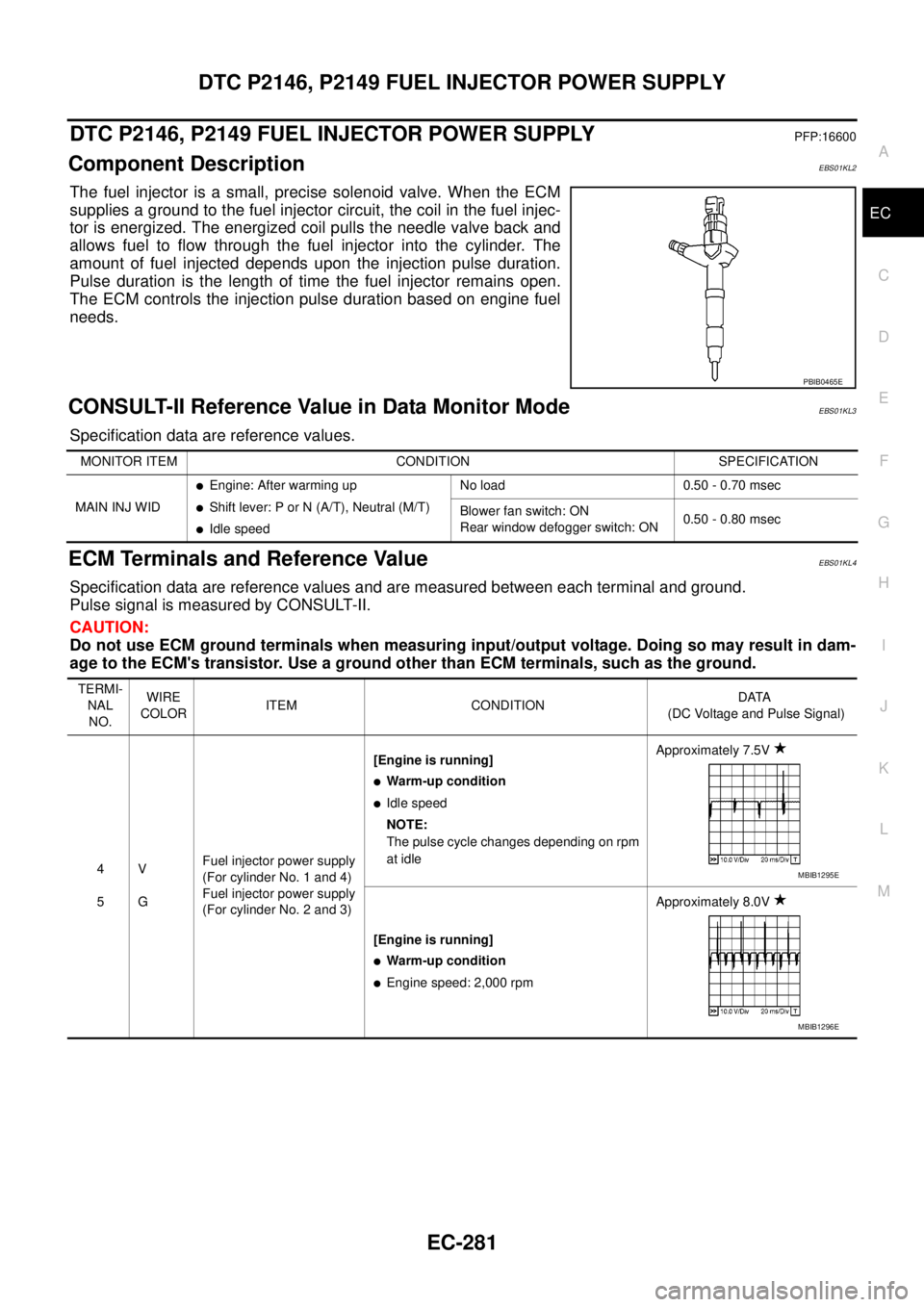
The fuel injector is a small, precise solenoid valve. When the ECM
supplies a ground to the fuel injector circuit, the coil in the fuel injec-
tor is energized. The energized coil pulls the needle valve back and
allows fuel to flow through the fuel injector into the cylinder. The
amount of fuel injected depends upon the injection pulse duration.
Pulse duration is the length of time the fuel injector remains open.
The ECM controls the injection pulse duration based on engine fuel
needs.
CONSULT-II Reference Value in Data Monitor ModeEBS01KL3
Specification data are reference values.
ECM Terminals and Reference ValueEBS01KL4
Specification data are reference values and are measured between each terminal and ground.
Pulse signal is measured by CONSULT-II.
CAUTION:
Do not use ECM ground terminals when measuring input/output voltage. Doing so may result in dam-
age to the ECM's transistor. Use a ground other than ECM terminals, such as the ground.
PBIB0465E
MONITOR ITEM CONDITION SPECIFICATION
MAIN INJ WID
lEngine: After warming up
lShift lever: P or N (A/T), Neutral (M/T)
lIdle speedNo load 0.50 - 0.70 msec
Blower fan switch: ON
Rear window defogger switch: ON0.50 - 0.80 msec
TERMI-
NAL
NO.WIRE
COLORITEM CONDITIONDATA
(DC Voltage and Pulse Signal)
4
5V
GFuel injector power supply
(For cylinder No. 1 and 4)
Fuel injector power supply
(For cylinder No. 2 and 3)[Engine is running]
lWarm-up condition
lIdle speed
NOTE:
The pulse cycle changes depending on rpm
at idleApproximately 7.5V
[Engine is running]
lWarm-up condition
lEngine speed: 2,000 rpmApproximately 8.0V
MBIB1295E
MBIB1296E
Page 1266 of 3171
EC-286
DTC P2147, P2148 FUEL INJECTOR CIRCUIT
DTC P2147, P2148 FUEL INJECTOR CIRCUIT
PFP:16600
Component DescriptionEBS01KL9
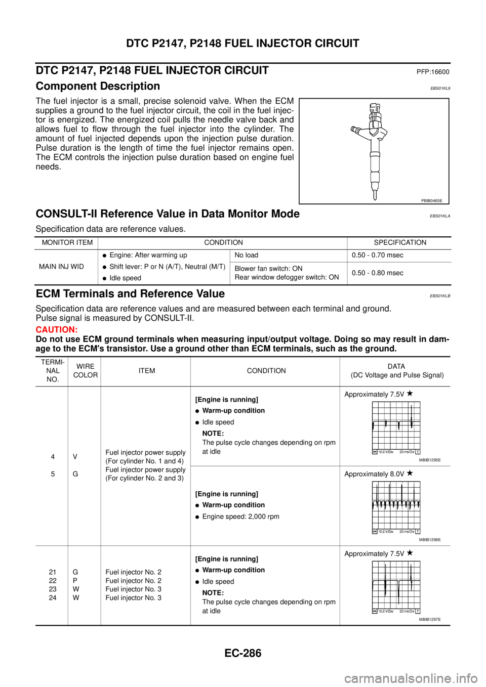
The fuel injector is a small, precise solenoid valve. When the ECM
supplies a ground to the fuel injector circuit, the coil in the fuel injec-
tor is energized. The energized coil pulls the needle valve back and
allows fuel to flow through the fuel injector into the cylinder. The
amount of fuel injected depends upon the injection pulse duration.
Pulse duration is the length of time the fuel injector remains open.
The ECM controls the injection pulse duration based on engine fuel
needs.
CONSULT-II Reference Value in Data Monitor ModeEBS01KLA
Specification data are reference values.
ECM Terminals and Reference ValueEBS01KLB
Specification data are reference values and are measured between each terminal and ground.
Pulse signal is measured by CONSULT-II.
CAUTION:
Do not use ECM ground terminals when measuring input/output voltage. Doing so may result in dam-
age to the ECM's transistor. Use a ground other than ECM terminals, such as the ground.
PBIB0465E
MONITOR ITEM CONDITION SPECIFICATION
MAIN INJ WID
lEngine: After warming up
lShift lever: P or N (A/T), Neutral (M/T)
lIdle speedNo load 0.50 - 0.70 msec
Blower fan switch: ON
Rear window defogger switch: ON0.50 - 0.80 msec
TERMI-
NAL
NO.WIRE
COLORITEM CONDITIONDATA
(DC Voltage and Pulse Signal)
4
5V
GFuel injector power supply
(For cylinder No. 1 and 4)
Fuel injector power supply
(For cylinder No. 2 and 3)[Engine is running]
lWarm-up condition
lIdle speed
NOTE:
The pulse cycle changes depending on rpm
at idleApproximately 7.5V
[Engine is running]
lWarm-up condition
lEngine speed: 2,000 rpmApproximately 8.0V
21
22
23
24G
P
W
WFuel injector No. 2
Fuel injector No. 2
Fuel injector No. 3
Fuel injector No. 3[Engine is running]
lWarm-up condition
lIdle speed
NOTE:
The pulse cycle changes depending on rpm
at idleApproximately 7.5V
MBIB1295E
MBIB1296E
MBIB1297E
Page 1421 of 3171
OIL PAN AND OIL STRAINER
EM-39
C
D
E
F
G
H
I
J
K
L
MA
EM
CAUTION:
Install avoiding misalignment of O-ring.
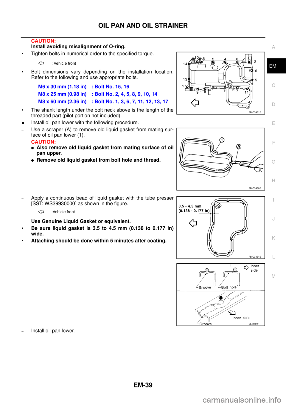
• Tighten bolts in numerical order to the specified torque.
• Bolt dimensions vary depending on the installation location.
Refer to the following and use appropriate bolts.
• The shank length under the bolt neck above is the length of the
threaded part (pilot portion not included).
lInstall oil pan lower with the following procedure.
–Use a scraper (A) to remove old liquid gasket from mating sur-
face of oil pan lower (1).
CAUTION:
lAlso remove old liquid gasket from mating surface of oil
pan upper.
lRemove old liquid gasket from bolt hole and thread.
–Apply a continuous bead of liquid gasket with the tube presser
[SST: WS39930000] as shown in the figure.
Use Genuine Liquid Gasket or equivalent.
•Be sure liquid gasket is 3.5 to 4.5 mm (0.138 to 0.177 in)
wide.
•Attaching should be done within 5 minutes after coating.
–Install oil pan lower.
: Vehicle front
M6x30mm(1.18in) :BoltNo.15,16
M8 x 25 mm (0.98 in) : Bolt No. 2, 4, 5, 8, 9, 10, 14
M8 x 60 mm (2.36 in) : Bolt No. 1, 3, 6, 7, 11, 12, 13, 17
PBIC3431E
PBIC3430E
:Vehicle front
PBIC3434E
SEM159F
Page 1433 of 3171
![NISSAN NAVARA 2005 Repair Workshop Manual FUEL PUMP
EM-51
C
D
E
F
G
H
I
J
K
L
MA
EM
8. Using the sprocket holder [SST], hold fuel pump sprocket to pre-
vent falling.
lFor sprocket holder, use KV11106060 machined as shown in
the figure, becaus NISSAN NAVARA 2005 Repair Workshop Manual FUEL PUMP
EM-51
C
D
E
F
G
H
I
J
K
L
MA
EM
8. Using the sprocket holder [SST], hold fuel pump sprocket to pre-
vent falling.
lFor sprocket holder, use KV11106060 machined as shown in
the figure, becaus](/manual-img/5/57362/w960_57362-1432.png)
FUEL PUMP
EM-51
C
D
E
F
G
H
I
J
K
L
MA
EM
8. Using the sprocket holder [SST], hold fuel pump sprocket to pre-
vent falling.
lFor sprocket holder, use KV11106060 machined as shown in
the figure, because the previous bore is not fitting.
lWhen the sprocket holder is installed, if the positioning stop-
per pin [SST] interferes, pull out the positioning stopper pin
approximately 10 mm (0.39 in), then install it.
lAfter the sprocket holder is installed temporarily, tighten the
sprocket holder after making extension bar and TORX socket
(size: E10) (commercial service tool) insert into the machined
bore.
lThe length of the sprocket holder mounting bolts should be
approximately 15 mm (0.59 in) (M6 thread length).
lMake sure that the a- and b-faces of the sprocket holder con-
tact the bottom side of the sprocket (small diameter side).
CAUTION:
Do not remove the sprocket holder [SST] until fuel pump is installed.
lAfter the sprocket holder is installed, pull out the positioning
stopper pin from fuel pump sprocket.
9. Using the extension bar and the TORX socket (size: E10) (com-
mercial service tool), remove the tightening bolts.
CAUTION:
Do not disassemble or adjust fuel pump.
10. Remove the fuel pump toward the rear of engine.
CAUTION:
For removal, be careful not to drop the seal washer into the engine.
NOTE:
The seal washer of the tightening bolts cannot be reused.
11. Remove adjusting shim.
12. Attach a suitable tool in the M8 bolt hole on coupling.
SBIA0217E
PBIC2534E
MBIA0075E
PBIC2405E
Page 1463 of 3171
![NISSAN NAVARA 2005 Repair Workshop Manual PRIMARY TIMING CHAIN
EM-81
C
D
E
F
G
H
I
J
K
L
MA
EM
c. Using the pulley puller [SST], remove crankshaft pulley.
lUse two M6 bolts with approx. 60 mm (2.36 in) shank length
for securing crankshaft pul NISSAN NAVARA 2005 Repair Workshop Manual PRIMARY TIMING CHAIN
EM-81
C
D
E
F
G
H
I
J
K
L
MA
EM
c. Using the pulley puller [SST], remove crankshaft pulley.
lUse two M6 bolts with approx. 60 mm (2.36 in) shank length
for securing crankshaft pul](/manual-img/5/57362/w960_57362-1462.png)
PRIMARY TIMING CHAIN
EM-81
C
D
E
F
G
H
I
J
K
L
MA
EM
c. Using the pulley puller [SST], remove crankshaft pulley.
lUse two M6 bolts with approx. 60 mm (2.36 in) shank length
for securing crankshaft pulley.
9. Remove oil pump housing.
lLoosen bolts in reverse order of that shown in the figure and
remove them.
lU s e t h e s e a l c u t t e r [ S S T: K V 1 0 1111 0 0 ] e t c . f o r r e m o v a l .
10. Remove crankshaft gear.
lRemove crankshaft gear (1) with the following procedure
(4WD models).
a. Make sure that No.1 piston is TDC on its compression stroke.
b. Turn the idler sub gear (3) counterclockwise with snap ring plier
(B) or suitable tool for aligning idler sub gear (3) and idler main
gear (2).
lIf idler gear rotates, hold the flat faces on balancer drive shaft
front end (4).
c. Install internal mechanism securing bolt and plate (Service part:
13012 EB30A and 13013 EB30A) (A) and tighten to the speci-
fied torque.
CAUTION:
lDo not loosen idler gear mounting bolt (5).
lOnly use the genuine internal mechanism securing bolt
and plate (A), or the idler gear (2) and (3) will be damaged.
lDo not remove internal mechanism securing bolt and
plate (A) from idler gear (2) and (3) until crankshaft gear
(1) and all of the parts in connection have been installed.
lIf internal mechanism securing bolt and plate (A) is not
installed, internal mechanism of idler gear (2) and (3) will
disengage after crankshaft gear (1) is removed. This will prohibit the balancer unit from being
reusable.
d. Apply mating marks (C) to crankshaft gear (1) and idler sub gear (3).
e. Remove crankshaft gear (1).
11. Remove front oil seal from oil pump housing.
lPunch out the seal off from the back surface of the oil pump housing using a flat-bladed screwdriver.
CAUTION:
Be careful not to damage oil pump housing.
JEM132G
PBIC3470E
: 4.0 N·m (0.41 kg-m, 35 in-lb)
PBIC3471E
Page 1469 of 3171
PRIMARY TIMING CHAIN
EM-87
C
D
E
F
G
H
I
J
K
L
MA
EM
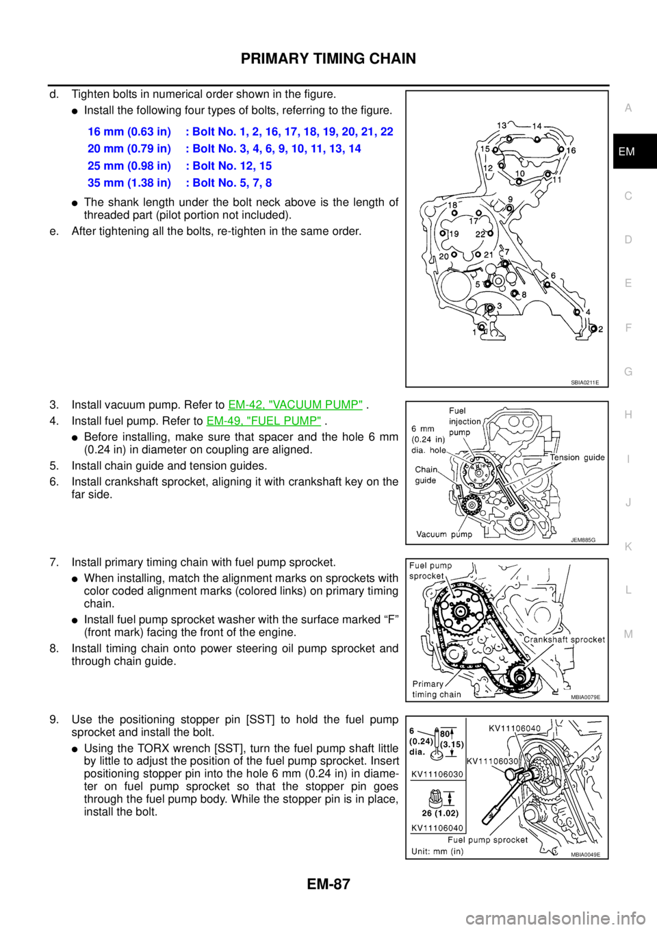
d. Tighten bolts in numerical order shown in the figure.
lInstall the following four types of bolts, referring to the figure.
lThe shank length under the bolt neck above is the length of
threaded part (pilot portion not included).
e. After tightening all the bolts, re-tighten in the same order.
3. Install vacuum pump. Refer toEM-42, "
VACUUM PUMP".
4. Install fuel pump. Refer toEM-49, "
FUEL PUMP".
lBefore installing, make sure that spacer and the hole 6 mm
(0.24 in) in diameter on coupling are aligned.
5. Install chain guide and tension guides.
6. Install crankshaft sprocket, aligning it with crankshaft key on the
far side.
7. Install primary timing chain with fuel pump sprocket.
lWhen installing, match the alignment marks on sprockets with
color coded alignment marks (colored links) on primary timing
chain.
lInstall fuel pump sprocket washer with the surface marked “F”
(front mark) facing the front of the engine.
8. Install timing chain onto power steering oil pump sprocket and
through chain guide.
9. Use the positioning stopper pin [SST] to hold the fuel pump
sprocket and install the bolt.
lUsing the TORX wrench [SST], turn the fuel pump shaft little
by little to adjust the position of the fuel pump sprocket. Insert
positioning stopper pin into the hole 6 mm (0.24 in) in diame-
ter on fuel pump sprocket so that the stopper pin goes
through the fuel pump body. While the stopper pin is in place,
install the bolt.16 mm (0.63 in) : Bolt No. 1, 2, 16, 17, 18, 19, 20, 21, 22
20mm(0.79in) :BoltNo.3,4,6,9,10,11,13,14
25 mm (0.98 in) : Bolt No. 12, 15
35 mm (1.38 in) : Bolt No. 5, 7, 8
SBIA0211E
JEM885G
MBIA0079E
MBIA0049E
Page 1518 of 3171

EM-136
SERVICE DATA AND SPECIFICATIONS (SDS)
CYLINDER HEAD
Unit: mm (in)
VA LV E
Valve Dimensions
Unit: mm (in)
Valve Clearance
Unit: mm (in)
*: Approximately 80°C (176°F) Item Standard Limit
Cylinder head distortion Less than 0.04 (0.0016) 0.1 (0.004)
JEM204G
Valve head diameter “D”Intake 28.0 - 28.3 (1.102 - 1.114)
Exhaust 26.0 - 26.3 (1.024 - 1.035)
Valve length “L”Intake 106.72 (4.2016)
Exhaust 106.36 (4.1874)
Valve stem diameter “d”Intake 5.965 - 5.980 (0.2348 - 0.2354)
Exhaust 5.945 - 5.960 (0.2341 - 0.2346)
Valve seat angle “a” Intake and exhaust 45 degrees 15¢- 45 degrees 45¢
Valvemargin“T”Intake 1.60 (0.0630)
Exhaust2WD models 1.80 (0.0709)
4WD models 1.48 (0.0583)
Valvemargin“T”limitMore than 1.0 (0.039)
Valve stem end surface grinding limit Less than 0.2 (0.008)
SEM188
Item Cold Hot* (Reference data)
Intake 0.24 - 0.32 (0.0094 - 0.0126) 0.274 - 0.386 (0.0108 - 0.0152)
Exhaust 0.26 - 0.34 (0.0102 - 0.0134) 0.308 - 0.432 (0.0121 - 0.0170)