2005 NISSAN NAVARA engine overheat
[x] Cancel search: engine overheatPage 1025 of 3171
TROUBLE DIAGNOSIS
EC-45
C
D
E
F
G
H
I
J
K
L
MA
EC
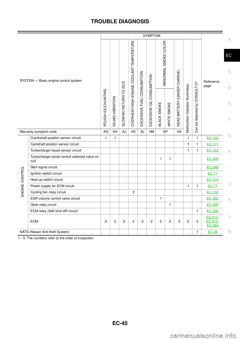
1 - 5: The numbers refer to the order of inspection.
ENGINE CONTROL
Crankshaft position sensor circuit 1 1 1 1EC-159
Camshaft position sensor circuit11EC-171
Turbocharger boost sensor circuit 1 1EC-153
Turbocharger boost control solenoid valve cir-
cuit11EC-309
Start signal circuitEC-348
Ignition switch circuitEC-71
Heat up switch circuitEC-319
Power supply for ECM circuit11EC-71
Cooling fan relay circuit 2EC-132
EGR volume control valve circuit 1EC-302
Glow relay circuit1EC-295
ECM relay (Self shut-off) circuit1EC-232
ECM 22 22222 2222EC-213
,
EC-215
,
EC-269
NATS (Nissan Anti-theft System)1EC-28
SYSTEM — Basic engine control systemSYMPTOM
Reference
page
ROUGH IDLE/HUNTING
IDLING VIBRATION
SLOW/NO RETURN TO IDLE
OVERHEAT/HIGH ENGINE COOLANT TEMPERATURE
EXCESSIVE FUEL CONSUMPTION
EXCESSIVE OIL CONSUMPTION
ABNORMAL SMOKE COLOR
DEAD BATTERY (UNDER CHARGE)
Malfunction indicator illuminates.
Can be detected by CONSULT-II?BLACK SMOKE
WHITE SMOKE
Warranty symptom code AG AH AJ AK AL AM AP HA
Page 1045 of 3171
TROUBLE DIAGNOSIS
EC-65
C
D
E
F
G
H
I
J
K
L
MA
EC
*: Leaving cooling fan OFF with CONSULT-II while engine is running may cause the engine to overheat.
REAL TIME DIAGNOSIS IN DATA MONITOR MODE
CONSULT-II has two kinds of triggers and they can be selected by touching “SETTING” in “DATA MONITOR”
mode.
1. “AUTO TRIG” (Automatic trigger):
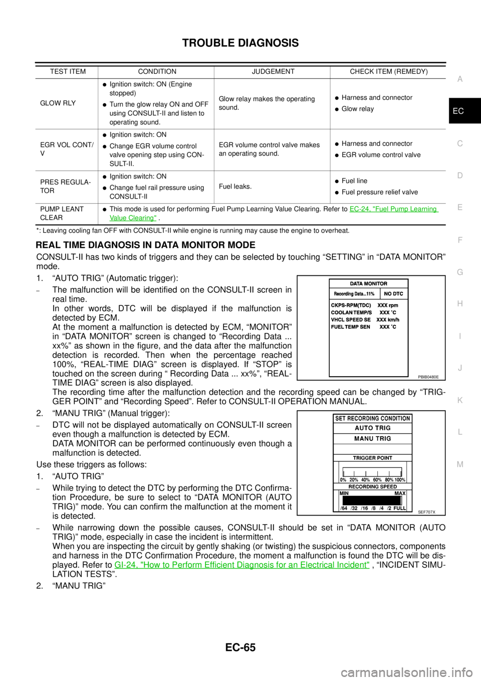
–The malfunction will be identified on the CONSULT-II screen in
real time.
In other words, DTC will be displayed if the malfunction is
detected by ECM.
At the moment a malfunction is detected by ECM, “MONITOR”
in “DATA MONITOR” screen is changed to “Recording Data ...
xx%” as shown in the figure, and the data after the malfunction
detection is recorded. Then when the percentage reached
100%, “REAL-TIME DIAG” screen is displayed. If “STOP” is
touched on the screen during “ Recording Data ... xx%”, “REAL-
TIME DIAG” screen is also displayed.
The recording time after the malfunction detection and the recording speed can be changed by “TRIG-
GER POINT” and “Recording Speed”. Refer to CONSULT-II OPERATION MANUAL.
2. “MANU TRIG” (Manual trigger):
–DTC will not be displayed automatically on CONSULT-II screen
even though a malfunction is detected by ECM.
DATA MONITOR can be performed continuously even though a
malfunction is detected.
Use these triggers as follows:
1. “AUTO TRIG”
–While trying to detect the DTC by performing the DTC Confirma-
tion Procedure, be sure to select to “DATA MONITOR (AUTO
TRIG)” mode. You can confirm the malfunction at the moment it
is detected.
–While narrowing down the possible causes, CONSULT-II should be set in “DATA MONITOR (AUTO
TRIG)” mode, especially in case the incident is intermittent.
When you are inspecting the circuit by gently shaking (or twisting) the suspicious connectors, components
and harness in the DTC Confirmation Procedure, the moment a malfunction is found the DTC will be dis-
played. Refer toGI-24, "
How to Perform Efficient Diagnosis for an Electrical Incident", “INCIDENT SIMU-
LATION TESTS”.
2. “MANU TRIG”
GLOW RLY
lIgnition switch: ON (Engine
stopped)
lTurn the glow relay ON and OFF
using CONSULT-II and listen to
operating sound.Glow relay makes the operating
sound.lHarness and connector
lGlow relay
EGR VOL CONT/
V
lIgnition switch: ON
lChange EGR volume control
valve opening step using CON-
SULT-II.EGR volume control valve makes
an operating sound.lHarness and connector
lEGR volume control valve
PRES REGULA-
TOR
lIgnition switch: ON
lChange fuel rail pressure using
CONSULT-IIFuel leaks.lFuel line
lFuel pressure relief valve
PUMP LEANT
CLEAR
lThis mode is used for performing Fuel Pump Learning Value Clearing. Refer toEC-24, "Fuel Pump Learning
Value Clearing". TEST ITEM CONDITION JUDGEMENT CHECK ITEM (REMEDY)
PBIB0480E
SEF707X
Page 1113 of 3171
DTC P0217 ENGINE OVER TEMPERATURE
EC-133
C
D
E
F
G
H
I
J
K
L
MA
EC
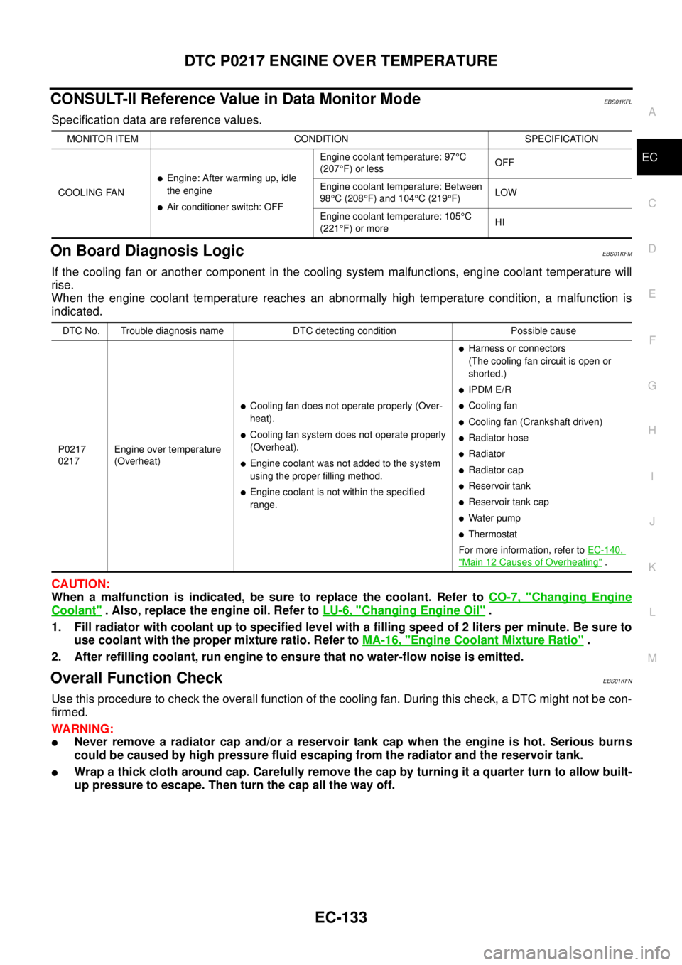
CONSULT-II Reference Value in Data Monitor ModeEBS01KFL
Specification data are reference values.
On Board Diagnosis LogicEBS01KFM
If the cooling fan or another component in the cooling system malfunctions, engine coolant temperature will
rise.
When the engine coolant temperature reaches an abnormally high temperature condition, a malfunction is
indicated.
CAUTION:
When a malfunction is indicated, be sure to replace the coolant. Refer toCO-7, "
Changing Engine
Coolant". Also, replace the engine oil. Refer toLU-6, "Changing Engine Oil".
1. Fill radiator with coolant up to specified level with a filling speed of 2 liters per minute. Be sure to
use coolant with the proper mixture ratio. Refer toMA-16, "
Engine Coolant Mixture Ratio".
2. After refilling coolant, run engine to ensure that no water-flow noise is emitted.
Overall Function CheckEBS01KFN
Use this procedure to check the overall function of the cooling fan. During this check, a DTC might not be con-
firmed.
WARNING:
lNever remove a radiator cap and/or a reservoir tank cap when the engine is hot. Serious burns
could be caused by high pressure fluid escaping from the radiator and the reservoir tank.
lWrap a thick cloth around cap. Carefully remove the cap by turning it a quarter turn to allow built-
up pressure to escape. Then turn the cap all the way off.
MONITOR ITEM CONDITION SPECIFICATION
COOLING FAN
lEngine: After warming up, idle
the engine
lAir conditioner switch: OFFEngine coolant temperature: 97°C
(207°F) or lessOFF
Engine coolant temperature: Between
98°C (208°F) and 104°C(219°F)LOW
Engine coolant temperature: 105°C
(221°F) or moreHI
DTC No. Trouble diagnosis name DTC detecting condition Possible cause
P0217
0217Engine over temperature
(Overheat)
lCooling fan does not operate properly (Over-
heat).
lCooling fan system does not operate properly
(Overheat).
lEngine coolant was not added to the system
using the proper filling method.
lEngine coolant is not within the specified
range.
lHarness or connectors
(The cooling fan circuit is open or
shorted.)
lIPDM E/R
lCooling fan
lCooling fan (Crankshaft driven)
lRadiator hose
lRadiator
lRadiator cap
lReservoir tank
lReservoir tank cap
lWater pump
lThermostat
For more information, refer toEC-140,
"Main 12 Causes of Overheating".
Page 1118 of 3171
EC-138
DTC P0217 ENGINE OVER TEMPERATURE
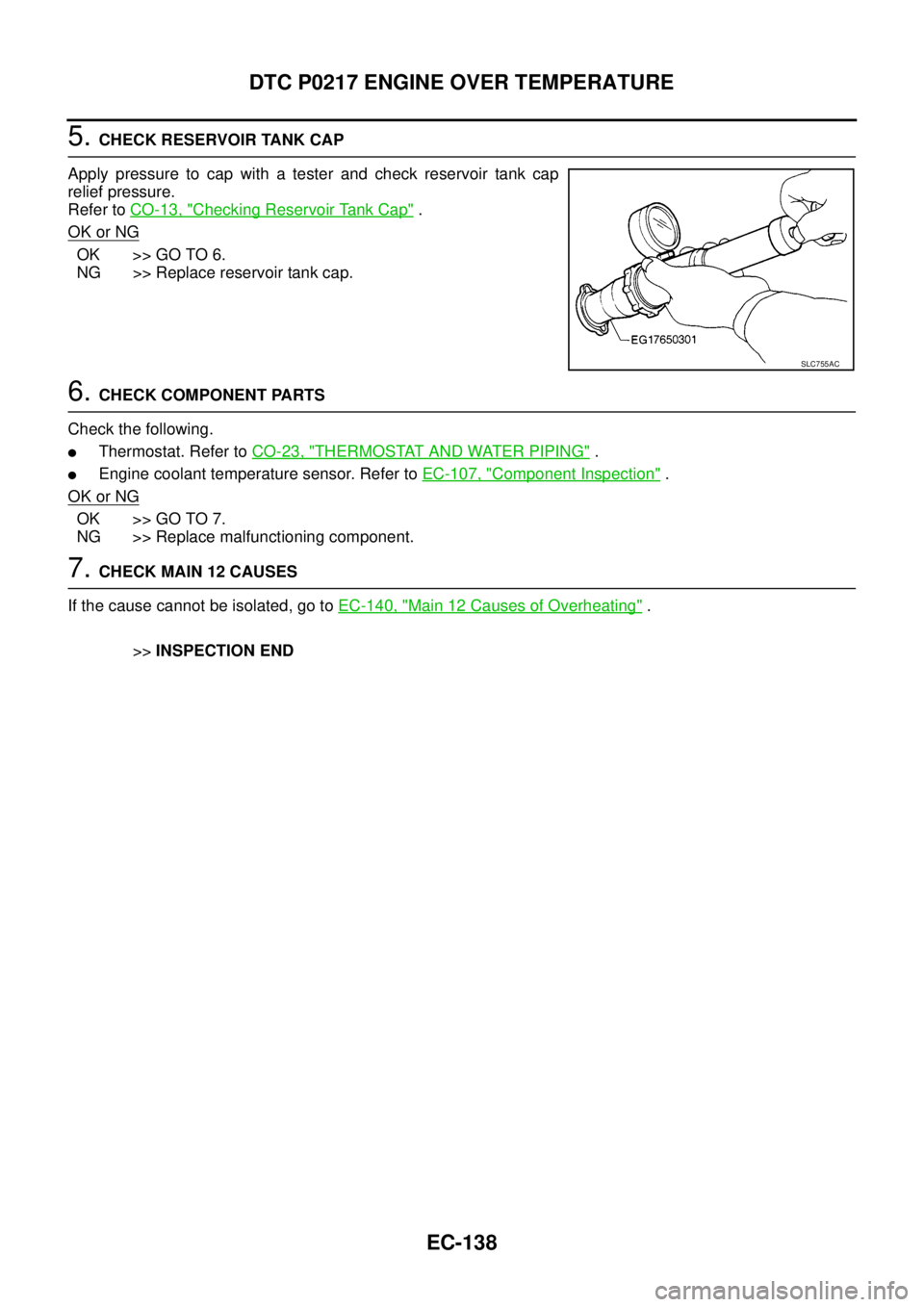
5.CHECK RESERVOIR TANK CAP
Apply pressure to cap with a tester and check reservoir tank cap
relief pressure.
Refer toCO-13, "
Checking Reservoir Tank Cap".
OK or NG
OK >> GO TO 6.
NG >> Replace reservoir tank cap.
6.CHECK COMPONENT PARTS
Check the following.
lThermostat. Refer toCO-23, "THERMOSTAT AND WATER PIPING".
lEngine coolant temperature sensor. Refer toEC-107, "Component Inspection".
OK or NG
OK >> GO TO 7.
NG >> Replace malfunctioning component.
7.CHECK MAIN 12 CAUSES
If the cause cannot be isolated, go toEC-140, "
Main 12 Causes of Overheating".
>>INSPECTION END
SLC755AC
Page 1120 of 3171
EC-140
DTC P0217 ENGINE OVER TEMPERATURE
5.CHECK COOLING FAN MOTOR
Refer toEC-141, "
Component Inspection".
OK or NG
OK >> GO TO 6.
NG >> Replace cooling fan motors.
6.CHECK INTERMITTENT INCIDENT
PerformEC-70, "
TROUBLE DIAGNOSIS FOR INTERMITTENT INCIDENT".
OK or NG
OK >> Replace IPDM E/R. Refer toPG-14, "IPDM E/R (INTELLIGENT POWER DISTRIBUTION MOD-
ULE ENGINE ROOM)".
NG >> Repair or replace harness or connector.
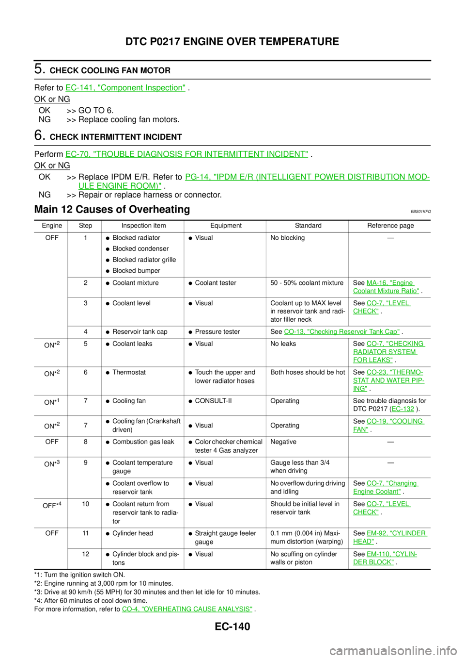
Main 12 Causes of OverheatingEBS01KFQ
*1: Turn the ignition switch ON.
*2: Engine running at 3,000 rpm for 10 minutes.
*3: Drive at 90 km/h (55 MPH) for 30 minutes and then let idle for 10 minutes.
*4: After 60 minutes of cool down time.
For more information, refer toCO-4, "
OVERHEATING CAUSE ANALYSIS". Engine Step Inspection item Equipment Standard Reference page
OFF 1
lBlocked radiator
lBlocked condenser
lBlocked radiator grille
lBlocked bumper
lVisual No blocking —
2
lCoolant mixturelCoolant tester 50 - 50% coolant mixture SeeMA-16, "Engine
Coolant Mixture Ratio".
3
lCoolant levellVisual Coolant up to MAX level
in reservoir tank and radi-
ator filler neckSeeCO-7, "LEVEL
CHECK".
4
lReservoir tank caplPressure tester SeeCO-13, "Checking Reservoir Tank Cap".
ON*
25lCoolant leakslVisual No leaks SeeCO-7, "CHECKING
RADIATOR SYSTEM
FOR LEAKS".
ON*
26lThermostatlTouch the upper and
lower radiator hosesBoth hoses should be hot SeeCO-23, "THERMO-
STAT AND WATER PIP-
ING".
ON*
17lCooling fanlCONSULT-II Operating See trouble diagnosis for
DTC P0217 (EC-132
).
ON*
27lCooling fan (Crankshaft
driven)lVisual OperatingSeeCO-19, "COOLING
FA N".
OFF 8
lCombustion gas leaklColor checker chemical
tester 4 Gas analyzerNegative —
ON*
39lCoolant temperature
gaugelVisual Gauge less than 3/4
when driving—
lCoolant overflow to
reservoir tanklVisual No overflow during driving
and idlingSeeCO-7, "Changing
Engine Coolant".
OFF*
410lCoolant return from
reservoir tank to radia-
torlVisual Should be initial level in
reservoir tankSeeCO-7, "LEVEL
CHECK".
OFF 11
lCylinder headlStraight gauge feeler
gauge0.1 mm (0.004 in) Maxi-
mum distortion (warping)SeeEM-92, "CYLINDER
HEAD".
12
lCylinder block and pis-
tonslVisual No scuffing on cylinder
walls or pistonSeeEM-110, "CYLIN-
DER BLOCK".
Page 1757 of 3171
IDX-5
A
C
D
E
F
G
H
I
J
K
L B
IDX
ALPHABETICAL INDEX
HSEAT - Wiring diagram .......................SE-14,SE-17
I
IATS - Wiring diagram .....................................EC-100
Identification plate ...............................................GI-57
Idle speed ..........................................................EC-38
Ignition key hole illumination .............................LT-145
ILL - Wiring diagram .........................................LT-166
Illumination .......................................................LT-162
In vehicle sensor ...........................ATC-108,ATC-118
INJE/PW - Wiring diagram ...............................EC-284
INJECT - Wiring diagram .....EC-128,EC-240,EC-289
Injection nozzle .......EM-44,EC-123,EC-125,EC-237
Injector adjustment value ...................EC-271,EC-273
Injector adjustment value registration ................EC-25
Input clutch solenoid valve .................AT-132,AT-134
Instrument panel ..................................................IP-10
INT/V - Wiring diagram ....................................EC-315
Intake air control valve control solenoid valve .EC-314
Intake air temperature sensor ............................EC-98
Intake door control linkage adjustment ............ATC-79
Intake door motor ..........ATC-77,ATC-129,MTC-109
Intake manifold ..................................................EM-20
Intake sensor ..ATC-114,ATC-120,MTC-95,MTC-99
Interior .................................................................EI-33
Interior lamp ......................................................LT-145
Interior lamp on-off control ................................LT-145
IPDM (Intelligent power distribution module engine
room) .................................................................PG-14
ISO 15031-2 Terminology ..................................GI-61
J
Jacking points .....................................................GI-52
K
Key illumination ................................................LT-145
KEYLES - Wiring diagram ..................................BL-93
L
Leaf spring (rear) ..............................................RSU-7
Length (Dimensions) ..........................................GI-60
License lamp ....................................................LT-125
Lifting points .......................................................GI-52
Line pressure solenoid valve ...........................AT-114
Line pressure test (A/T) .....................................AT-44
Liquid gasket application ................EM-5,LU-2,CO-2
Location of electrical units .................................PG-71
Low coast brake solenoid valve ..........AT-152,AT-154
Lubricant (R134a) A/C ......................ATC-24,MTC-24
Lubricants ..........................................................MA-14
Lubrication circuit (engine) ..................................LU-4
Lubrication oil A/C ............................ATC-24,MTC-24
Lubrication-locks, hinges and hood latches .......MA-39
M
MAFS - Wiring diagram .....................................EC-94
Magnet clutch .ATC-87,ATC-143,MTC-79,MTC-123
MAIN - Wiring diagram ......................................EC-72
Main drive gear (M/T) ........................................MT-21
Mainshaft (M/T) ..................................................MT-21
Major overhaul (Final drive)FFD-17,RFD-15,RFD-82
Major overhaul (Transfer) ................................TF-112
Malfunction indicator (MI) ..................................EC-28
Map lamp ..........................................................LT-145
Mass air flow sensor (MAFS) .............................EC-92
Master cylinder (brake) ......................................BR-17
Master cylinder (clutch) ........................................CL-9
Meter .....................................................................DI-4
METER - Wiring diagram ....................................DI-10
MI & data link connectors circuit ......................EC-354
MIL/DL - Wiring diagram ..................................EC-354
Mode door control linkage adjustment ............ATC-65,
MTC-59
Mode door motor ............ATC-63,ATC-130,MTC-58,
MTC-110
Model variation ...................................................GI-56
Multiport fuel injection precautions .......................GI-6
N
NATS - Wiring diagram ....................................BL-173
NATS (Nissan anti-theft system) precautions .......GI-3
NVH troubleshooting (AX) .................................FAX-4
NVH troubleshooting (BR) ...................................BR-5
NVH troubleshooting (EM) ................................EM-10
NVH troubleshooting (Final drive) ........FFD-6,RFD-7,
RFD-39
NVH troubleshooting (M/T) ..................................MT-6
NVH troubleshooting (Propeller shaft) .................PR-2
NVH troubleshooting (ST) ....................................PS-5
NVH troubleshooting (Transfer) .........................TF-11
NVH troubleshooting (WT)NVH troubleshooting (WT) .
WT-2
O
Oil cooler (engine) .............................................LU-11
Oil filter .................................................................LU-8
Oil pan (engine) ................................................EM-36
Oil pressure (engine) ...........................................LU-5
Oil pump (A/T) .................................................AT-281
Oil pump (engine) ..............................................LU-14
Oil seal replacement (engine) ...........................EM-70
Oil seal replacement (front of final drive) ...........FFD-9
Oil seal replacement (side of final drive) ..........FFD-13
On board diagnostic system ..............................EC-27
Operating cylinder (clutch) .................................CL-11
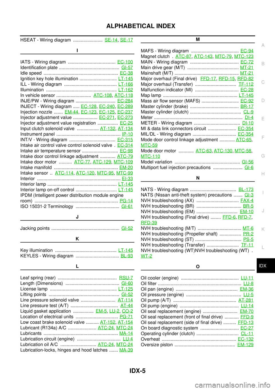
Overheat ..........................................................EC-132
Oversize piston ...............................................EM-129
Page 2295 of 3171
MA-20
ENGINE MAINTENANCE
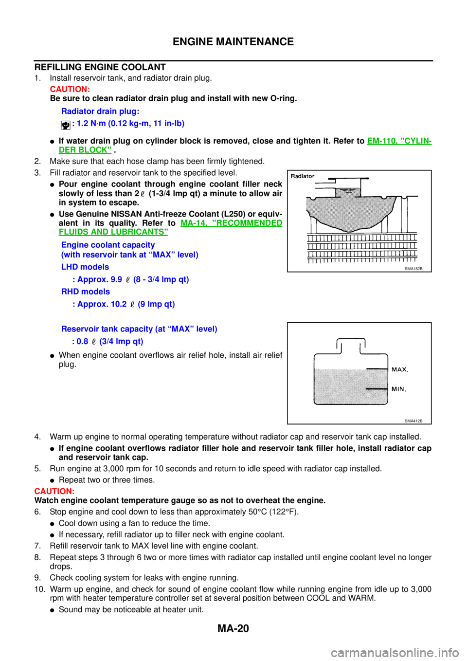
REFILLING ENGINE COOLANT
1. Install reservoir tank, and radiator drain plug.
CAUTION:
Be sure to clean radiator drain plug and install with new O-ring.
lIf water drain plug on cylinder block is removed, close and tighten it. Refer toEM-110, "CYLIN-
DER BLOCK".
2. Make sure that each hose clamp has been firmly tightened.
3. Fill radiator and reservoir tank to the specified level.
lPour engine coolant through engine coolant filler neck
slowly of less than 2 (1-3/4 lmp qt) a minute to allow air
in system to escape.
lUse Genuine NISSAN Anti-freeze Coolant (L250) or equiv-
alent in its quality. Refer toMA-14, "
RECOMMENDED
FLUIDS AND LUBRICANTS"
lWhen engine coolant overflows air relief hole, install air relief
plug.
4. Warm up engine to normal operating temperature without radiator cap and reservoir tank cap installed.
lIf engine coolant overflows radiator filler hole and reservoir tank filler hole, install radiator cap
and reservoir tank cap.
5. Run engine at 3,000 rpm for 10 seconds and return to idle speed with radiator cap installed.
lRepeat two or three times.
CAUTION:
Watch engine coolant temperature gauge so as not to overheat the engine.
6. Stop engine and cool down to less than approximately 50°C(122°F).
lCool down using a fan to reduce the time.
lIf necessary, refill radiator up to filler neck with engine coolant.
7. Refill reservoir tank to MAX level line with engine coolant.
8. Repeat steps 3 through 6 two or more times with radiator cap installed until engine coolant level no longer
drops.
9. Check cooling system for leaks with engine running.
10. Warm up engine, and check for sound of engine coolant flow while running engine from idle up to 3,000
rpm with heater temperature controller set at several position between COOL and WARM.
lSound may be noticeable at heater unit.Radiator drain plug:
: 1.2 N·m (0.12 kg-m, 11 in-lb)
Engine coolant capacity
(with reservoir tank at “MAX” level)
LHD models
: Approx. 9.9 (8 - 3/4 lmp qt)
RHD models
: Approx. 10.2 (9 lmp qt)
SMA182B
Reservoir tank capacity (at “MAX” level)
: 0.8 (3/4 lmp qt)
SMA412B
Page 2477 of 3171
MTC-90
TROUBLE DIAGNOSIS
TROUBLE DIAGNOSES FOR UNUSUAL PRESSURE
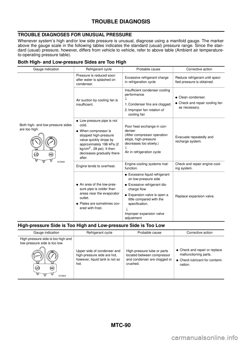
Whenever system¢s high and/or low side pressure is unusual, diagnose using a manifold gauge. The marker
above the gauge scale in the following tables indicates the standard (usual) pressure range. Since the stan-
dard (usual) pressure, however, differs from vehicle to vehicle, refer to above table (Ambient air temperature-
to-operating pressure table).
Both High- and Low-pressure Sides are Too High
High-pressure Side is Too High and Low-pressure Side is Too Low
Gauge indication Refrigerant cycle Probable cause Corrective action
Both high- and low-pressure sides
are too high.Pressure is reduced soon
after water is splashed on
condenser.Excessive refrigerant charge
in refrigeration cycleReduce refrigerant until speci-
fied pressure is obtained.
Air suction by cooling fan is
insufficient.Insufficient condenser cooling
performance
¯
1. Condenser fins are clogged.
2. Improper fan rotation of
cooling fan
lClean condenser.
lCheck and repair cooling fan
as necessary.
lLow-pressure pipe is not
cold.
lWhen compressor is
stopped high-pressure
value quickly drops by
approximately 196 kPa (2
kg/cm
2,28psi).Itthen
decreases gradually there-
after.Poor heat exchange in con-
denser
(After compressor operation
stops, high-pressure
decreases too slowly.)
¯
Air in refrigeration cycleEvacuate repeatedly and
recharge system.
Engine tends to overheat.Engine cooling systems mal-
function.Check and repair engine cool-
ing system.
lAn area of the low-pres-
sure pipe is colder than
areas near the evaporator
outlet.
lPlates are sometimes cov-
ered with frost.
lExcessive liquid refrigerant
on low-pressure side
lExcessive refrigerant dis-
charge flow
lExpansion valve is open a
littlecomparedwiththe
specification.
¯
Improper expansion valve
adjustmentReplace expansion valve.
AC359A
Gauge indication Refrigerant cycle Probable cause Corrective action
High-pressure side is too high and
low-pressure side is too low.
Upper side of condenser and
high-pressure side are hot,
however, liquid tank is not so
hot.High-pressure tube or parts
located between compressor
and condenser are clogged or
crushed.
lCheck and repair or replace
malfunctioning parts.
lCheck lubricant for contami-
nation.
AC360A