2005 NISSAN NAVARA body
[x] Cancel search: bodyPage 1436 of 3171
EM-54
FUEL PUMP
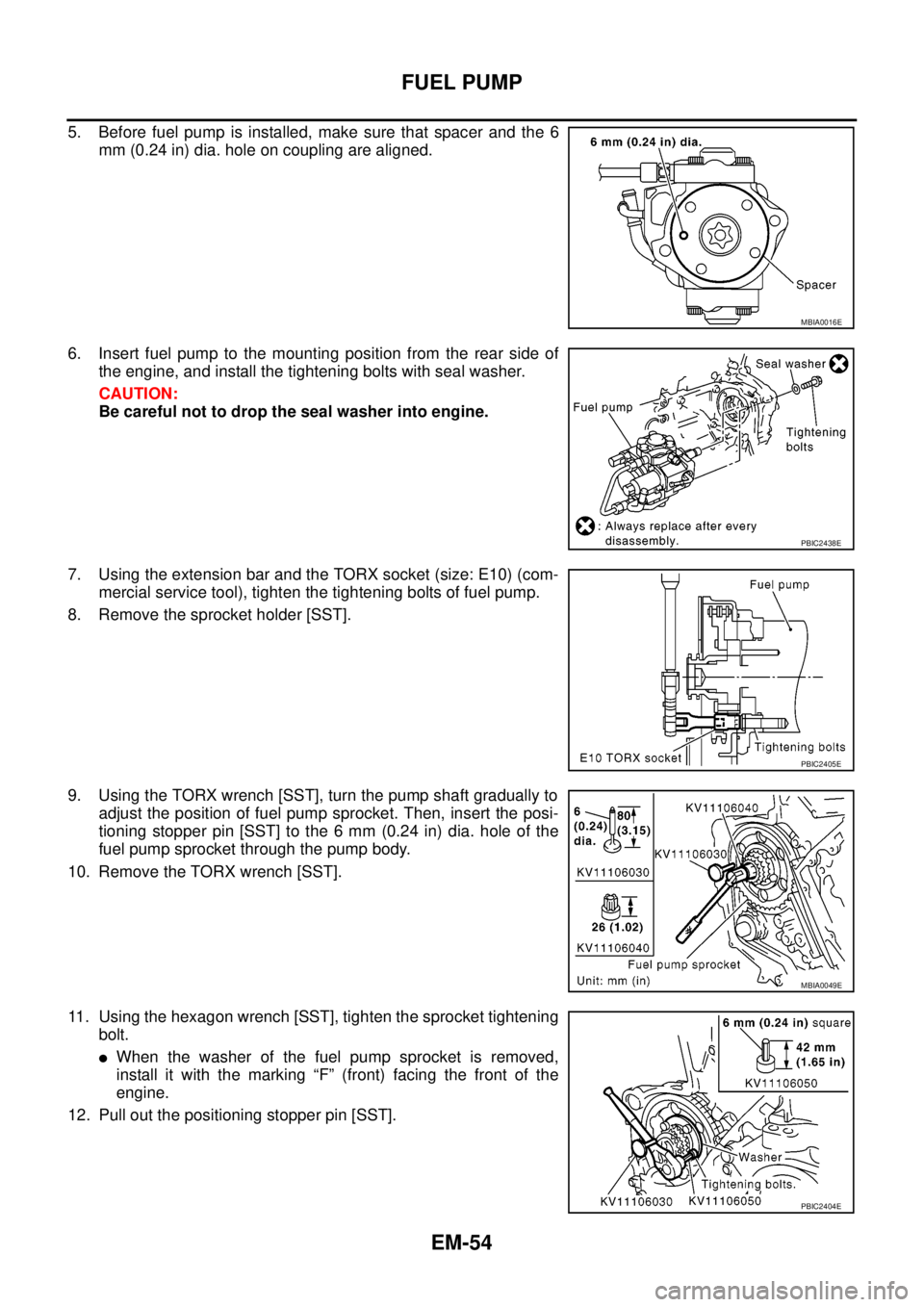
5. Before fuel pump is installed, make sure that spacer and the 6
mm (0.24 in) dia. hole on coupling are aligned.
6. Insert fuel pump to the mounting position from the rear side of
the engine, and install the tightening bolts with seal washer.
CAUTION:
Be careful not to drop the seal washer into engine.
7. Using the extension bar and the TORX socket (size: E10) (com-
mercial service tool), tighten the tightening bolts of fuel pump.
8. Remove the sprocket holder [SST].
9. Using the TORX wrench [SST], turn the pump shaft gradually to
adjust the position of fuel pump sprocket. Then, insert the posi-
tioning stopper pin [SST] to the 6 mm (0.24 in) dia. hole of the
fuel pump sprocket through the pump body.
10. Remove the TORX wrench [SST].
11. Using the hexagon wrench [SST], tighten the sprocket tightening
bolt.
lWhen the washer of the fuel pump sprocket is removed,
install it with the marking “F” (front) facing the front of the
engine.
12. Pull out the positioning stopper pin [SST].
MBIA0016E
PBIC2438E
PBIC2405E
MBIA0049E
PBIC2404E
Page 1464 of 3171
EM-82
PRIMARY TIMING CHAIN
12. Remove chain tensioner.
lWhen removing chain tensioner, push the plunger of chain
tensioner and keep it pressed with a push pin, etc.
13. Remove slack guide.
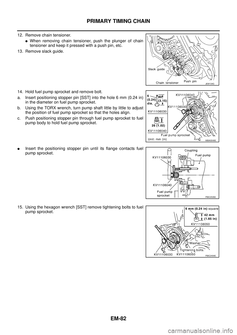
14. Hold fuel pump sprocket and remove bolt.
a. Insert positioning stopper pin [SST] into the hole 6 mm (0.24 in)
in the diameter on fuel pump sprocket.
b. Using the TORX wrench, turn pump shaft little by little to adjust
the position of fuel pump sprocket so that the holes align.
c. Push positioning stopper pin through fuel pump sprocket to fuel
pump body to hold fuel pump sprocket.
lInsert the positioning stopper pin until its flange contacts fuel
pump sprocket.
15. Using the hexagon wrench [SST] remove tightening bolts to fuel
pump sprocket.
JEM134G
MBIA0049E
PBIC2535E
PBIC2404E
Page 1469 of 3171
PRIMARY TIMING CHAIN
EM-87
C
D
E
F
G
H
I
J
K
L
MA
EM
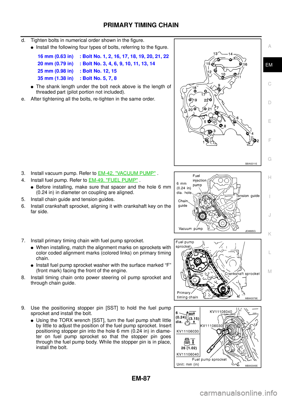
d. Tighten bolts in numerical order shown in the figure.
lInstall the following four types of bolts, referring to the figure.
lThe shank length under the bolt neck above is the length of
threaded part (pilot portion not included).
e. After tightening all the bolts, re-tighten in the same order.
3. Install vacuum pump. Refer toEM-42, "
VACUUM PUMP".
4. Install fuel pump. Refer toEM-49, "
FUEL PUMP".
lBefore installing, make sure that spacer and the hole 6 mm
(0.24 in) in diameter on coupling are aligned.
5. Install chain guide and tension guides.
6. Install crankshaft sprocket, aligning it with crankshaft key on the
far side.
7. Install primary timing chain with fuel pump sprocket.
lWhen installing, match the alignment marks on sprockets with
color coded alignment marks (colored links) on primary timing
chain.
lInstall fuel pump sprocket washer with the surface marked “F”
(front mark) facing the front of the engine.
8. Install timing chain onto power steering oil pump sprocket and
through chain guide.
9. Use the positioning stopper pin [SST] to hold the fuel pump
sprocket and install the bolt.
lUsing the TORX wrench [SST], turn the fuel pump shaft little
by little to adjust the position of the fuel pump sprocket. Insert
positioning stopper pin into the hole 6 mm (0.24 in) in diame-
ter on fuel pump sprocket so that the stopper pin goes
through the fuel pump body. While the stopper pin is in place,
install the bolt.16 mm (0.63 in) : Bolt No. 1, 2, 16, 17, 18, 19, 20, 21, 22
20mm(0.79in) :BoltNo.3,4,6,9,10,11,13,14
25 mm (0.98 in) : Bolt No. 12, 15
35 mm (1.38 in) : Bolt No. 5, 7, 8
SBIA0211E
JEM885G
MBIA0079E
MBIA0049E
Page 1488 of 3171
EM-106
ENGINE ASSEMBLY
ENGINE ASSEMBLY
PFP:10001
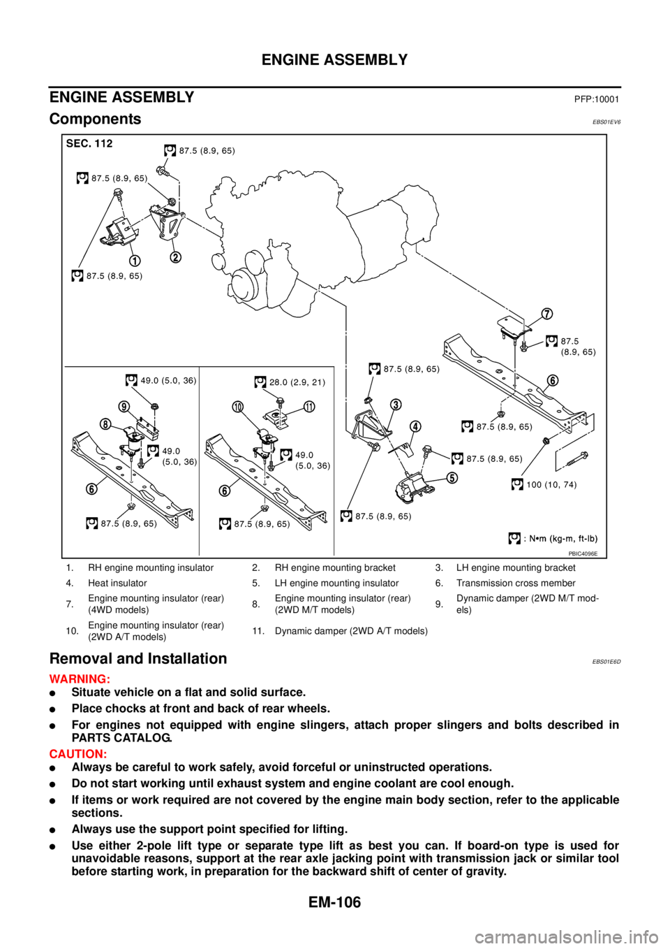
ComponentsEBS01EV6
Removal and InstallationEBS01E6D
WARNING:
lSituate vehicle on a flat and solid surface.
lPlace chocks at front and back of rear wheels.
lFor engines not equipped with engine slingers, attach proper slingers and bolts described in
PARTS CATALOG.
CAUTION:
lAlways be careful to work safely, avoid forceful or uninstructed operations.
lDo not start working until exhaust system and engine coolant are cool enough.
lIf items or work required are not covered by the engine main body section, refer to the applicable
sections.
lAlways use the support point specified for lifting.
lUse either 2-pole lift type or separate type lift as best you can. If board-on type is used for
unavoidable reasons, support at the rear axle jacking point with transmission jack or similar tool
before starting work, in preparation for the backward shift of center of gravity.
1. RH engine mounting insulator 2. RH engine mounting bracket 3. LH engine mounting bracket
4. Heat insulator 5. LH engine mounting insulator 6. Transmission cross member
7.Engine mounting insulator (rear)
(4WD models)8.Engine mounting insulator (rear)
(2WD M/T models)9.Dynamic damper (2WD M/T mod-
els)
10.Engine mounting insulator (rear)
(2WD A/T models)11. Dynamic damper (2WD A/T models)
PBIC4096E
Page 1489 of 3171
ENGINE ASSEMBLY
EM-107
C
D
E
F
G
H
I
J
K
L
MA
EM
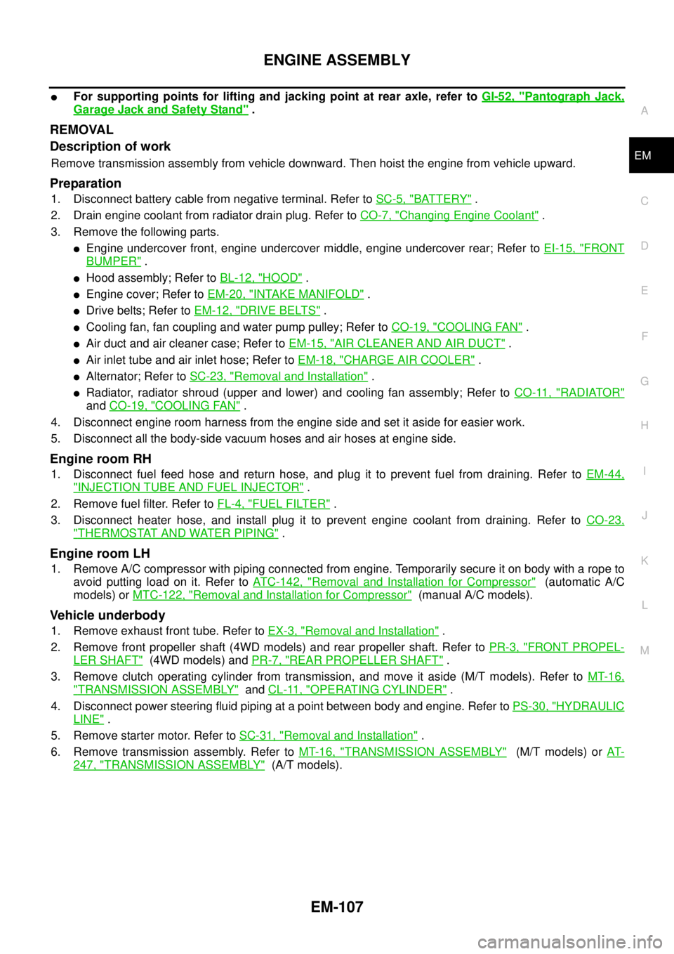
lFor supporting points for lifting and jacking point at rear axle, refer toGI-52, "Pantograph Jack,
Garage Jack and Safety Stand".
REMOVAL
Description of work
Remove transmission assembly from vehicle downward. Then hoist the engine from vehicle upward.
Preparation
1. Disconnect battery cable from negative terminal. Refer toSC-5, "BATTERY".
2. Drain engine coolant from radiator drain plug. Refer toCO-7, "
Changing Engine Coolant".
3. Remove the following parts.
lEngine undercover front, engine undercover middle, engine undercover rear; Refer toEI-15, "FRONT
BUMPER".
lHood assembly; Refer toBL-12, "HOOD".
lEngine cover; Refer toEM-20, "INTAKE MANIFOLD".
lDrive belts; Refer toEM-12, "DRIVE BELTS".
lCooling fan, fan coupling and water pump pulley; Refer toCO-19, "COOLING FAN".
lAir duct and air cleaner case; Refer toEM-15, "AIR CLEANER AND AIR DUCT".
lAir inlet tube and air inlet hose; Refer toEM-18, "CHARGE AIR COOLER".
lAlternator; Refer toSC-23, "Removal and Installation".
lRadiator, radiator shroud (upper and lower) and cooling fan assembly; Refer toCO-11, "RADIATOR"
andCO-19, "COOLING FAN".
4. Disconnect engine room harness from the engine side and set it aside for easier work.
5. Disconnect all the body-side vacuum hoses and air hoses at engine side.
Engine room RH
1. Disconnect fuel feed hose and return hose, and plug it to prevent fuel from draining. Refer toEM-44,
"INJECTION TUBE AND FUEL INJECTOR".
2. Remove fuel filter. Refer toFL-4, "
FUEL FILTER".
3. Disconnect heater hose, and install plug it to prevent engine coolant from draining. Refer toCO-23,
"THERMOSTAT AND WATER PIPING".
Engine room LH
1. Remove A/C compressor with piping connected from engine. Temporarily secure it on body with a rope to
avoid putting load on it. Refer toATC-142, "
Removal and Installation for Compressor"(automatic A/C
models) orMTC-122, "
Removal and Installation for Compressor"(manual A/C models).
Vehicle underbody
1. Remove exhaust front tube. Refer toEX-3, "Removal and Installation".
2. Remove front propeller shaft (4WD models) and rear propeller shaft. Refer toPR-3, "
FRONT PROPEL-
LER SHAFT"(4WD models) andPR-7, "REAR PROPELLER SHAFT".
3. Remove clutch operating cylinder from transmission, and move it aside (M/T models). Refer toMT-16,
"TRANSMISSION ASSEMBLY"andCL-11, "OPERATING CYLINDER".
4. Disconnect power steering fluid piping at a point between body and engine. Refer toPS-30, "
HYDRAULIC
LINE".
5. Remove starter motor. Refer toSC-31, "
Removal and Installation".
6. Remove transmission assembly. Refer toMT-16, "
TRANSMISSION ASSEMBLY"(M/T models) orAT-
247, "TRANSMISSION ASSEMBLY"(A/T models).
Page 1490 of 3171
EM-108
ENGINE ASSEMBLY
Removal
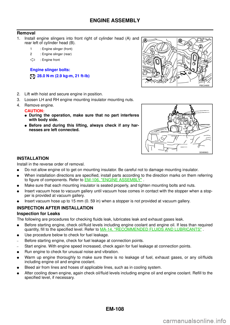
1. Install engine slingers into front right of cylinder head (A) and
rear left of cylinder head (B).
2. Lift with hoist and secure engine in position.
3. Loosen LH and RH engine mounting insulator mounting nuts.
4. Remove engine.
CAUTION:
lDuring the operation, make sure that no part interferes
with body side.
lBefore and during this lifting, always check if any har-
nesses are left connected.
INSTALLATION
Install in the reverse order of removal.
lDo not allow engine oil to get on mounting insulator. Be careful not to damage mounting insulator.
lWhen installation directions are specified, install parts according to the direction marks on them referring
to figure of components. Refer toEM-106, "
ENGINE ASSEMBLY".
lMake sure that each mounting insulator is seated properly, and tighten mounting bolts and nuts.
lInsert vacuum hose to vacuum gallery until vacuum hose comes in contact with the stopper when a stop-
per is provided at vacuum gallery.
lInsert vacuum hose up to 15 mm (0. 59 in) when a stopper is not provided at vacuum gallery.
INSPECTION AFTER INSTALLATION
Inspection for Leaks
The following are procedures for checking fluids leak, lubricates leak and exhaust gases leak.
lBefore starting engine, check oil/fluid levels including engine coolant and engine oil. If less than required
quantity, fill to the specified level. Refer toMA-14, "
RECOMMENDED FLUIDS AND LUBRICANTS".
lUse procedure below to check for fuel leakage.
–Before starting engine, check for fuel leakage at connection points.
–Start engine. With engine speed increased, check again for fuel leakage at connection points.
lRun engine to check for unusual noise and vibration.
lWarm up engine thoroughly to make sure there is no leakage of fuel, exhaust gases, or any oil/fluids
including engine oil and engine coolant.
lBleed air from lines and hoses of applicable lines, such as in cooling system.
lAfter cooling down engine, again check oil/fluid levels including engine oil and engine coolant. Refill to the
specified level, if necessary.
1 : Engine slinger (front)
2 : Engine slinger (rear)
: Engine front
Engine slinger bolts:
: 28.0 N·m (2.9 kg-m, 21 ft-lb)
PBIC3480E
SEM896G
Page 1497 of 3171
CYLINDER BLOCK
EM-115
C
D
E
F
G
H
I
J
K
L
MA
EM
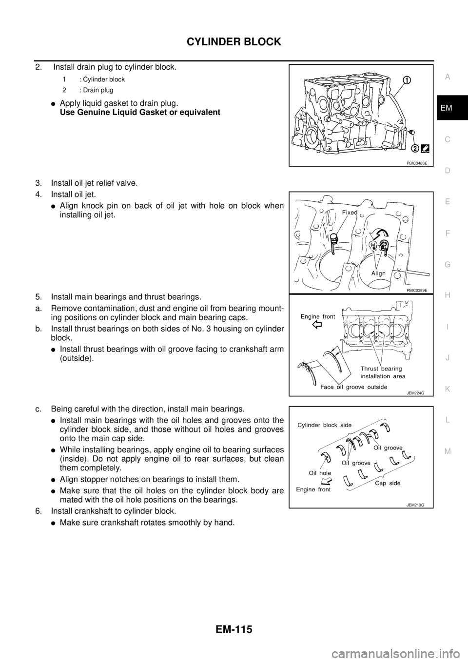
2. Install drain plug to cylinder block.
lApply liquid gasket to drain plug.
Use Genuine Liquid Gasket or equivalent
3. Install oil jet relief valve.
4. Install oil jet.
lAlign knock pin on back of oil jet with hole on block when
installing oil jet.
5. Install main bearings and thrust bearings.
a. Remove contamination, dust and engine oil from bearing mount-
ing positions on cylinder block and main bearing caps.
b. Install thrust bearings on both sides of No. 3 housing on cylinder
block.
lInstall thrust bearings with oil groove facing to crankshaft arm
(outside).
c. Being careful with the direction, install main bearings.
lInstall main bearings with the oil holes and grooves onto the
cylinder block side, and those without oil holes and grooves
onto the main cap side.
lWhile installing bearings, apply engine oil to bearing surfaces
(inside). Do not apply engine oil to rear surfaces, but clean
them completely.
lAlign stopper notches on bearings to install them.
lMake sure that the oil holes on the cylinder block body are
mated with the oil hole positions on the bearings.
6. Install crankshaft to cylinder block.
lMake sure crankshaft rotates smoothly by hand.
1 : Cylinder block
2 : Drain plug
PBIC3483E
PBIC0389E
JEM224G
JEM213G
Page 1632 of 3171
GI-10
HOW TO USE THIS MANUAL
Components
EAS001GW
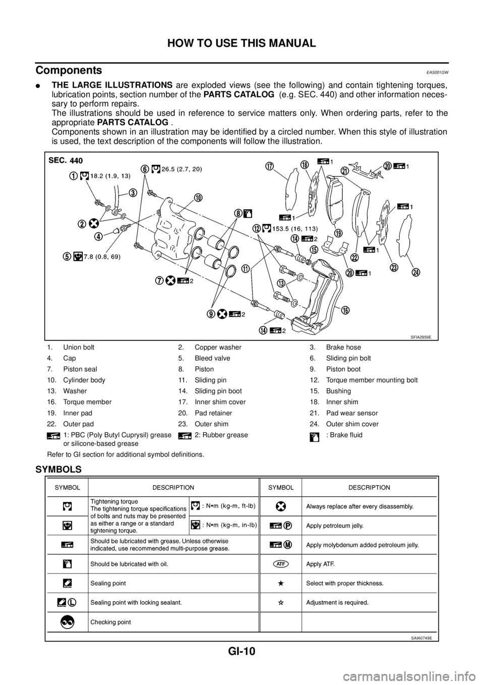
lTHE LARGE ILLUSTRATIONSare exploded views (see the following) and contain tightening torques,
lubrication points, section number of thePARTS CATALOG(e.g. SEC. 440) and other information neces-
sary to perform repairs.
The illustrations should be used in reference to service matters only. When ordering parts, refer to the
appropriatePARTS CATALOG.
Components shown in an illustration may be identified by a circled number. When this style of illustration
is used, the text description of the components will follow the illustration.
SYMBOLS
1. Union bolt 2. Copper washer 3. Brake hose
4. Cap 5. Bleed valve 6. Sliding pin bolt
7. Piston seal 8. Piston 9. Piston boot
10. Cylinder body 11. Sliding pin 12. Torque member mounting bolt
13. Washer 14. Sliding pin boot 15. Bushing
16. Torque member 17. Inner shim cover 18. Inner shim
19. Inner pad 20. Pad retainer 21. Pad wear sensor
22. Outer pad 23. Outer shim 24. Outer shim cover
1: PBC (Poly Butyl Cuprysil) grease
or silicone-based grease2: Rubber grease : Brake fluid
Refer to GI section for additional symbol definitions.
SFIA2959E
SAIA0749E