2005 NISSAN NAVARA body
[x] Cancel search: bodyPage 1639 of 3171
HOW TO USE THIS MANUAL
GI-17
C
D
E
F
G
H
I
J
K
L
MB
GI
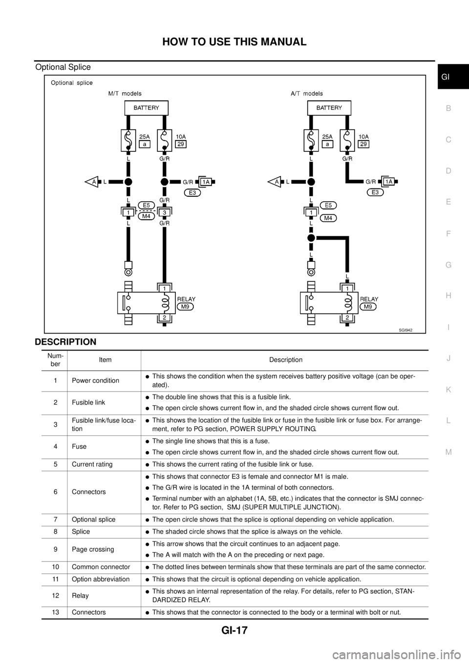
Optional Splice
DESCRIPTION
SGI942
Num-
berItem Description
1 Power condition
lThis shows the condition when the system receives battery positive voltage (can be oper-
ated).
2 Fusible link
lThe double line shows that this is a fusible link.
lThe open circle shows current flow in, and the shaded circle shows current flow out.
3Fusible link/fuse loca-
tion
lThis shows the location of the fusible link or fuse in the fusible link or fuse box. For arrange-
ment, refer to PG section, POWER SUPPLY ROUTING.
4Fuse
lThe single line shows that this is a fuse.
lThe open circle shows current flow in, and the shaded circle shows current flow out.
5 Current rating
lThis shows the current rating of the fusible link or fuse.
6 Connectors
lThis shows that connector E3 is female and connector M1 is male.
lThe G/R wire is located in the 1A terminal of both connectors.
lTerminal number with an alphabet (1A, 5B, etc.) indicates that the connector is SMJ connec-
tor. Refer to PG section, SMJ (SUPER MULTIPLE JUNCTION).
7 Optional splice
lThe open circle shows that the splice is optional depending on vehicle application.
8Splice
lThe shaded circle shows that the splice is always on the vehicle.
9 Page crossing
lThis arrow shows that the circuit continues to an adjacent page.
lThe A will match with the A on the preceding or next page.
10 Common connector
lThe dotted lines between terminals show that these terminals are part of the same connector.
11 Option abbreviation
lThis shows that the circuit is optional depending on vehicle application.
12 Relay
lThis shows an internal representation of the relay. For details, refer to PG section, STAN-
DARDIZED RELAY.
13 Connectors
lThis shows that the connector is connected to the body or a terminal with bolt or nut.
Page 1653 of 3171
SERVICE INFORMATION FOR ELECTRICAL INCIDENT
GI-31
C
D
E
F
G
H
I
J
K
L
MB
GI
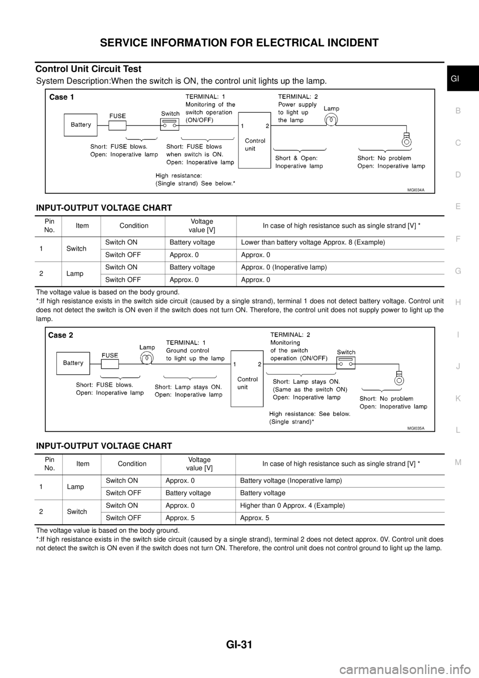
Control Unit Circuit Test
System Description:When the switch is ON, the control unit lights up the lamp.
INPUT-OUTPUT VOLTAGE CHART
The voltage value is based on the body ground.
*:If high resistance exists in the switch side circuit (caused by a single strand), terminal 1 does not detect battery voltage. Control unit
does not detect the switch is ON even if the switch does not turn ON. Therefore, the control unit does not supply power to light up the
lamp.
INPUT-OUTPUT VOLTAGE CHART
The voltage value is based on the body ground.
*:If high resistance exists in the switch side circuit (caused by a single strand), terminal 2 does not detect approx. 0V. Control unit does
not detect the switch is ON even if the switch does not turn ON. Therefore, the control unit does not control ground to light up the lamp.
MGI034A
Pin
No.Item ConditionVoltage
value [V]In case of high resistance such as single strand [V] *
1 SwitchSwitch ON Battery voltage Lower than battery voltage Approx. 8 (Example)
Switch OFF Approx. 0 Approx. 0
2LampSwitch ON Battery voltage Approx. 0 (Inoperative lamp)
Switch OFF Approx. 0 Approx. 0
MGI035A
Pin
No.Item ConditionVoltage
value [V]In case of high resistance such as single strand [V] *
1 LampSwitch ON Approx. 0 Battery voltage (Inoperative lamp)
Switch OFF Battery voltage Battery voltage
2SwitchSwitch ON Approx. 0 Higher than 0 Approx. 4 (Example)
Switch OFF Approx. 5 Approx. 5
Page 1674 of 3171
GI-52
LIFTING POINT
LIFTING POINT
PFP:00000
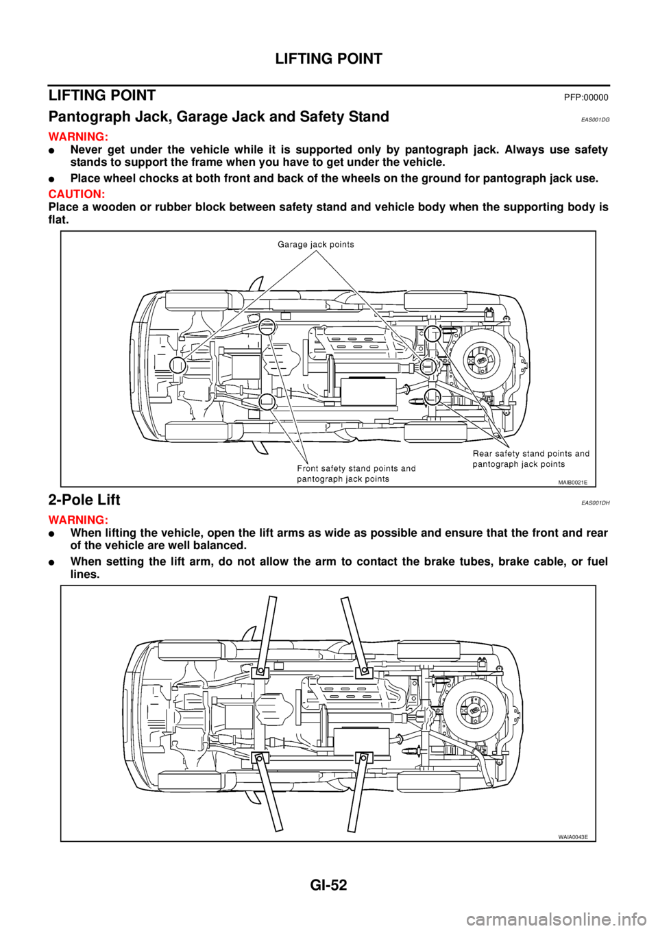
Pantograph Jack, Garage Jack and Safety StandEAS001DG
WARNING:
lNever get under the vehicle while it is supported only by pantograph jack. Always use safety
stands to support the frame when you have to get under the vehicle.
lPlace wheel chocks at both front and back of the wheels on the ground for pantograph jack use.
CAUTION:
Place a wooden or rubber block between safety stand and vehicle body when the supporting body is
flat.
2-Pole LiftEAS001DH
WARNING:
lWhen lifting the vehicle, open the lift arms as wide as possible and ensure that the front and rear
of the vehicle are well balanced.
lWhen setting the lift arm, do not allow the arm to contact the brake tubes, brake cable, or fuel
lines.
MAIB0021E
WAIA0043E
Page 1676 of 3171
GI-54
TOW TRUCK TOWING
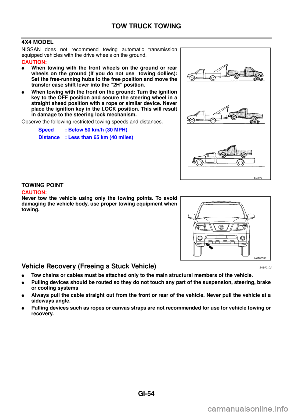
4X4 MODEL
NISSAN does not recommend towing automatic transmission
equipped vehicles with the drive wheels on the ground.
CAUTION:
lWhen towing with the front wheels on the ground or rear
wheels on the ground (If you do not use towing dollies):
Set the free-running hubs to the free position and move the
transfer case shift lever into the “2H” position.
lWhen towing with the front on the ground: Turn the ignition
key to the OFF position and secure the steering wheel in a
straight ahead position with a rope or similar device. Never
place the ignition key in the LOCK position. This will result
in damage to the steering lock mechanism.
Observe the following restricted towing speeds and distances.
TOWING POINT
CAUTION:
Never tow the vehicle using only the towing points. To avoid
damaging the vehicle body, use proper towing equipment when
towing.
Vehicle Recovery (Freeing a Stuck Vehicle)EAS001DJ
lTow chains or cables must be attached only to the main structural members of the vehicle.
lPulling devices should be routed so they do not touch any part of the suspension, steering, brake
or cooling systems
lAlways pull the cable straight out from the front or rear of the vehicle. Never pull the vehicle at a
sideways angle.
lPulling devices such as ropes or canvas straps are not recommended for use for vehicle towing or
recovery.Speed : Below 50 km/h (30 MPH)
Distance : Less than 65 km (40 miles)
SGI973
LAIA0053E
Page 1678 of 3171
GI-56
IDENTIFICATION INFORMATION
IDENTIFICATION INFORMATION
PFP:00010
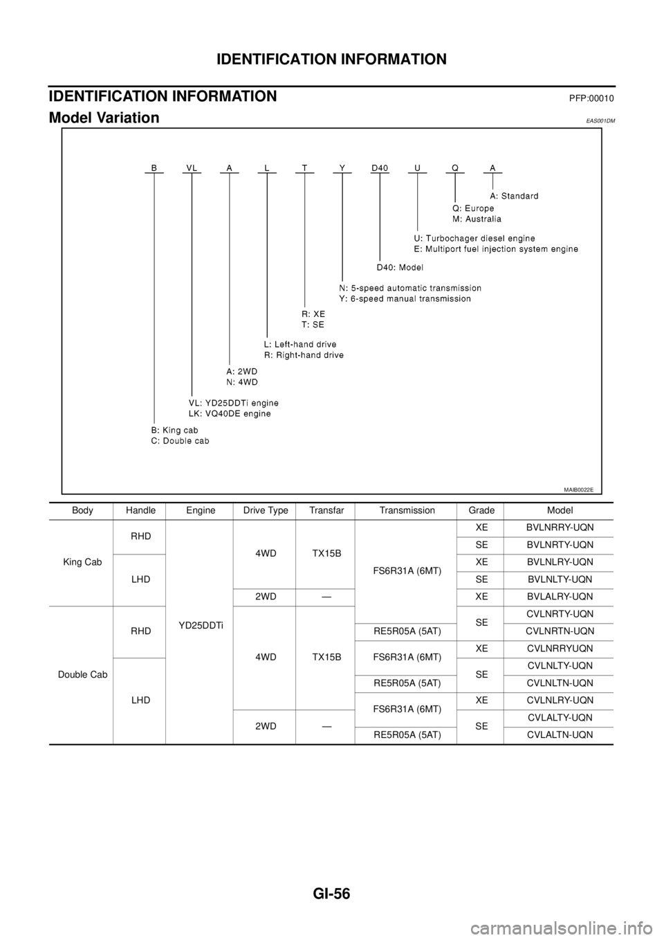
Model VariationEAS001DM
MAIB0022E
Body Handle Engine Drive Type Transfar Transmission Grade Model
King CabRHD
YD25DDTi4WD TX15B
FS6R31A (6MT)XE BVLNRRY-UQN
SE BVLNRTY-UQN
LHDXE BVLNLRY-UQN
SE BVLNLTY-UQN
2WD — XE BVLALRY-UQN
Double CabRHD
4WD TX15BSECVLNRTY-UQN
RE5R05A (5AT) CVLNRTN-UQN
FS6R31A (6MT)XE CVLNRRYUQN
LHDSECVLNLTY-UQN
RE5R05A (5AT) CVLNLTN-UQN
FS6R31A (6MT)XE CVLNLRY-UQN
2WD — SECVLALTY-UQN
RE5R05A (5AT) CVLALTN-UQN
Page 1685 of 3171

TERMINOLOGY
GI-63
C
D
E
F
G
H
I
J
K
L
MB
GI
Nonvolatile random access memory NVRAM ***
On board diagnostic system OBD system Self-diagnosis
Open loop OL Open loop
Oxidation catalyst OC Catalyst
Oxidation catalytic converter system OC system ***
Oxygen sensor O2S Exhaust gas sensor
Park position switch *** Park switch
Park/neutral position switch PNP switchPark/neutral switch
Inhibitor switch
Neutral position switch
Periodic trap oxidizer system PTOX system ***
Positive crankcase ventilation PCV Positive crankcase ventilation
Positive crankcase ventilation valve PCV valve PCV valve
Powertrain control module PCM ***
Programmable read only memory PROM ***
Pulsed secondary air injection control sole-
noid valvePAIRC solenoid valve AIV control solenoid valve
Pulsed secondary air injection system PAIR system Air induction valve (AIV) control
Pulsed secondary air injection valve PAIR valve Air induction valve
Random access memory RAM ***
Read only memory ROM ***
Scan tool ST ***
Secondary air injection pump AIR pump ***
Secondary air injection system AIR system ***
Sequential multiport fuel injection system SFI system Sequential fuel injection
Service reminder indicator SRI ***
Simultaneous multiport fuel injection sys-
tem*** Simultaneous fuel injection
Smoke puff limiter system SPL system ***
Supercharger SC ***
Supercharger bypass SCB ***
System readiness test SRT ***
Thermal vacuum valve TVV Thermal vacuum valve
Three way catalyst TWC Catalyst
Three way catalytic converter system TWC system ***
Three way + oxidation catalyst TWC + OC Catalyst
Three way + oxidation catalytic converter
systemTWC + OC system ***
Throttle body TBThrottle chamber
SPI body
Throttle body fuel injection system TBI system Fuel injection control
Throttle position TP Throttle position
Throttle position sensor TPS Throttle sensor
Throttle position switch TP switch Throttle switch
Torque converter clutch solenoid valve TCC solenoid valveLock-up cancel solenoid
Lock-up solenoid NEW TERMNEW ACRONYM /
ABBREVIATIONOLD TERM
Page 1687 of 3171

GW-1
GLASSES, WINDOW SYSTEM & MIRRORS
IBODY
CONTENTS
C
D
E
F
G
H
J
K
L
M
SECTIONGW
A
B
GW
GLASSES, WINDOW SYSTEM & MIRRORS
PRECAUTIONS .......................................................... 3
Precautions for Supplemental Restraint System
(SRS)“AIRBAG”and“SEATBELTPRE-TEN-
SIONER” .................................................................. 3
Precautions for Procedures without Cowl Top Cover..... 3
Handling for Adhesive and Primer ........................... 3
Trouble Diagnosis Precaution .................................. 3
PREPARATION ........................................................... 4
Commercial Service Tool ......................................... 4
SQUEAK AND RATTLE TROUBLE DIAGNOSES..... 5
Work Flow ................................................................ 5
CUSTOMER INTERVIEW ..................................... 5
DUPLICATE THE NOISE AND TEST DRIVE ....... 6
CHECK RELATED SERVICE BULLETINS ........... 6
LOCATE THE NOISE AND IDENTIFY THE
ROOT CAUSE ...................................................... 6
REPAIR THE CAUSE ........................................... 6
CONFIRM THE REPAIR ....................................... 7
Generic Squeak and Rattle Troubleshooting ........... 7
INSTRUMENT PANEL .......................................... 7
CENTER CONSOLE ............................................. 7
DOORS ................................................................. 7
TRUNK .................................................................. 8
SUNROOF/HEADLINING ..................................... 8
SEATS ................................................................... 8
UNDERHOOD ....................................................... 8
Diagnostic Worksheet .............................................. 9
WINDSHIELD GLASS ...............................................11
Removal and Installation ......................................... 11
REMOVAL ............................................................ 11
INSTALLATION .................................................... 11
POWER WINDOW SYSTEM .................................... 15
Component Parts and Harness Connector Location... 15
System Description ................................................ 15
MANUAL OPERATION ....................................... 16
AUTO OPERATION ............................................ 18
POWER WINDOW LOCK ................................... 18
DRIVER WINDOW ANTI-PINCH FUNCTION ..... 18
Schematic .............................................................. 19Wiring Diagram – WINDOW – ................................ 20
Terminal and Reference Value for Power Window
Main Switch ............................................................ 24
Terminal and Reference Value for Each Door's
Power Window Switch ............................................ 24
Terminal and Reference Value for BCM ................. 25
Work Flow ............................................................... 25
Trouble Diagnosis Symptom Chart ......................... 25
BCM Power Supply and Ground Circuit Check ...... 26
Power Window Main Switch Power Supply and
Ground Circuit Check ............................................. 27
Driver Side Power Window Motor Check ............... 28
Passenger Side Power Window Motor Circuit
Check ..................................................................... 29
Rear LH Power Window Motor Circuit Check ......... 30
Rear RH Power Window Motor Circuit Check ........ 31
Passenger Side Power Window Circuit Check ....... 31
Rear LH Power Window Circuit Check ................... 32
Rear RH Power Window Circuit Check .................. 33
Power Window Switch Check 1 .............................. 33
Power Window Switch Check 2 .............................. 34
FRONT DOOR GLASS AND REGULATOR ............. 35
Removal and Installation ........................................ 35
DOOR GLASS ..................................................... 35
REGULATOR ASSEMBLY .................................. 36
Disassembly and Assembly .................................... 37
REGULATOR ASSEMBLY .................................. 37
Inspection after Installation ..................................... 37
FITTING INSPECTION ....................................... 37
RESET OPERATION ........................................... 37
REAR DOOR GLASS AND REGULATOR ............... 38
Removal and Installation ........................................ 38
DOOR GLASS ..................................................... 38
REGULATOR ASSEMBLY .................................. 39
Disassembly and Assembly .................................... 40
REGULATOR ASSEMBLY .................................. 40
Inspection after Installation ..................................... 40
FITTING INSPECTION ....................................... 40
Page 1692 of 3171
GW-6
SQUEAK AND RATTLE TROUBLE DIAGNOSES
DUPLICATE THE NOISE AND TEST DRIVE
If possible, drive the vehicle with the customer until the noise is duplicated. Note any additional information on
the Diagnostic Worksheet regarding the conditions or location of the noise. This information can be used to
duplicate the same conditions when you confirm the repair.
If the noise can be duplicated easily during the test drive, to help identify the source of the noise, try to dupli-
cate the noise with the vehicle stopped by doing one or all of the following:
1) Close a door.
2) Tap or push/pull around the area where the noise appears to be coming from.
3) Rev the engine.
4) Use a floor jack to recreate vehicle “twist”.
5) At idle, apply engine load (electrical load, half-clutch on M/T model, drive position on A/T model).
6) Raise the vehicle on a hoist and hit a tire with a rubber hammer.
lDrive the vehicle and attempt to duplicate the conditions the customer states exist when the noise occurs.
lIf it is difficult to duplicate the noise, drive the vehicle slowly on an undulating or rough road to stress the
vehicle body.
CHECK RELATED SERVICE BULLETINS
After verifying the customer concern or symptom, check ASIST for Technical Service Bulletins (TSBs) related
to that concern or symptom.
If a TSB relates to the symptom, follow the procedure to repair the noise.
LOCATE THE NOISE AND IDENTIFY THE ROOT CAUSE
1. Narrow down the noise to a general area. To help pinpoint the source of the noise, use a listening tool
(Engine Ear or mechanics stethoscope).
2. Narrowdownthenoisetoamorespecificareaandidentifythecauseofthenoiseby:
lremoving the components in the area that you suspect the noise is coming from.
Do not use too much force when removing clips and fasteners, otherwise clips and fastener can be broken
or lost during the repair, resulting in the creation of new noise.
ltapping or pushing/pulling the component that you suspect is causing the noise.
Do not tap or push/pull the component with excessive force, otherwise the noise will be eliminated only
temporarily.
lfeeling for a vibration with your hand by touching the component(s) that you suspect is (are) causing the
noise.
lplacing a piece of paper between components that you suspect are causing the noise.
llooking for loose components and contact marks.
Refer toGW-7, "
Generic Squeak and Rattle Troubleshooting".
REPAIR THE CAUSE
lIf the cause is a loose component, tighten the component securely.
lIf the cause is insufficient clearance between components:
–separate components by repositioning or loosening and retightening the component, if possible.
–insulate components with a suitable insulator such as urethane pads, foam blocks, felt cloth tape or ure-
thane tape are available through your authorized Nissan Parts Department.
CAUTION:
Do not use excessive force as many components are constructed of plastic and may be damaged.
NOTE:
Always check with the Parts Department for the latest parts information.
Each item can be ordered separately as needed.
URETHANE PADS [1.5 mm (0.059 in) thick]
Insulates connectors, harness, etc.
76268-9E005: 100´135 mm (3.94´5.31 in)/76884-71L01: 60´85 mm (2.36´3.35 in)/76884-71L02: 15´
25 mm (0.59´0.98 in)
INSULATOR (Foam blocks)
Insulates components from contact. Can be used to fill space behind a panel.
73982-9E000: 45 mm (1.77 in) thick, 50´50 mm (1.97´1.97 in)/73982-50Y00: 10 mm (0.39 in) think, 50
´50 mm (1.97´1.97 in)
INSULATOR (Light foam block)
80845-71L00: 30 mm (1.18 in) thick, 30´50 mm (1.18´1.97 in)