2005 NISSAN NAVARA body
[x] Cancel search: bodyPage 1270 of 3171
EC-290
DTC P2147, P2148 FUEL INJECTOR CIRCUIT
Diagnostic Procedure
EBS01KLF
1.CHECK GROUND CONNECTIONS
1. Turn ignition switch OFF.
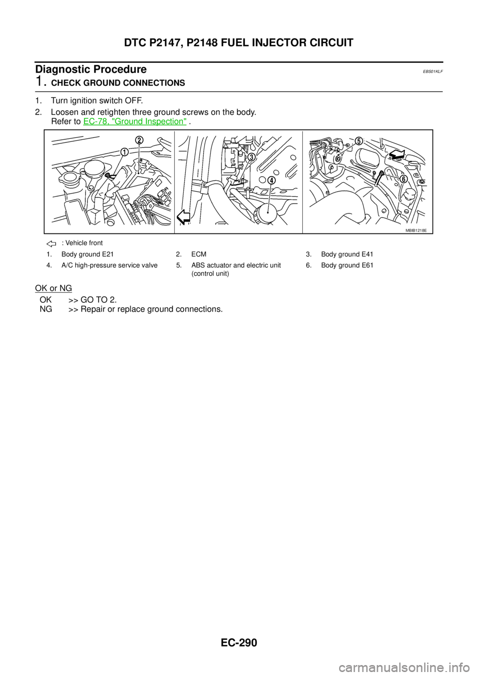
2. Loosen and retighten three ground screws on the body.
Refer toEC-78, "
Ground Inspection".
OK or NG
OK >> GO TO 2.
NG >> Repair or replace ground connections.
: Vehicle front
1. Body ground E21 2. ECM 3. Body ground E41
4. A/C high-pressure service valve 5. ABS actuator and electric unit
(control unit)6. Body ground E61
MBIB1218E
Page 1278 of 3171
EC-298
GLOW CONTROL SYSTEM
4.CHECK GLOW CONTROL SYSTEM OVERALL FUNCTION
With CONSULT-II
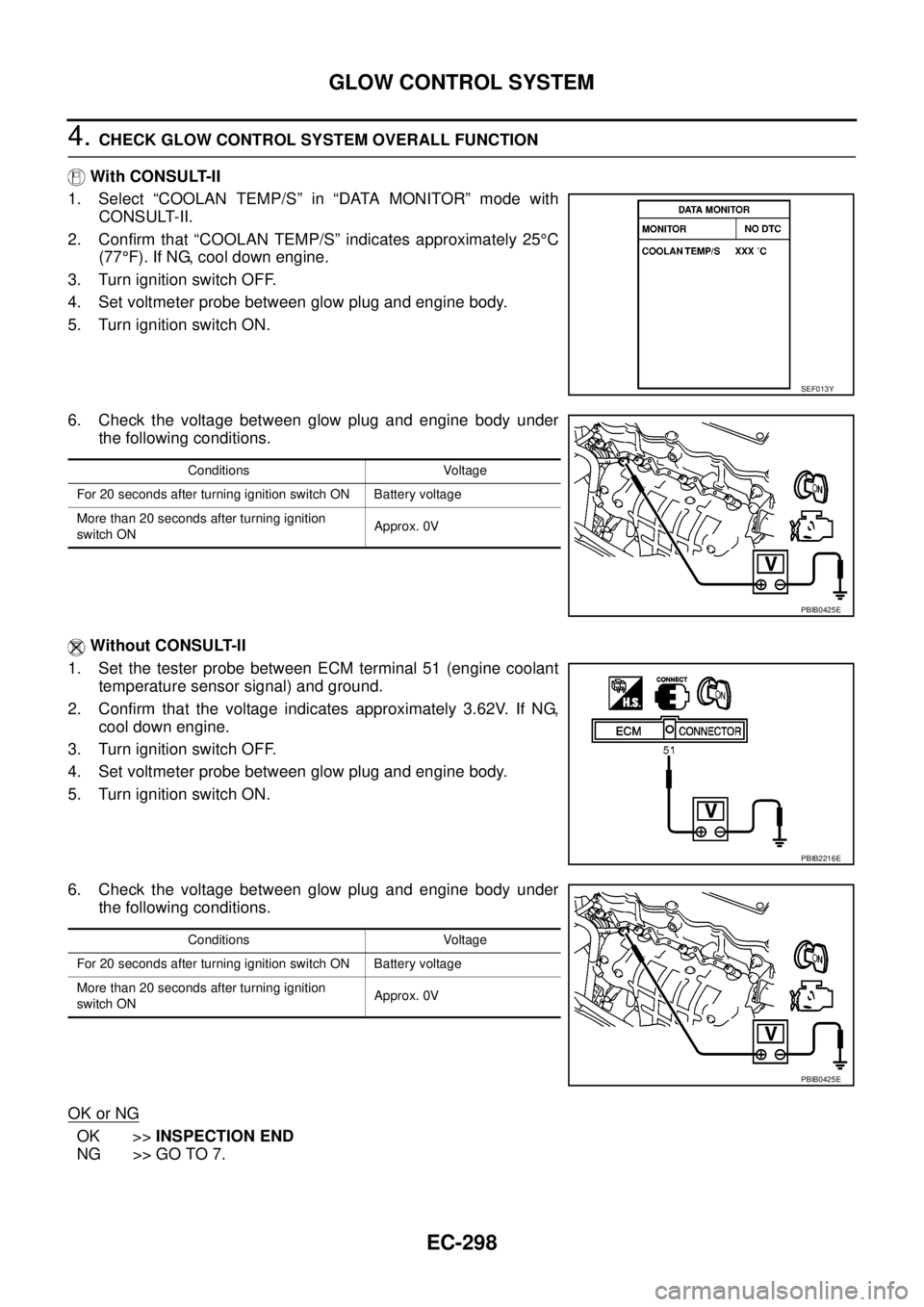
1. Select “COOLAN TEMP/S” in “DATA MONITOR” mode with
CONSULT-II.
2. Confirm that “COOLAN TEMP/S” indicates approximately 25°C
(77°F). If NG, cool down engine.
3. Turn ignition switch OFF.
4. Set voltmeter probe between glow plug and engine body.
5. Turn ignition switch ON.
6. Check the voltage between glow plug and engine body under
the following conditions.
Without CONSULT-II
1. Set the tester probe between ECM terminal 51 (engine coolant
temperature sensor signal) and ground.
2. Confirm that the voltage indicates approximately 3.62V. If NG,
cool down engine.
3. Turn ignition switch OFF.
4. Set voltmeter probe between glow plug and engine body.
5. Turn ignition switch ON.
6. Check the voltage between glow plug and engine body under
the following conditions.
OK or NG
OK >>INSPECTION END
NG >> GO TO 7.
SEF013Y
Conditions Voltage
For 20 seconds after turning ignition switch ON Battery voltage
More than 20 seconds after turning ignition
switch ONApprox. 0V
PBIB0425E
PBIB2216E
Conditions Voltage
For 20 seconds after turning ignition switch ON Battery voltage
More than 20 seconds after turning ignition
switch ONApprox. 0V
PBIB0425E
Page 1307 of 3171
REFRIGERANT PRESSURE SENSOR
EC-327
C
D
E
F
G
H
I
J
K
L
MA
EC
Diagnostic ProcedureEBS01KMJ
1.CHECK REFRIGERANT PRESSURE SENSOR OVERALL FUNCTION
1. Start engine and warm it up to normal operating temperature.
2. Turn A/C switch and blower switch ON.
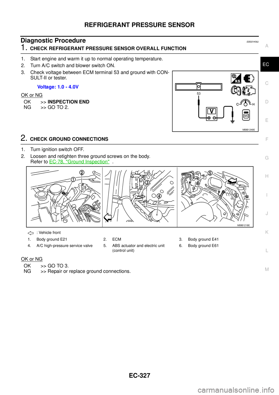
3. Check voltage between ECM terminal 53 and ground with CON-
SULT-II or tester.
OK or NG
OK >>INSPECTION END
NG >> GO TO 2.
2.CHECK GROUND CONNECTIONS
1. Turn ignition switch OFF.
2. Loosen and retighten three ground screws on the body.
Refer toEC-78, "
Ground Inspection".
OK or NG
OK >> GO TO 3.
NG >> Repair or replace ground connections.Voltage: 1.0 - 4.0V
MBIB1248E
: Vehicle front
1. Body ground E21 2. ECM 3. Body ground E41
4. A/C high-pressure service valve 5. ABS actuator and electric unit
(control unit)6. Body ground E61
MBIB1218E
Page 1339 of 3171
EI-1
EXTERIOR & INTERIOR
IBODY
CONTENTS
C
D
E
F
G
H
J
K
L
M
SECTIONEI
A
B
EI
EXTERIOR & INTERIOR
PRECAUTIONS .......................................................... 3
Service Notice .......................................................... 3
Precautions for Supplemental Restraint System
(SRS)“AIRBAG”and“SEATBELTPRE-TEN-
SIONER” .................................................................. 3
Precautions for SRS “AIR BAG” and “SEAT BELT
PRE-TENSIONER” Service ..................................... 3
Precautions for Procedures without Cowl Top Cover..... 4
PREPARATION ........................................................... 5
Commercial Service Tools ........................................ 5
SQUEAK AND RATTLE TROUBLE DIAGNOSES..... 6
Work Flow ................................................................ 6
CUSTOMER INTERVIEW ..................................... 6
DUPLICATE THE NOISE AND TEST DRIVE ....... 7
CHECK RELATED SERVICE BULLETINS ........... 7
LOCATE THE NOISE AND IDENTIFY THE
ROOT CAUSE ...................................................... 7
REPAIR THE CAUSE ........................................... 7
CONFIRM THE REPAIR ....................................... 7
Generic Squeak and Rattle Troubleshooting ........... 7
INSTRUMENT PANEL .......................................... 7
CENTER CONSOLE ............................................. 8
DOORS ................................................................. 8
TRUNK .................................................................. 8
SUNROOF/HEADLINING ..................................... 8
OVERHEAD CONSOLE (FRONT AND REAR)..... 8
SEATS ................................................................... 9
UNDERHOOD ....................................................... 9
Diagnostic Worksheet ............................................ 10
CLIP AND FASTENER ............................................. 12
Clip and Fastener ................................................... 12
FRONT BUMPER ..................................................... 15
Removal and Installation ........................................ 15
FRONT BUMPER ............................................... 15
REAR BUMPER ....................................................... 17
Removal and Installation ........................................ 17
REMOVAL ........................................................... 17
INSTALLATION ................................................... 18FRONT GRILLE ........................................................ 19
Removal and Installation ........................................ 19
REMOVAL ........................................................... 19
INSTALLATION ................................................... 19
COWL TOP ............................................................... 20
Removal and Installation ........................................ 20
REMOVAL ........................................................... 20
INSTALLATION ................................................... 20
FENDER PROTECTOR ............................................ 21
Components ........................................................... 21
Removal and Installation of Front Fender Protector... 22
REMOVAL ........................................................... 22
INSTALLATION ................................................... 22
Removal and Installation of Rear Fender Protector... 22
REMOVAL ........................................................... 22
INSTALLATION ................................................... 22
MUDGUARD ............................................................. 23
Removal and Installation ........................................ 23
RUNNING BOARDS ................................................. 24
Removal and Installation ........................................ 24
REMOVAL ........................................................... 25
INSTALLATION ................................................... 25
ROOF RACK ............................................................. 26
Removal and Installation ........................................ 26
REMOVAL ........................................................... 26
INSTALLATION ................................................... 26
DOOR OUTSIDE MOLDING ..................................... 27
Removal and Installation ........................................ 27
FRONT DOOR OUTSIDE MOLDING .................. 27
SIDE GUARD MOLDING .......................................... 28
Removal and Installation ........................................ 28
REMOVAL ........................................................... 29
INSTALLATION ................................................... 29
DOOR FINISHER ...................................................... 30
Removal and Installation ........................................ 30
FRONT DOOR .................................................... 30
REAR DOOR - DOUBLE CAB ............................ 31
REAR DOOR - KING CAB .................................. 32
BODY SIDE TRIM ..................................................... 33
Components ........................................................... 33
Page 1341 of 3171
PRECAUTIONS
EI-3
C
D
E
F
G
H
J
K
L
MA
B
EI
PRECAUTIONSPFP:00001
Service NoticeEIS00DY1
lWhen removing or installing various parts, place a cloth or padding on the vehicle body to prevent
scratches.
lHandle trim, molding, instruments, grille, etc. carefully during removing or installing. Be careful not to soil
or damage them.
lApply sealing compound where necessary when installing parts.
lWhen applying sealing compound, be careful that the sealing compound does not protrude from parts.
lWhen replacing any metal parts (for example body outer panel, members, etc.), be sure to take rust pre-
vention measures.
Precautions for Supplemental Restraint System (SRS) “AIR BAG” and “SEAT
BELT PRE-TENSIONER”
EIS00DZ5
The Supplemental Restraint System such as “AIR BAG” and “SEAT BELT PRE-TENSIONER”, used along
with a front seat belt, helps to reduce the risk or severity of injury to the driver and front passenger for certain
types of collision. Information necessary to service the system safely is included in the SRS and SB section of
this Service Manual.
WARNING:
lTo avoid rendering the SRS inoperative, which could increase the risk of personal injury or death
in the event of a collision which would result in air bag inflation, all maintenance must be per-
formed by an authorized NISSAN/INFINITI dealer.
lImproper maintenance, including incorrect removal and installation of the SRS, can lead to per-
sonal injury caused by unintentional activation of the system. For removal of Spiral Cable and Air
Bag Module, see the SRS section.
lDo not use electrical test equipment on any circuit related to the SRS unless instructed to in this
Service Manual. SRS wiring harnesses can be identified by yellow and/or orange harnesses or
harness connectors.
Precautions for SRS “AIR BAG” and “SEAT BELT PRE-TENSIONER” ServiceEIS00DZ2
lDo not use electrical test equipment to check SRS circuits unless instructed to in this Service Manual.
lBefore servicing the SRS, turn ignition switch OFF, disconnect both battery cables and wait at least 3 min-
utes.
For approximately 3 minutes after the cables are removed, it is still possible for the air bag and seat belt
pre-tensioner to deploy. Therefore, do not work on any SRS connectors or wires until at least 3 minutes
have passed.
lThe air bag diagnosis sensor unit must always be installed with the arrow marks “Ü” pointing toward the
front of the vehicle for proper operation. Also check the air bag diagnosis sensor unit for cracks, deformi-
ties or rust before installation and replace as required.
lThe spiral cable must be aligned with the neutral position since its rotations are limited. Do not attempt to
turn steering wheel or column after removal of steering gear.
lHandle air bag module carefully. Always place driver and front passenger air bag modules with the pad
side facing upward and seat mounted front side air bag module standing with the stud bolt side facing
down.
lConduct self-diagnosis to check entire SRS for proper function after replacing any components.
lAfter air bag inflates, the front instrument panel assembly should be replaced if damaged.
Page 1345 of 3171
SQUEAK AND RATTLE TROUBLE DIAGNOSES
EI-7
C
D
E
F
G
H
J
K
L
MA
B
EI
DUPLICATE THE NOISE AND TEST DRIVE
If possible, drive the vehicle with the customer until the noise is duplicated. Note any additional information on
the Diagnostic Worksheet regarding the conditions or location of the noise. This information can be used to
duplicate the same conditions when you confirm the repair.
If the noise can be duplicated easily during the test drive, to help identify the source of the noise, try to dupli-
cate the noise with the vehicle stopped by doing one or all of the following:
1) Close a door.
2) Tap or push/pull around the area where the noise appears to be coming from.
3) Rev the engine.
4) Use a floor jack to recreate vehicle “twist”.
5) At idle, apply engine load (electrical load, half-clutch on M/T model, drive position on A/T model).
6) Raisethevehicleonahoistandhitatirewitharubberhammer.
lDrive the vehicle and attempt to duplicate the conditions the customer states exist when the noise occurs.
lIf it is difficult to duplicate the noise, drive the vehicle slowly on an undulating or rough road to stress the
vehicle body.
CHECK RELATED SERVICE BULLETINS
After verifying the customer concern or symptom, check ASIST for Technical Service Bulletins (TSBs) related
to that concern or symptom.
If a TSB relates to the symptom, follow the procedure to repair the noise.
LOCATE THE NOISE AND IDENTIFY THE ROOT CAUSE
1. Narrow down the noise to a general area.To help pinpoint the source of the noise, use a listening tool
(Engine Ear and mechanic's stethoscope).
2. Narrow down the noise to a more specific area and identify the cause of the noise by:
lremoving the components in the area that you suspect the noise is coming from.
Do not use too much force when removing clips and fasteners, otherwise clips and fasteners can be bro-
ken or lost during the repair, resulting in the creation of new noise.
ltapping or pushing/pulling the component that you suspect is causing the noise.
Do not tap or push/pull the component with excessive force, otherwise the noise will be eliminated only
temporarily.
lfeeling for a vibration with your hand by touching the component(s) that you suspect is (are) causing the
noise.
lplacing a piece of paper between components that you suspect are causing the noise.
llooking for loose components and contact marks.
Refer toEI-7, "
Generic Squeak and Rattle Troubleshooting".
REPAIR THE CAUSE
lIf the cause is a loose component, tighten the component securely.
lIf the cause is insufficient clearance between components:
–separate components by repositioning or loosening and retightening the component, if possible.
–insulate components with a suitable insulator such as urethane pads, foam blocks, felt cloth tape or ure-
thane tape.
CAUTION:
Do not use excessive force as many components are constructed of plastic and may be damaged.
Always check with the Parts Department for the latest parts information.
CONFIRM THE REPAIR
Confirm that the cause of a noise is repaired by test driving the vehicle. Operate the vehicle under the same
conditions as when the noise originally occurred. Refer to the notes on the Diagnostic Worksheet.
Generic Squeak and Rattle TroubleshootingEIS00DY6
Refer to Table of Contents for specific component removal and installation information.
INSTRUMENT PANEL
Most incidents are caused by contact and movement between:
1. The cluster lid A and instrument panel
2. Acrylic lens and combination meter housing
Page 1367 of 3171
SIDE GUARD MOLDING
EI-29
C
D
E
F
G
H
J
K
L
MA
B
EI
REMOVAL
CAUTION:
Never apply tack-paper adhesive remover to body panel surface finished with lacquer-based paints.
lOriginal side guard molding is affixed to body panel with double-faced adhesive tape.
1. Heat molding to between 30°and 40°C(86°to 104°F) with a heat gun.
2. Raise end of molding and cut away tape to remove molding. Remove all traces of tape.
INSTALLATION
lOn vehicles coated with Hard Clear Coat, use double-faced 3M adhesive tape Product No. 4210 or equiv-
alent, after priming with 3M primer Product No. N200, C-100 or equivalent.
lThe repair parts are also affixed with double-faced adhesive tape.
lTo re-use existing molding, clean all traces of double sided tape from the molding and apply new double-
facedtapetothemolding.
1. Clean the panel surface with isopropyl alcohol or equivalent to degrease the surface.
2. Heat the panel and molding tape surface to 30°to 40°C(86°to 104°F).
3. Remove the backing sheet from the tape surface.
lAlign the locating pin into the hole in the outer door.
lContinue aligning the pins into their corresponding holes in the outer door during installation.
4. Press ends by hand and use a roller to apply 5 kg-f (11 lbs-f) to press molding to door surface.
lApply even pressure along molding to insure proper wet out.
CAUTION:
To secure contact, do not wash vehicle for 24 hours after installation.
Page 1371 of 3171
BODY SIDE TRIM
EI-33
C
D
E
F
G
H
J
K
L
MA
B
EI
BODY SIDE TRIMPFP:76913
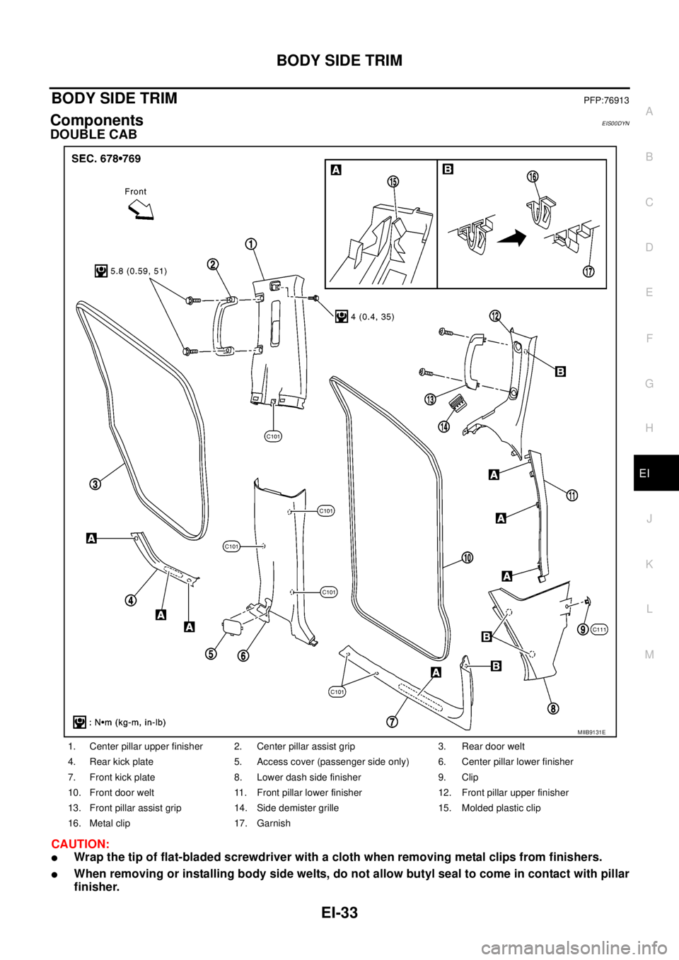
ComponentsEIS00DYN
DOUBLE CAB
CAUTION:
lWrap the tip of flat-bladed screwdriver with a cloth when removing metal clips from finishers.
lWhen removing or installing body side welts, do not allow butyl seal to come in contact with pillar
finisher.
1. Center pillar upper finisher 2. Center pillar assist grip 3. Rear door welt
4. Rear kick plate 5. Access cover (passenger side only) 6. Center pillar lower finisher
7. Front kick plate 8. Lower dash side finisher 9. Clip
10. Front door welt 11. Front pillar lower finisher 12. Front pillar upper finisher
13. Front pillar assist grip 14. Side demister grille 15. Molded plastic clip
16. Metal clip 17. Garnish
MIIB9131E