2004 SUBARU FORESTER Engine Assembly
[x] Cancel search: Engine AssemblyPage 41 of 2870
AC-39
HVAC SYSTEM (HEATER, VENTILATOR AND A/C)
Heater Cooling Unit
14.Heater Cooling Unit
A: REMOVAL
1) Disconnect the ground cable from battery.
2) Using the refrigerant recovery system, dis-
charge refrigerant.
3) Drain the engine coolant from radiator.
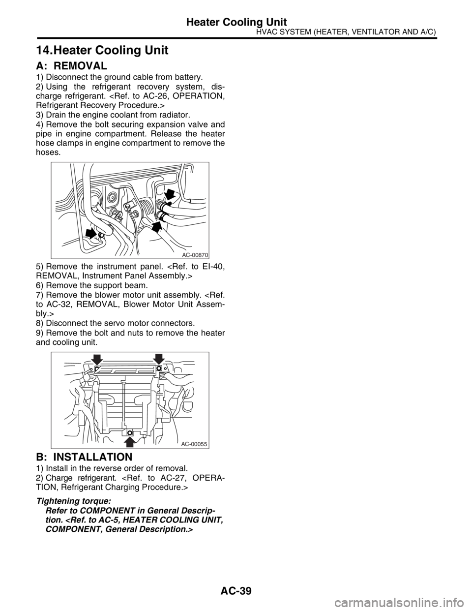
4) Remove the bolt securing expansion valve and
pipe in engine compartment. Release the heater
hose clamps in engine compartment to remove the
hoses.
5) Remove the instrument panel.
6) Remove the support beam.
7) Remove the blower motor unit assembly.
bly.>
8) Disconnect the servo motor connectors.
9) Remove the bolt and nuts to remove the heater
and cooling unit.
B: INSTALLATION
1) Install in the reverse order of removal.
2) Charge refrigerant.
Tightening torque:
Refer to COMPONENT in General Descrip-
tion.
AC-00870
AC-00055
Page 59 of 2870

AC-3
HVAC SYSTEM (AUTO A/C)(DIAGNOSTIC)
General Description
2. General Description
A: CAUTION
1) Never connect the battery in reverse polarity.
Auto A/C control module may be destroyed instant-
ly.
2) Do not disconnect the battery terminals while the
engine is running.
A large counter electromotive force will be generat-
ed in the generator, and this voltage may damage
electronic parts such as auto A/C control module,
etc.
3) Before disconnecting the connectors of each
sensor and the auto A/C control module, be sure to
turn off the ignition switch.
Auto A/C control module may be damaged.
4) Every A/C-related part is a precision part. Do not
drop them.
5) Airbag system wiring harness is routed near the
A/C control panel (auto A/C control module) and
junction box.
CAUTION:
For airbag system, yellow-colored wiring har-
ness and connectors are all used. Do not use
the electrical test equipment on these circuits.
Be careful not to damage the airbag system
wiring harness when servicing the A/C control
panel (auto A/C control module) and junction
box.
B: INSPECTION
Before performing the diagnosis, check the follow-
ing items which might affect A/C system problems.
1. BATTERY
1) Measure battery voltage and specific gravity of
electrolyte.
Standard voltage: 12 V
Specific gravity: More than 1.260
2) Check the condition of the fuses for A/C system
power supply and other fuses.
3) Check the condition of harness and harness
connector connections.
2. ASPIRATOR HOSE
1) Turn the ignition switch to ON, and press the A/
C switch.
2) Turn the temperature control dial at maximum
hot position.
3) Press the defroster switch.
4) Turn the fan speed control dial to 4th position.5) Approach a strip of paper (b) in front of the in-ve-
hicle sensor suction port (a) located in the instru-
ment lower cover, and check that air is being
sucked into the port by seeing the paper moving to-
wards port.
NOTE:
Be careful not to let the paper get sucked into port.
6) If the paper does not move at all, remove the in-
strument panel lower cover
for improper connection of the aspirator hose (a),
in-vehicle sensor and heater unit, and repair them if
necessary.
3. A/C LINE
Check the connection for A/C line (A) and lower
side high-pressure pipe.
4. CONTROL LINKAGE
1) Check the state of mode door linkage.
2) Check the state of air mix door linkage.
3) Check the state of intake door linkage.
AC-00094
(a)
(a)
(b)
AC-00065
(a)
AC-00096
(A)
Page 388 of 2870

IDI-4
INSTRUMENTATION/DRIVER INFO
Combination Meter System
B: INSPECTION
CAUTION:
When measuring voltage and resistance of the ECM, TCM, or each sensor, use a tapered pin with a
diameter of less than 0.64 mm (0.025 in) in order to avoid poor contact. Do not insert the pin more
than 2 mm (0.08 in).
1. SYMPTOM CHART
Symptom Repair order Reference
Combination meter assembly does not operate. (1) Power supply
(2) Ground circuit
GROUND CIRCUIT,
INSPECTION, Combi-
nation Meter System.>
Speedometer does not operate. (1) (MT model) Vehicle speed sensor
(AT model) TCM
(2) Harness
(3) SpeedometerMT model:
SPEED SENSOR,
INSPECTION, Combi-
nation Meter System.>
AT model:
SION CONTROL MOD-
ULE (TCM),
INSPECTION, Combi-
nation Meter System.>
Tachometer does not operate. (1) ECM
(2) Harness
(3) Tachometer
MODULE (ECM),
INSPECTION, Combi-
nation Meter System.>
Fuel gauge does not operate. (1) Fuel level sensor
(2) Harness
(3) Fuel gauge
SOR, INSPECTION,
Combination Meter
System.>
Water temperature gauge does not operate. (1) Engine coolant temperature sensor
(2) Harness
(3) Water temperature gauge
TEMPERATURE SEN-
SOR, INSPECTION,
Combination Meter
System.>
Outside temperature indicator does not operate. (1) Ambient sensor
(2) Harness
(3) Combination meter
TURE INDICATOR,
INSPECTION, Combi-
nation Meter System.>
Page 389 of 2870

IDI-5
INSTRUMENTATION/DRIVER INFO
Combination Meter System
2. CHECK POWER SUPPLY AND GROUND CIRCUIT
3. CHECK VEHICLE SPEED SENSOR
Step Check Yes No
1 CHECK POWER SUPPLY FOR COMBINA-
TION METER.
1) Remove the combination meter.
Assembly.>
2) Disconnect the combination meter harness
connector.
3) Turn the ignition switch to ON.
4) Measure the voltage between combination
meter connector and chassis ground.
Connector & terminal
(i10) No. 9 (+) — Chassis ground (
−):Is the voltage more than 10 V? Go to step 2.Check the harness
for open or short
between ignition
switch and combi-
nation meter.
2 CHECK POWER SUPPLY FOR COMBINA-
TION METER.
Measure the voltage between combination
meter connector and chassis ground.
Connector & terminal
(i10) No. 8 (+) — Chassis ground (
−):Is the voltage more than 10 V? Go to step 3.Check the harness
for open or short
between fuse and
combination
meter.
3 CHECK GROUND CIRCUIT OF COMBINA-
TION METER.
1) Turn the ignition switch to OFF.
2) Measure the resistance of harness
between combination meter connector and
chassis ground.
Connector & terminal
(i10) No. 10 — Chassis ground:Is the resistance less than 10
Ω?Replace the com-
bination meter
printed circuit.Repair the wiring
harness.
Step Check Yes No
1 CHECK VEHICLE SPEED SENSOR.
1) Lift-up the vehicle and support it with rigid
racks.
2) Remove the combination meter with har-
ness connector.
3) Drive the vehicle at a speed greater than 20
km/h (12 MPH).
Warning:
Be careful not to get caught in the running
wheels.
4) Measure the voltage between combination
meter connector and chassis ground.
Connector & terminal
(i10) No. 12 (+) — Chassis ground (
−):Is the voltage 1 V ← → 5 V? Check the speed-
ometer.
TION, Speedome-
ter.>Go to step 2.
2 CHECK VEHICLE SPEED SENSOR POWER
SUPPLY.
1) Turn the ignition switch to OFF.
2) Disconnect the vehicle speed sensor har-
ness connector.
3) Turn the ignition switch to ON.
4) Measure the voltage between vehicle
speed sensor connector and engine ground.
Connector & terminal
(B17) No. 3 (+) — Engine ground (
−):Is the voltage more than 10 V? Go to step 3.Check the harness
for open or short
between ignition
switch and vehicle
speed sensor.
Page 653 of 2870

IM-11
IMMOBILIZER (DIAGNOSTIC)
Diagnostics Chart for Immobilizer Warning Light
Step Check Yes No
1 CHECK IMMOBILIZER WARNING LIGHT.
1) Turn the ignition switch to OFF.
2) Disconnect the harness connector from
IMM ECM.
3) Connect a resistor (750 Ω) between IMM
ECM harness connector terminal No. 9 and
chassis ground.Does the immobilizer warning
light illuminate?Go to step 2.Go to step 5.
2 CHECK IMM ECM GROUND CIRCUIT.
Measure the resistance between IMM ECM
harness connector terminal and chassis
ground.
Connector & terminal
(B141) No. 2, No. 3 — Chassis ground:Is the resistance less than 10
Ω?Go to step 3.Repair the open
circuit of IMMECM
ground circuit.
3 CHECK IMM ECM IGNITION CIRCUIT.
1) Turn the ignition switch to ON. (engine
OFF.)
2) Measure the voltage between IMM ECM
harness connector terminal and chassis
ground.
Connector & terminal
(B141) No. 12 (+) — Chassis ground(
−):Is the voltage more than 10 V? Go to step 4.Check the harness
for open or short
between IMM
ECM and ignition
switch.
4 CHECK IMM ECM POWER SUPPLY CIR-
CUIT.
1) Turn the ignition switch to OFF.
2) Measure the voltage between IMM ECM
harness connector terminal and chassis
ground.
Connector & terminal
(B141) No. 10, No. 11 (+) — Chassis
ground(
−):Is the voltage more than 10 V? Replace the IMM
ECM
Control Module.>
and then replace
all ignition keys
(including the tran-
sponder). Then
perform teaching
operation. Refer to
teaching opera-
tion manual (Pub.
No. S0820GZ).Check the harness
for open or short
between IMM
ECM and fuse.
5 CHECK COMBINATION METER CIRCUIT.
1) Remove the combination meter.
2) Measure the voltage between combination
meter harness connector terminal and chassis
ground.
Connector & terminal
(i10) No. 8 (+) — Chassis ground (
−):Is the voltage more than 10 V? Go to step 6.Check the harness
for open or short
between combina-
tion meter and
fuse.
6 CHECK COMBINATION METER CIRCUIT.
Measure the resistance between IMM ECM
harness connector terminal and combination
meter harness connector terminal.
Connector & terminal
LHD model
(B141) No. 9 — (i12) No. 4:
RHD model
(B141) No. 9 — (i11) No. 5:Is the resistance less than 10
Ω?Faulty LED.
Replace the com-
bination meter
printed circuit.
Combination
Meter Assembly.>Repair the har-
ness or connector.
Page 752 of 2870
PM-15
PERIODIC MAINTENANCE SERVICE
Timing Belt
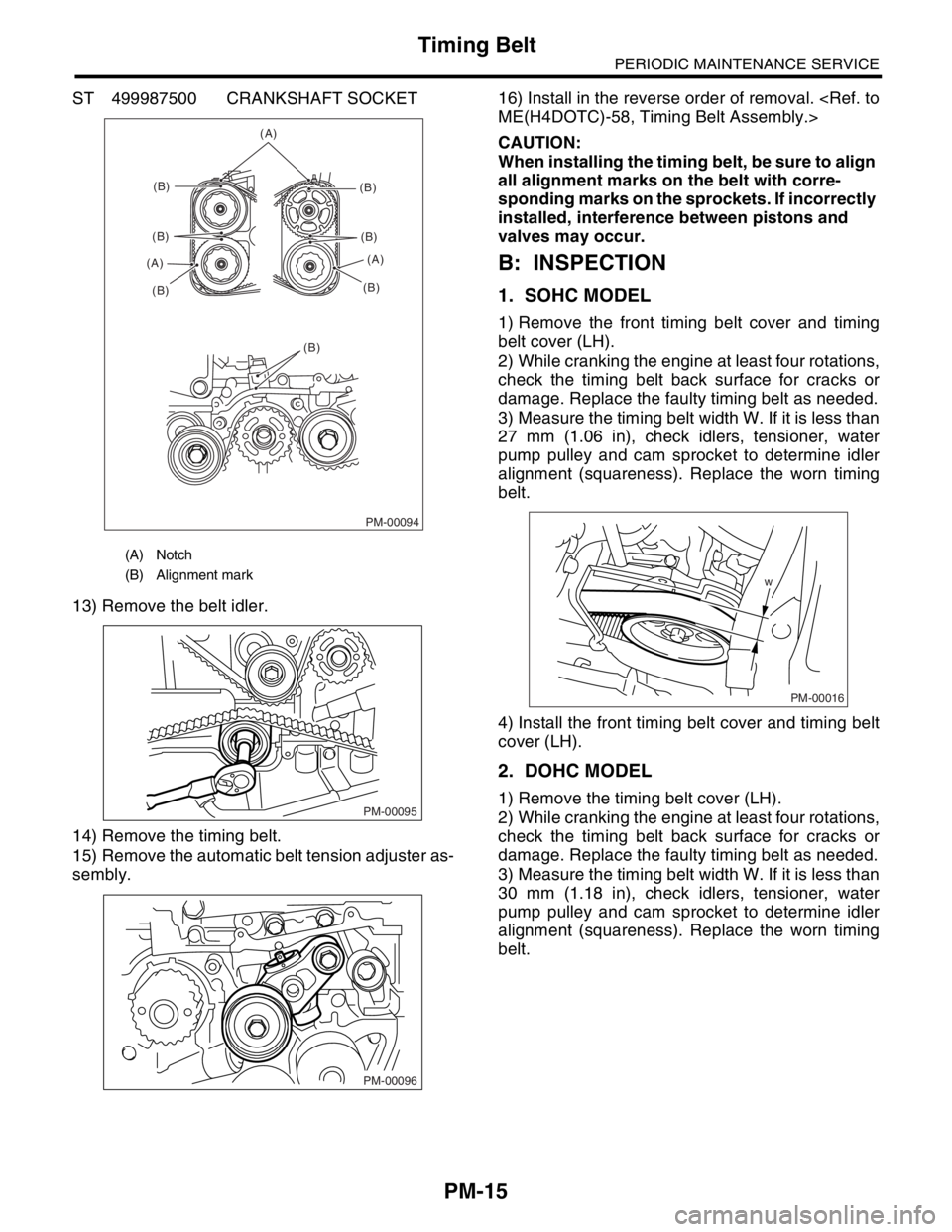
ST 499987500 CRANKSHAFT SOCKET
13) Remove the belt idler.
14) Remove the timing belt.
15) Remove the automatic belt tension adjuster as-
sembly.16) Install in the reverse order of removal.
CAUTION:
When installing the timing belt, be sure to align
all alignment marks on the belt with corre-
sponding marks on the sprockets. If incorrectly
installed, interference between pistons and
valves may occur.
B: INSPECTION
1. SOHC MODEL
1) Remove the front timing belt cover and timing
belt cover (LH).
2) While cranking the engine at least four rotations,
check the timing belt back surface for cracks or
damage. Replace the faulty timing belt as needed.
3) Measure the timing belt width W. If it is less than
27 mm (1.06 in), check idlers, tensioner, water
pump pulley and cam sprocket to determine idler
alignment (squareness). Replace the worn timing
belt.
4) Install the front timing belt cover and timing belt
cover (LH).
2. DOHC MODEL
1) Remove the timing belt cover (LH).
2) While cranking the engine at least four rotations,
check the timing belt back surface for cracks or
damage. Replace the faulty timing belt as needed.
3) Measure the timing belt width W. If it is less than
30 mm (1.18 in), check idlers, tensioner, water
pump pulley and cam sprocket to determine idler
alignment (squareness). Replace the worn timing
belt.
(A) Notch
(B) Alignment mark
PM-00094
(A)
(B)
(B)
(B) (A)(B)
(B)
(B)(A)
(B)
PM-00095
PM-00096
w
PM-00016
Page 801 of 2870
FU(H4SO)-19
FUEL INJECTION (FUEL SYSTEM)
Intake Manifold
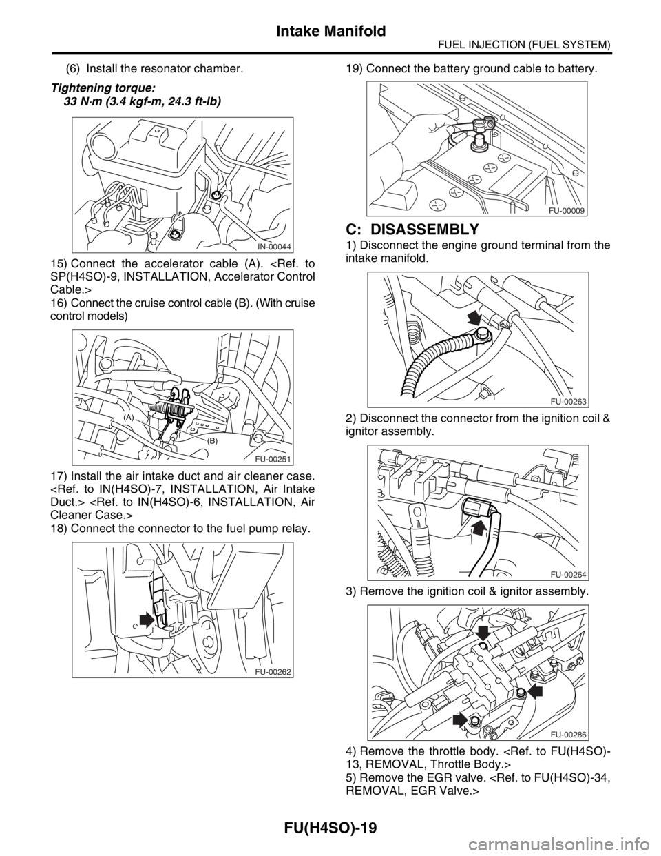
(6) Install the resonator chamber.
Tightening torque:
33 N
⋅m (3.4 kgf-m, 24.3 ft-lb)
15) Connect the accelerator cable (A).
Cable.>
16) Connect the cruise control cable (B). (With cruise
control models)
17) Install the air intake duct and air cleaner case.
18) Connect the connector to the fuel pump relay.19) Connect the battery ground cable to battery.
C: DISASSEMBLY
1) Disconnect the engine ground terminal from the
intake manifold.
2) Disconnect the connector from the ignition coil &
ignitor assembly.
3) Remove the ignition coil & ignitor assembly.
4) Remove the throttle body.
5) Remove the EGR valve.
FU-00251
(B)
(A)
FU-00262
FU-00009
FU-00263
FU-00264
FU-00286
Page 805 of 2870
FU(H4SO)-23
FUEL INJECTION (FUEL SYSTEM)
Intake Manifold
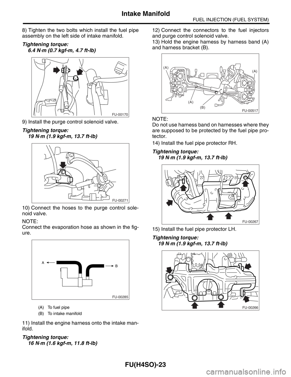
8) Tighten the two bolts which install the fuel pipe
assembly on the left side of intake manifold.
Tightening torque:
6.4 N
⋅m (0.7 kgf-m, 4.7 ft-lb)
9) Install the purge control solenoid valve.
Tightening torque:
19 N
⋅m (1.9 kgf-m, 13.7 ft-lb)
10) Connect the hoses to the purge control sole-
noid valve.
NOTE:
Connect the evaporation hose as shown in the fig-
ure.
11) Install the engine harness onto the intake man-
ifold.
Tightening torque:
16 N
⋅m (1.6 kgf-m, 11.8 ft-lb)12) Connect the connectors to the fuel injectors
and purge control solenoid valve.
13) Hold the engine harness by harness band (A)
and harness bracket (B).
NOTE:
Do not use harness band on harnesses where they
are supposed to be protected by the fuel pipe pro-
tector.
14) Install the fuel pipe protector RH.
Tightening torque:
19 N
⋅m (1.9 kgf-m, 13.7 ft-lb)
15) Install the fuel pipe protector LH.
Tightening torque:
19 N
⋅m (1.9 kgf-m, 13.7 ft-lb)
(A) To fuel pipe
(B) To intake manifold
FU-00170
FU-00271
FU-00285
A
B
FU-00517(B)(A)
(A)
(A)
FU-00267
FU-00266