Page 905 of 2870
ME(H4SO)-36
MECHANICAL
Engine Assembly
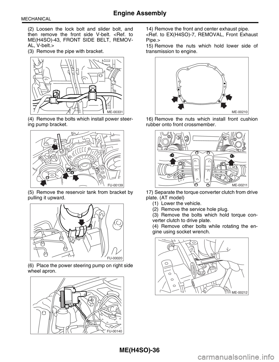
(2) Loosen the lock bolt and slider bolt, and
then remove the front side V-belt.
ME(H4SO)-43, FRONT SIDE BELT, REMOV-
AL, V-belt.>
(3) Remove the pipe with bracket.
(4) Remove the bolts which install power steer-
ing pump bracket.
(5) Remove the reservoir tank from bracket by
pulling it upward.
(6) Place the power steering pump on right side
wheel apron.14) Remove the front and center exhaust pipe.
Pipe.>
15) Remove the nuts which hold lower side of
transmission to engine.
16) Remove the nuts which install front cushion
rubber onto front crossmember.
17) Separate the torque converter clutch from drive
plate. (AT model)
(1) Lower the vehicle.
(2) Remove the service hole plug.
(3) Remove the bolts which hold torque con-
verter clutch to drive plate.
(4) Remove other bolts while rotating the en-
gine using socket wrench.
ME-00331
FU-00139
FU-00020
FU-00140ME-00210
ME-00211
ME-00212
Page 906 of 2870
ME(H4SO)-37
MECHANICAL
Engine Assembly
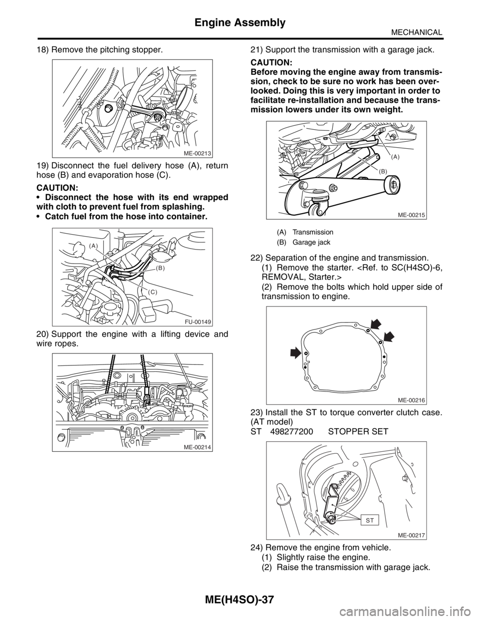
18) Remove the pitching stopper.
19) Disconnect the fuel delivery hose (A), return
hose (B) and evaporation hose (C).
CAUTION:
Disconnect the hose with its end wrapped
with cloth to prevent fuel from splashing.
Catch fuel from the hose into container.
20) Support the engine with a lifting device and
wire ropes.21) Support the transmission with a garage jack.
CAUTION:
Before moving the engine away from transmis-
sion, check to be sure no work has been over-
looked. Doing this is very important in order to
facilitate re-installation and because the trans-
mission lowers under its own weight.
22) Separation of the engine and transmission.
(1) Remove the starter.
REMOVAL, Starter.>
(2) Remove the bolts which hold upper side of
transmission to engine.
23) Install the ST to torque converter clutch case.
(AT model)
ST 498277200 STOPPER SET
24) Remove the engine from vehicle.
(1) Slightly raise the engine.
(2) Raise the transmission with garage jack.
ME-00213
FU-00149
(A)
(B)
(C)
ME-00214
(A) Transmission
(B) Garage jack
ME-00215
(B)(A)
ME-00216
ST
ME-00217
Page 907 of 2870
ME(H4SO)-38
MECHANICAL
Engine Assembly
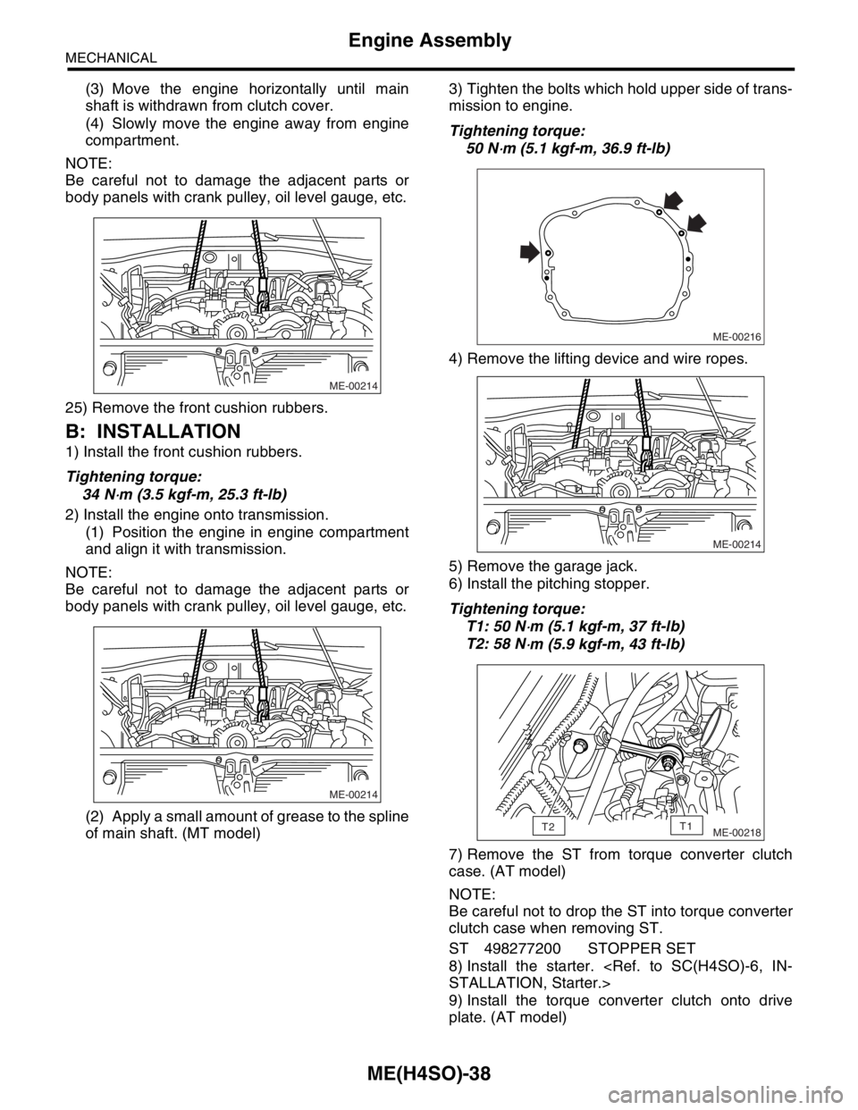
(3) Move the engine horizontally until main
shaft is withdrawn from clutch cover.
(4) Slowly move the engine away from engine
compartment.
NOTE:
Be careful not to damage the adjacent parts or
body panels with crank pulley, oil level gauge, etc.
25) Remove the front cushion rubbers.
B: INSTALLATION
1) Install the front cushion rubbers.
Tightening torque:
34 N
⋅m (3.5 kgf-m, 25.3 ft-lb)
2) Install the engine onto transmission.
(1) Position the engine in engine compartment
and align it with transmission.
NOTE:
Be careful not to damage the adjacent parts or
body panels with crank pulley, oil level gauge, etc.
(2) Apply a small amount of grease to the spline
of main shaft. (MT model)3) Tighten the bolts which hold upper side of trans-
mission to engine.
Tightening torque:
50 N
⋅m (5.1 kgf-m, 36.9 ft-lb)
4) Remove the lifting device and wire ropes.
5) Remove the garage jack.
6) Install the pitching stopper.
Tightening torque:
T1: 50 N
⋅m (5.1 kgf-m, 37 ft-lb)
T2: 58 N
⋅m (5.9 kgf-m, 43 ft-lb)
7) Remove the ST from torque converter clutch
case. (AT model)
NOTE:
Be careful not to drop the ST into torque converter
clutch case when removing ST.
ST 498277200 STOPPER SET
8) Install the starter.
STALLATION, Starter.>
9) Install the torque converter clutch onto drive
plate. (AT model)
ME-00214
ME-00214
ME-00216
ME-00214
ME-00218T2T1
Page 908 of 2870
ME(H4SO)-39
MECHANICAL
Engine Assembly
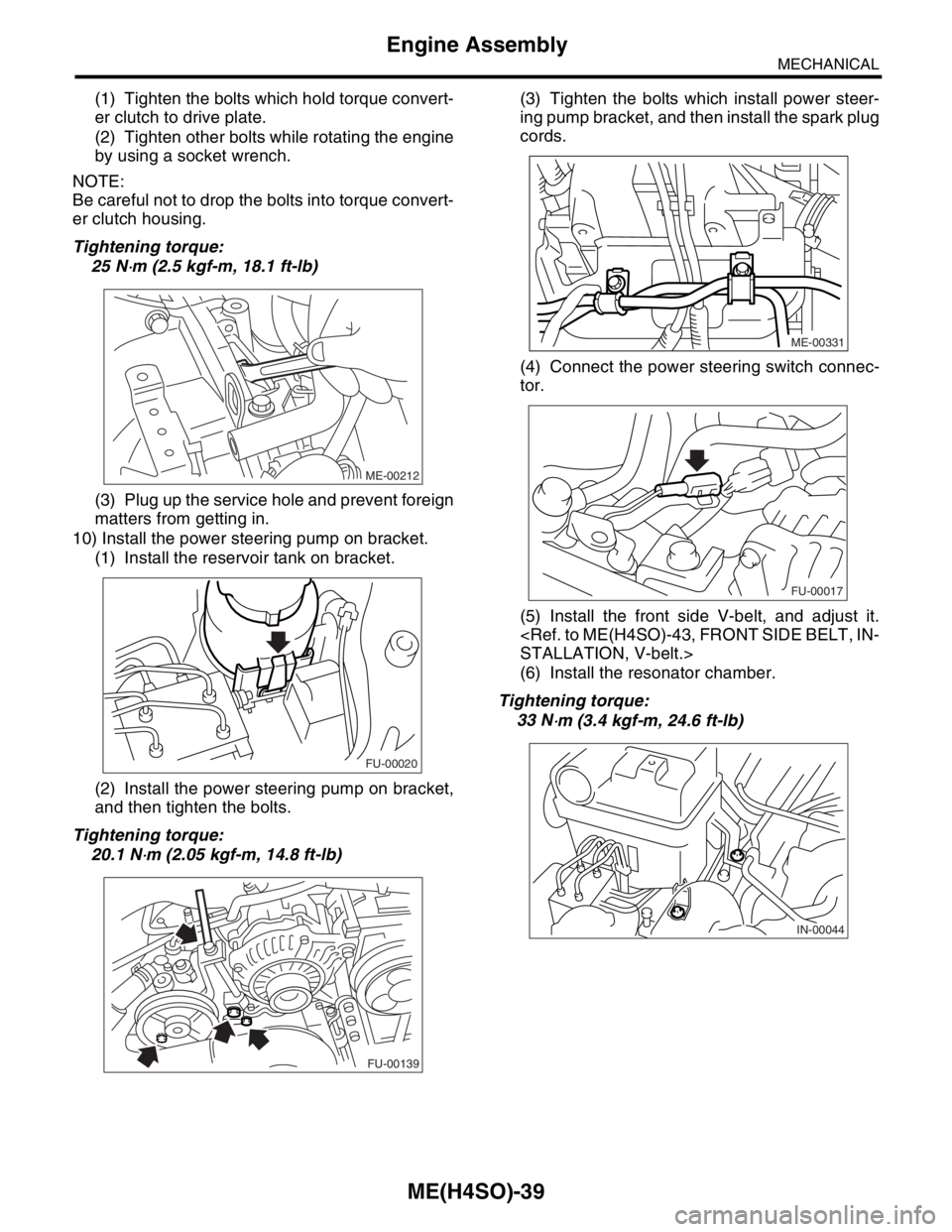
(1) Tighten the bolts which hold torque convert-
er clutch to drive plate.
(2) Tighten other bolts while rotating the engine
by using a socket wrench.
NOTE:
Be careful not to drop the bolts into torque convert-
er clutch housing.
Tightening torque:
25 N
⋅m (2.5 kgf-m, 18.1 ft-lb)
(3) Plug up the service hole and prevent foreign
matters from getting in.
10) Install the power steering pump on bracket.
(1) Install the reservoir tank on bracket.
(2) Install the power steering pump on bracket,
and then tighten the bolts.
Tightening torque:
20.1 N
⋅m (2.05 kgf-m, 14.8 ft-lb)(3) Tighten the bolts which install power steer-
ing pump bracket, and then install the spark plug
cords.
(4) Connect the power steering switch connec-
tor.
(5) Install the front side V-belt, and adjust it.
STALLATION, V-belt.>
(6) Install the resonator chamber.
Tightening torque:
33 N
⋅m (3.4 kgf-m, 24.6 ft-lb)
ME-00212
FU-00020
FU-00139
ME-00331
FU-00017
IN-00044
Page 909 of 2870
ME(H4SO)-40
MECHANICAL
Engine Assembly
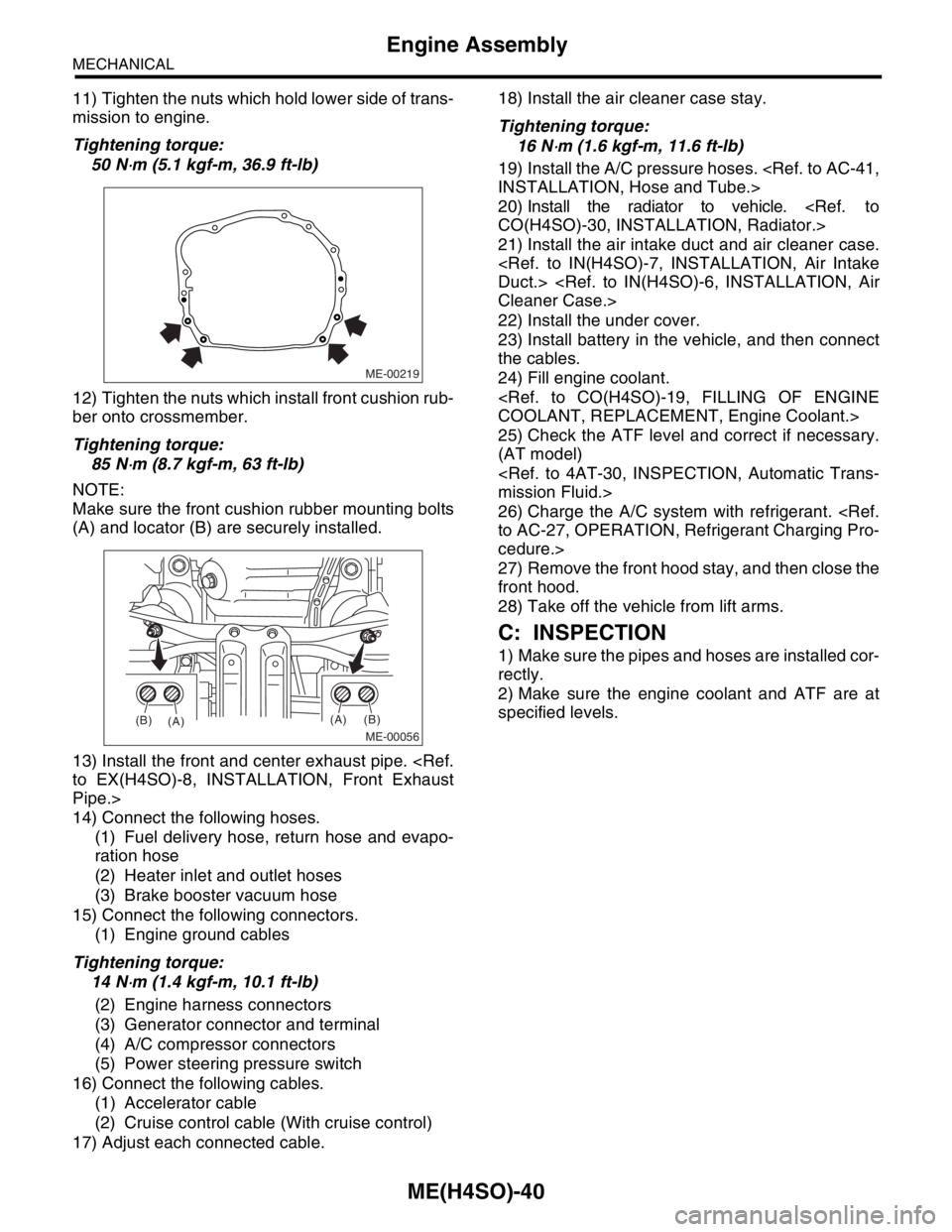
11) Tighten the nuts which hold lower side of trans-
mission to engine.
Tightening torque:
50 N
⋅m (5.1 kgf-m, 36.9 ft-lb)
12) Tighten the nuts which install front cushion rub-
ber onto crossmember.
Tightening torque:
85 N
⋅m (8.7 kgf-m, 63 ft-lb)
NOTE:
Make sure the front cushion rubber mounting bolts
(A) and locator (B) are securely installed.
13) Install the front and center exhaust pipe.
to EX(H4SO)-8, INSTALLATION, Front Exhaust
Pipe.>
14) Connect the following hoses.
(1) Fuel delivery hose, return hose and evapo-
ration hose
(2) Heater inlet and outlet hoses
(3) Brake booster vacuum hose
15) Connect the following connectors.
(1) Engine ground cables
Tightening torque:
14 N
⋅m (1.4 kgf-m, 10.1 ft-lb)
(2) Engine harness connectors
(3) Generator connector and terminal
(4) A/C compressor connectors
(5) Power steering pressure switch
16) Connect the following cables.
(1) Accelerator cable
(2) Cruise control cable (With cruise control)
17) Adjust each connected cable.18) Install the air cleaner case stay.
Tightening torque:
16 N
⋅m (1.6 kgf-m, 11.6 ft-lb)
19) Install the A/C pressure hoses.
INSTALLATION, Hose and Tube.>
20) Install the radiator to vehicle.
CO(H4SO)-30, INSTALLATION, Radiator.>
21) Install the air intake duct and air cleaner case.
Duct.>
Cleaner Case.>
22) Install the under cover.
23) Install battery in the vehicle, and then connect
the cables.
24) Fill engine coolant.
COOLANT, REPLACEMENT, Engine Coolant.>
25) Check the ATF level and correct if necessary.
(AT model)
mission Fluid.>
26) Charge the A/C system with refrigerant.
to AC-27, OPERATION, Refrigerant Charging Pro-
cedure.>
27) Remove the front hood stay, and then close the
front hood.
28) Take off the vehicle from lift arms.
C: INSPECTION
1) Make sure the pipes and hoses are installed cor-
rectly.
2) Make sure the engine coolant and ATF are at
specified levels.
ME-00219
ME-00056
(A)
(A)(B)
(B)
Page 910 of 2870
ME(H4SO)-41
MECHANICAL
Engine Mounting
10.Engine Mounting
A: REMOVAL
1) Remove the engine assembly.
ME(H4SO)-34, REMOVAL, Engine Assembly.>
2) Remove the engine mounting from engine as-
sembly.
B: INSTALLATION
Install in the reverse order of removal.
Tightening torque:
Engine mounting:
34 N
⋅m (3.5 kgf-m, 25.3 ft-lb)
C: INSPECTION
Make sure there are no cracks or other damage.
Page 923 of 2870

MECHANICAL
ME(H4SO)
Page
1. General Description ....................................................................................2
2. Compression .............................................................................................25
3. Idle Speed .................................................................................................26
4. Ignition Timing ...........................................................................................27
5. Intake Manifold Vacuum............................................................................28
6. Engine Oil Pressure ..................................................................................29
7. Fuel Pressure ............................................................................................30
8. Valve Clearance ........................................................................................31
9. Engine Assembly ......................................................................................34
10. Engine Mounting .......................................................................................41
11. Preparation for Overhaul ...........................................................................42
12. V-belt .........................................................................................................43
13. Crank Pulley ..............................................................................................45
14. Timing Belt Cover......................................................................................47
15. Timing Belt ................................................................................................48
16. Cam Sprocket ...........................................................................................53
17. Crank Sprocket .........................................................................................55
18. Valve Rocker Assembly ............................................................................56
19. Camshaft ...................................................................................................58
20. Cylinder Head ...........................................................................................62
21. Cylinder Block ...........................................................................................69
22. Engine Trouble in General ........................................................................91
23. Engine Noise .............................................................................................96
Page 930 of 2870
ME(H4SO)-59
MECHANICAL
Camshaft
16) Remove the plug from rear side of camshaft.
CAUTION:
Do not remove the oil seal unless necessary.
Do not scratch the journal surface when re-
moving oil seal.
B: INSTALLATION
1) Apply a coat of engine oil to the camshaft jour-
nals, and then install the camshaft.
2) Install the camshaft cap.
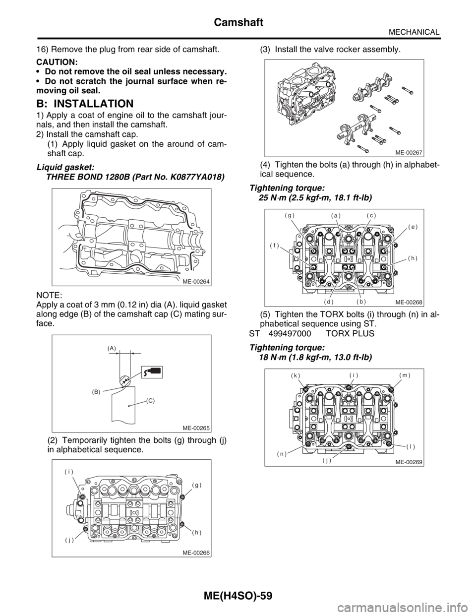
(1) Apply liquid gasket on the around of cam-
shaft cap.
Liquid gasket:
THREE BOND 1280B (Part No. K0877YA018)
NOTE:
Apply a coat of 3 mm (0.12 in) dia (A). liquid gasket
along edge (B) of the camshaft cap (C) mating sur-
face.
(2) Temporarily tighten the bolts (g) through (j)
in alphabetical sequence.(3) Install the valve rocker assembly.
(4) Tighten the bolts (a) through (h) in alphabet-
ical sequence.
Tightening torque:
25 N
⋅m (2.5 kgf-m, 18.1 ft-lb)
(5) Tighten the TORX bolts (i) through (n) in al-
phabetical sequence using ST.
ST 499497000 TORX PLUS
Tightening torque:
18 N
⋅m (1.8 kgf-m, 13.0 ft-lb)
ME-00264
ME-00265
(A)
(B)
(C)
ME-00266
(g)
(h)
(j) (i)
ME-00267
ME-00268
(a)
(b)(c)
(d)(e)
(f)(g)
(h)
ME-00269
(i)
(j)(m)
(n)(k)
(l)