2004 SUBARU FORESTER battery replacement
[x] Cancel search: battery replacementPage 39 of 2870
AC-37
HVAC SYSTEM (HEATER, VENTILATOR AND A/C)
Condenser
12.Condenser
A: REMOVAL
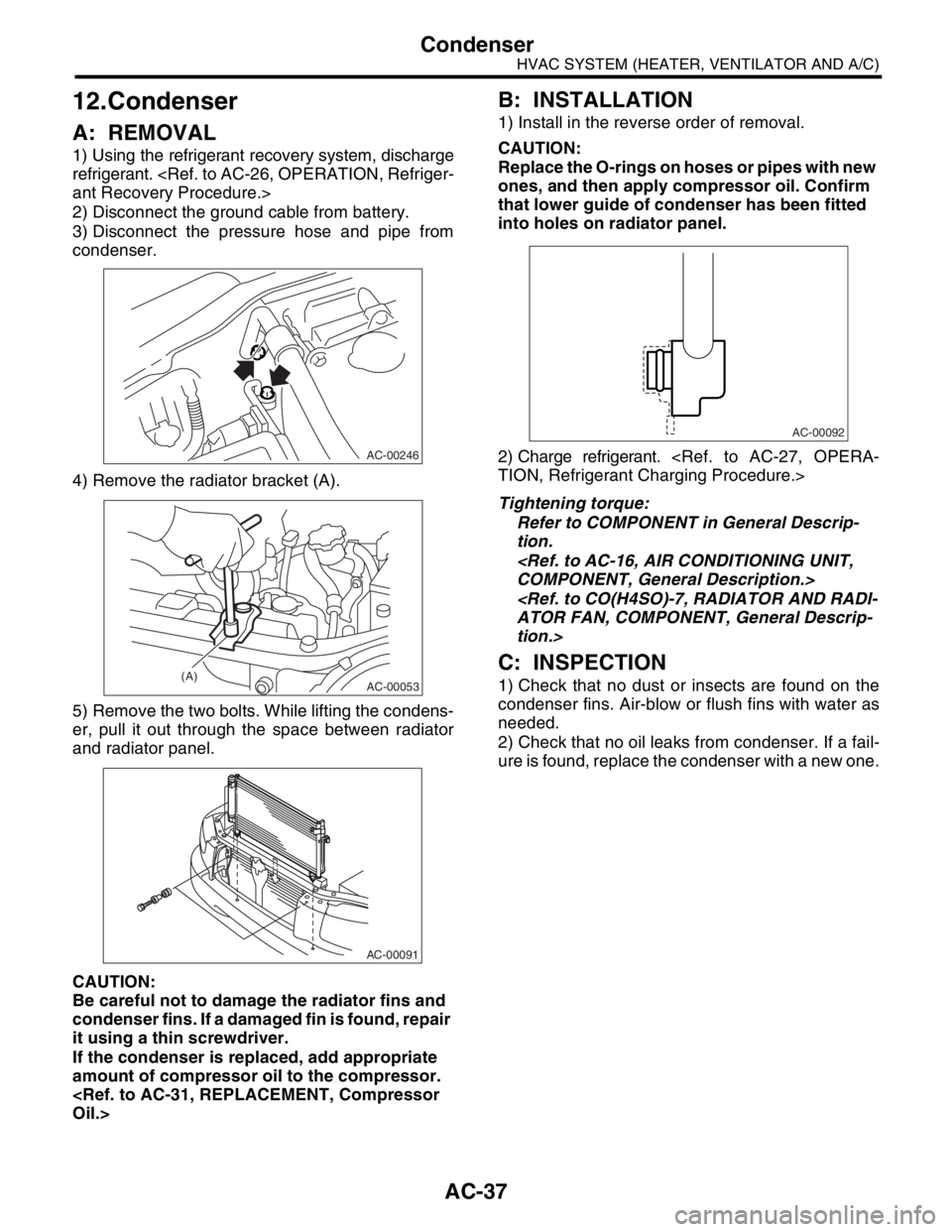
1) Using the refrigerant recovery system, discharge
refrigerant.
2) Disconnect the ground cable from battery.
3) Disconnect the pressure hose and pipe from
condenser.
4) Remove the radiator bracket (A).
5) Remove the two bolts. While lifting the condens-
er, pull it out through the space between radiator
and radiator panel.
CAUTION:
Be careful not to damage the radiator fins and
condenser fins. If a damaged fin is found, repair
it using a thin screwdriver.
If the condenser is replaced, add appropriate
amount of compressor oil to the compressor.
B: INSTALLATION
1) Install in the reverse order of removal.
CAUTION:
Replace the O-rings on hoses or pipes with new
ones, and then apply compressor oil. Confirm
that lower guide of condenser has been fitted
into holes on radiator panel.
2) Charge refrigerant.
Tightening torque:
Refer to COMPONENT in General Descrip-
tion.
tion.>
C: INSPECTION
1) Check that no dust or insects are found on the
condenser fins. Air-blow or flush fins with water as
needed.
2) Check that no oil leaks from condenser. If a fail-
ure is found, replace the condenser with a new one.
AC-00246
AC-00053(A)
AC-00091
AC-00092
Page 51 of 2870
AC-49
HVAC SYSTEM (HEATER, VENTILATOR AND A/C)
Heater Cock Solenoid Valve
24.Heater Cock Solenoid Valve
A: REMOVAL
1) Drain the engine coolant.
2) Remove the battery.
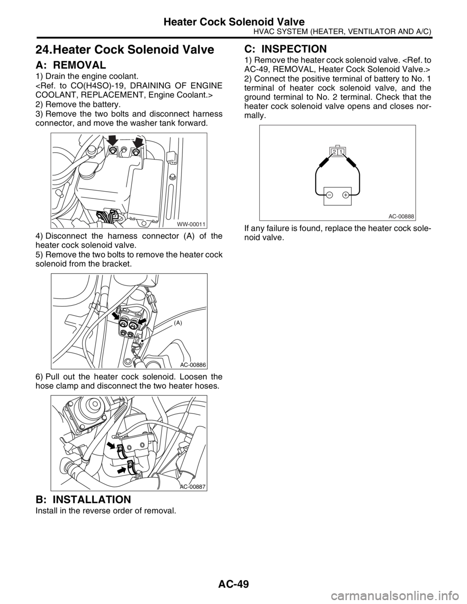
3) Remove the two bolts and disconnect harness
connector, and move the washer tank forward.
4) Disconnect the harness connector (A) of the
heater cock solenoid valve.
5) Remove the two bolts to remove the heater cock
solenoid from the bracket.
6) Pull out the heater cock solenoid. Loosen the
hose clamp and disconnect the two heater hoses.
B: INSTALLATION
Install in the reverse order of removal.
C: INSPECTION
1) Remove the heater cock solenoid valve.
2) Connect the positive terminal of battery to No. 1
terminal of heater cock solenoid valve, and the
ground terminal to No. 2 terminal. Check that the
heater cock solenoid valve opens and closes nor-
mally.
If any failure is found, replace the heater cock sole-
noid valve.
WW-00011
AC-00886
(A)
AC-00887
1 2
AC-00888
Page 455 of 2870
SL-35
SECURITY AND LOCK
Ignition Key Lock
17.Ignition Key Lock
A: REPLACEMENT
1) Remove the ground cable from battery.
2) Remove the steering column.
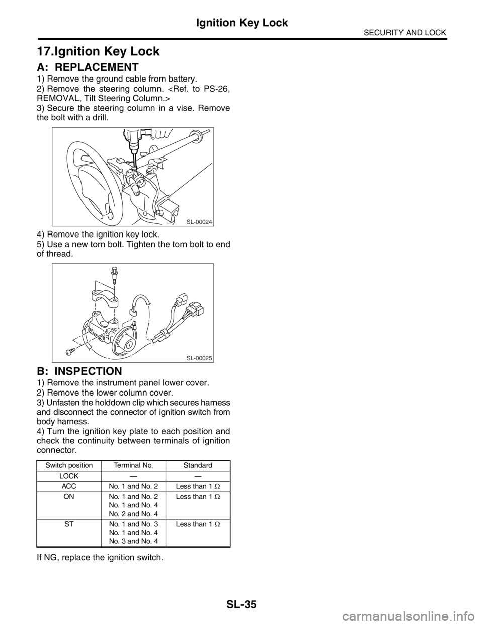
3) Secure the steering column in a vise. Remove
the bolt with a drill.
4) Remove the ignition key lock.
5) Use a new torn bolt. Tighten the torn bolt to end
of thread.
B: INSPECTION
1) Remove the instrument panel lower cover.
2) Remove the lower column cover.
3) Unfasten the holddown clip which secures harness
and disconnect the connector of ignition switch from
body harness.
4) Turn the ignition key plate to each position and
check the continuity between terminals of ignition
connector.
If NG, replace the ignition switch.
Switch position Terminal No. Standard
LOCK — —
ACC No. 1 and No. 2 Less than 1 Ω
ON No. 1 and No. 2
No. 1 and No. 4
No. 2 and No. 4Less than 1 Ω
ST No. 1 and No. 3
No. 1 and No. 4
No. 3 and No. 4Less than 1 Ω
SL-00024
SL-00025
Page 461 of 2870
SL-41
SECURITY AND LOCK
Keyless Transmitter
23.Keyless Transmitter
A: REMOVAL
1. TRANSMITTER BATTERY
Remove the battery from transmitter.
NOTE:
To prevent static electricity damage to transmitter
printed circuit board, touch the steel area of building
with hand to discharge the static electricity carried
on body or clothes before disassembling transmitter.
B: INSTALLATION
1. TRANSMITTER BATTERY
Install in the reverse order of removal.
C: INSPECTION
1. TRANSMITTER BATTERY
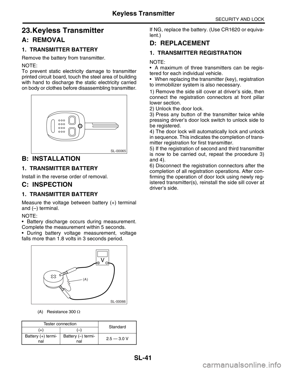
Measure the voltage between battery (+) terminal
and (–) terminal.
NOTE:
Battery discharge occurs during measurement.
Complete the measurement within 5 seconds.
During battery voltage measurement, voltage
falls more than 1.8 volts in 3 seconds period.If NG, replace the battery. (Use CR1620 or equiva-
lent.)
D: REPLACEMENT
1. TRANSMITTER REGISTRATION
NOTE:
A maximum of three transmitters can be regis-
tered for each individual vehicle.
When replacing the transmitter (key), registration
to immobilizer system is also necessary.
1) Remove the side sill cover at driver’s side, then
connect the registration connectors at front pillar
lower section.
2) Unlock the door lock.
3) Press any button of the transmitter twice while
pressing driver’s door lock switch to unlock side to
be registered.
4) The door lock will automatically lock and unlock
in sequence. This indicates the completion of trans-
mitter registration for first transmitter.
5) If the registration of second and third transmitter
is now to be carried out, repeat the procedure 3)
and 4).
6) Disconnect the registration connectors after the
completion of all registration operations. After con-
firming the operation of door lock using newly reg-
istered transmitter(s), reinstall the side sill cover at
driver’s side.
(A) Resistance 300 Ω
Tester connection
Standard
(+) (–)
Battery (+) termi-
nalBattery (–) termi-
nal2.5 — 3.0 V
SL-00065
SL-00066
(A)
Page 794 of 2870
FU(H4SO)-12
FUEL INJECTION (FUEL SYSTEM)
General Description
C: CAUTION
Wear working clothing, including a cap, protec-
tive goggles, and protective shoes during opera-
tion.
Remove contamination including dirt and corro-
sion before removal, installation or disassembly.
Keep the disassembled parts in order and pro-
tect them from dust or dirt.
Before removal, installation or disassembly, be
sure to clarify the failure. Avoid unnecessary re-
moval, installation, disassembly, and replacement. Be careful not to burn yourself, because each
part on the vehicle is hot after running.
Be sure to tighten fasteners including bolts and
nuts to the specified torque.
Place shop jacks or rigid racks at the specified
points.
Before disconnecting electrical connectors of
sensors or units, be sure to disconnect negative
terminal from battery.
Place “NO FIRE” signs near the working area.
Be careful not to spill fuel on the floor.
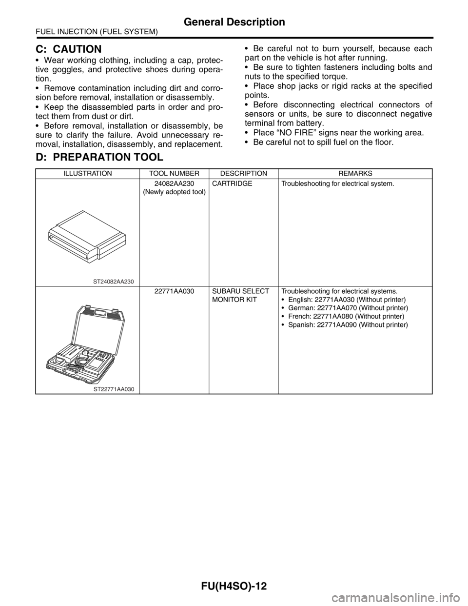
D: PREPARATION TOOL
ILLUSTRATION TOOL NUMBER DESCRIPTION REMARKS
24082AA230
(Newly adopted tool)CARTRIDGE Troubleshooting for electrical system.
22771AA030 SUBARU SELECT
MONITOR KITTroubleshooting for electrical systems.
English: 22771AA030 (Without printer)
German: 22771AA070 (Without printer)
French: 22771AA080 (Without printer)
Spanish: 22771AA090 (Without printer)
ST24082AA230
ST22771AA030
Page 851 of 2870

EC(H4SO)-2
EMISSION CONTROL (AUX. EMISSION CONTROL DEVICE)
General Description
1. General Description
A: CAUTION
Wear working clothing, including a cap, protec-
tive goggles, and protective shoes during opera-
tion.
Remove contamination including dirt and corro-
sion before removal, installation or disassembly.
Keep the disassembled parts in order and pro-
tect them from dust or dirt.
Before removal, installation or disassembly, be
sure to clarify the failure. Avoid unnecessary re-
moval, installation, disassembly, and replacement.
Be careful not to burn yourself, because each
part on the vehicle is hot after running.
Be sure to tighten fasteners including bolts and
nuts to the specified torque.
Place shop jacks or rigid racks at the specified
points.
Before disconnecting electrical connectors of
sensors or units, be sure to disconnect the ground
cable from battery.
Page 864 of 2870

IN(H4SO)-4
INTAKE (INDUCTION)
General Description
B: CAUTION
Wear working clothing, including a cap, protec-
tive goggles, and protective shoes during opera-
tion.
Remove contamination including dirt and corro-
sion before removal, installation or disassembly.
Keep the disassembled parts in order and pro-
tect them from dust or dirt.
Before removal, installation or disassembly, be
sure to clarify the failure. Avoid unnecessary re-
moval, installation, disassembly, and replacement.
Be careful not to burn your hands, because each
part on the vehicle is hot after running.
Be sure to tighten fasteners including bolts and
nuts to the specified torque.
Place shop jacks or rigid racks at the specified
points.
Before disconnecting electrical connectors of
sensor or units, be sure to disconnect the ground
cable from battery.
Page 884 of 2870
ME(H4SO)-15
MECHANICAL
General Description
C: CAUTION
Wear working clothing, including a cap, protec-
tive goggles and protective shoes during operation.
Remove contamination including dirt and corro-
sion before removal, installation or disassembly.
Keep the disassembled parts in order and pro-
tect them from dust or dirt.
Before removal, installation or disassembly, be
sure to clarify the failure. Avoid unnecessary re-
moval, installation, disassembly and replacement.
Be careful not to burn yourself, because each
part in the vehicle is hot after running.
Be sure to tighten bolts and nuts to the specified
torque.
Place shop jacks or rigid racks at the specified
points.
Before disconnecting electrical connectors of
sensors or units, be sure to disconnect the ground
cable from battery.
All parts should be thoroughly cleaned, paying
special attention to the engine oil passages, pis-
tons and bearings. Rotating parts and sliding parts such as piston,
bearing and gear should be coated with oil prior to
assembly.
Be careful not to let oil, grease or coolant contact
the timing belt, clutch disc and flywheel.
All removed parts, if to be reused, should be re-
installed in the original positions and directions.
Bolts, nuts and washers should be replaced with
new ones as required.
Even if necessary inspections have been made
in advance, proceed with assembly work while
making rechecks.
Remove or install engine in an area where chain
hoists, lifting devices, etc. are available for ready
use.
Be sure not to damage coated surfaces of body
panels with tools, or not to stain seats and windows
with coolant or oil. Place a cover over fenders, as
required, for protection.
Prior to starting work, prepare the following:
Service tools, clean cloth, containers to catch cool-
ant and oil, wire ropes, chain hoist, transmission
jacks, etc.
Lift-up or lower the vehicle when necessary.
Make sure to support the correct positions.
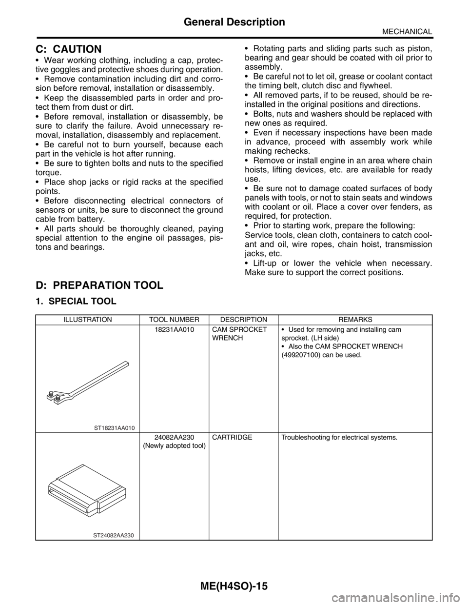
D: PREPARATION TOOL
1. SPECIAL TOOL
ILLUSTRATION TOOL NUMBER DESCRIPTION REMARKS
18231AA010 CAM SPROCKET
WRENCH Used for removing and installing cam
sprocket. (LH side)
Also the CAM SPROCKET WRENCH
(499207100) can be used.
24082AA230
(Newly adopted tool)CARTRIDGE Troubleshooting for electrical systems.
ST18231AA010
ST24082AA230