Page 783 of 2870

FUEL INJECTION (FUEL SYSTEM)
FU(H4SO)
Page
1. General Description ....................................................................................2
2. Throttle Body .............................................................................................13
3. Intake Manifold ..........................................................................................14
4. Engine Coolant Temperature Sensor........................................................25
5. Crankshaft Position Sensor.......................................................................26
6. Camshaft Position Sensor.........................................................................27
7. Knock Sensor ............................................................................................28
8. Throttle Position Sensor ............................................................................29
9. Manifold Absolute Pressure Sensor ..........................................................31
10. Intake Air Temperature Sensor .................................................................32
11. Idle Air Control Solenoid Valve .................................................................33
12. EGR Valve ................................................................................................34
13. Fuel Injector ..............................................................................................35
14. Front Oxygen (A/F) Sensor .......................................................................40
15. Rear Oxygen Sensor.................................................................................42
16. Engine Control Module (ECM) ..................................................................44
17. Main Relay ................................................................................................45
18. Fuel Pump Relay.......................................................................................46
19. Fuel ...........................................................................................................47
20. Fuel Tank ..................................................................................................48
21. Fuel Filler Pipe ..........................................................................................51
22. Fuel Pump .................................................................................................55
23. Fuel Level Sensor .....................................................................................57
24. Fuel Sub Level Sensor ..............................................................................58
25. Fuel Filter ..................................................................................................60
26. Fuel Cut Valve...........................................................................................61
27. Fuel Damper Valve ...................................................................................62
28. Fuel Delivery, Return and Evaporation Lines............................................63
29. Fuel System Trouble in General ...............................................................66
Page 786 of 2870
FU(H4SO)-4
FUEL INJECTION (FUEL SYSTEM)
General Description
(1) Intake manifold gasket RH (11) Intake manifold gasket LH (21) Accelerator cable bracket
(2) Fuel injector pipe (12) Fuel pipe protector LH (22) EGR valve
(3) Fuel injector (13) Plug cord holder LH (23) Gasket
(4) O-ring (14) Fuel pipe protector RH
(5) O-ring (15) Fuel pipe ASSYTightening torque: N
⋅m (kgf-m, ft-lb)
(6) Plug (16) Fuel hoseT1: 1.5 (0.15, 1.1)
(7) PCV valve (17) ClipT2: 6.4 (0.7, 4.7)
(8) Purge control solenoid valve (18) ClipT3: 17 (1.7, 12.5)
(9) Nipple (19) Guide pinT4: 19 (1.9, 13.7)
(10) Intake manifold (20) Plug cord holder RHT5: 25 (2.5, 18.1)
Page 802 of 2870
FU(H4SO)-20
FUEL INJECTION (FUEL SYSTEM)
Intake Manifold
6) Disconnect the pressure regulator vacuum hose
from the intake manifold.
7) Remove the fuel pipe protector LH.
8) Remove the fuel pipe protector RH.
9) Disconnect the connectors from the fuel injec-
tors.10) Disconnect the connector from the purge con-
trol solenoid valve.
11) Disconnect the air by-pass hose from the purge
control solenoid valve.
12) Remove the harness bands (A) and harness
bracket (B) which hold engine harness onto the in-
take manifold.
13) Remove the engine harness from the intake
manifold.
14) Remove the purge control solenoid valve.
15) Remove the bolt which installs injector pipe on
the intake manifold as shown in figure.
FU-00265
FU-00266
FU-00267
FU-00268
FU-00269
FU-00517(B)(A)
(A)
(A)
FU-00271
FU-00272
Page 803 of 2870

FU(H4SO)-21
FUEL INJECTION (FUEL SYSTEM)
Intake Manifold
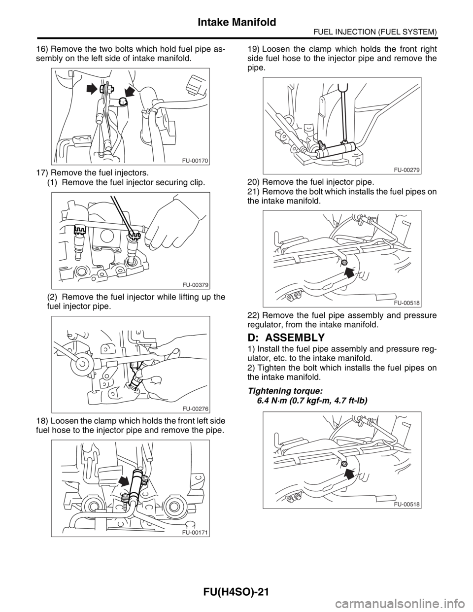
16) Remove the two bolts which hold fuel pipe as-
sembly on the left side of intake manifold.
17) Remove the fuel injectors.
(1) Remove the fuel injector securing clip.
(2) Remove the fuel injector while lifting up the
fuel injector pipe.
18) Loosen the clamp which holds the front left side
fuel hose to the injector pipe and remove the pipe.19) Loosen the clamp which holds the front right
side fuel hose to the injector pipe and remove the
pipe.
20) Remove the fuel injector pipe.
21) Remove the bolt which installs the fuel pipes on
the intake manifold.
22) Remove the fuel pipe assembly and pressure
regulator, from the intake manifold.
D: ASSEMBLY
1) Install the fuel pipe assembly and pressure reg-
ulator, etc. to the intake manifold.
2) Tighten the bolt which installs the fuel pipes on
the intake manifold.
Tightening torque:
6.4 N
⋅m (0.7 kgf-m, 4.7 ft-lb)
FU-00170
FU-00379
FU-00276
FU-00171
FU-00279
FU-00518
FU-00518
Page 804 of 2870
FU(H4SO)-22
FUEL INJECTION (FUEL SYSTEM)
Intake Manifold
3) Connect the right side fuel hose to the injector
pipe, and tighten the clamp screw.
4) Install the fuel injector pipe.
5) Connect the left side fuel hose to the injector
pipe, and tighten the clamp screw.
6) Install the fuel injectors.
NOTE:
Replace the O-rings with new ones.NOTE:
Do not forget to install the fuel injector securing clip.
7) Tighten the bolt which installs the injector pipe
on the intake manifold.
Tightening torque:
6.4 N
⋅m (0.7 kgf-m, 4.7 ft-lb)
Tightening torque:
19 N
⋅m (1.9 kgf-m, 13.7 ft-lb)
(A) O-ring
(B) Fuel injector
FU-00279
FU-00171
FU-02097
(A)
(A)(B)
FU-00379
FU-00283
FU-00284
Page 805 of 2870

FU(H4SO)-23
FUEL INJECTION (FUEL SYSTEM)
Intake Manifold
8) Tighten the two bolts which install the fuel pipe
assembly on the left side of intake manifold.
Tightening torque:
6.4 N
⋅m (0.7 kgf-m, 4.7 ft-lb)
9) Install the purge control solenoid valve.
Tightening torque:
19 N
⋅m (1.9 kgf-m, 13.7 ft-lb)
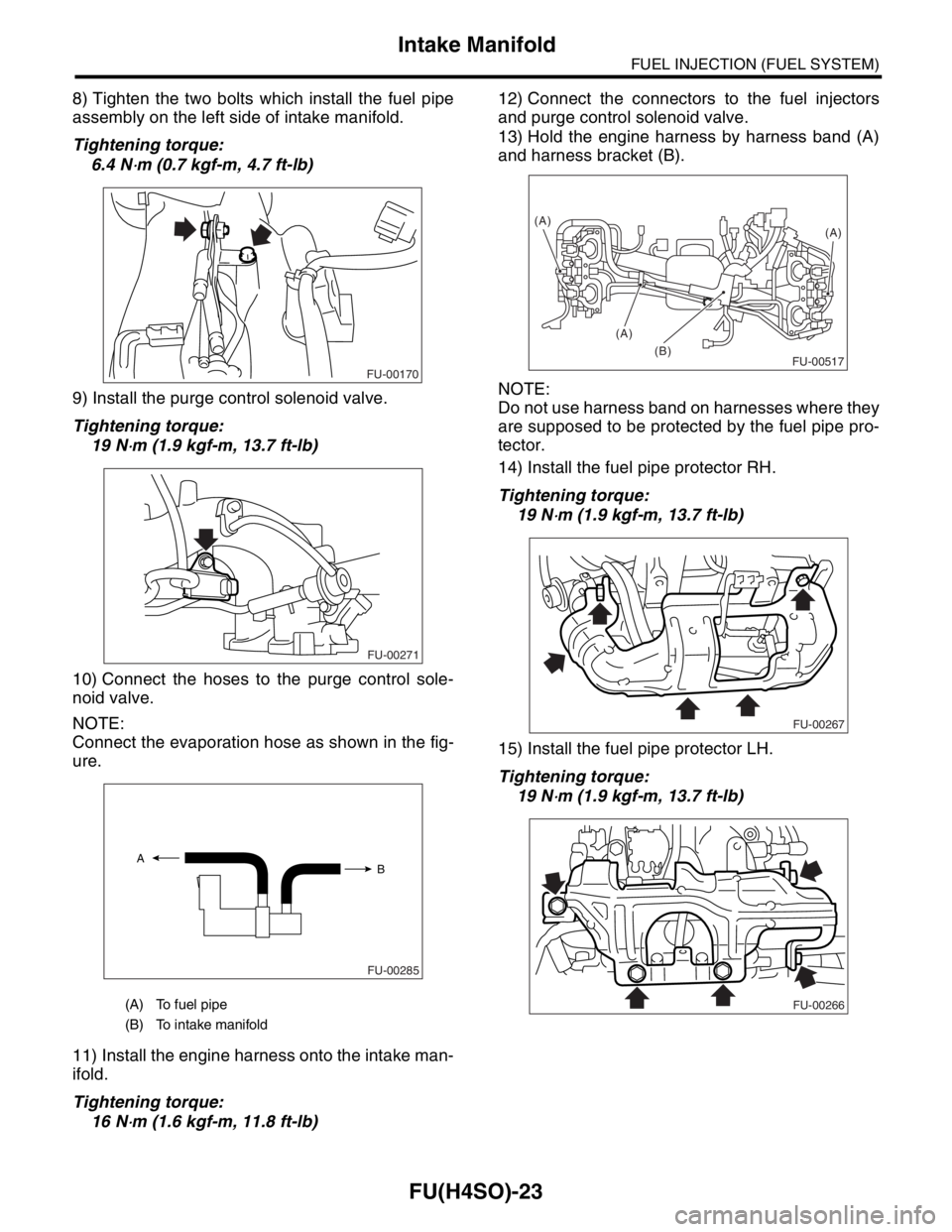
10) Connect the hoses to the purge control sole-
noid valve.
NOTE:
Connect the evaporation hose as shown in the fig-
ure.
11) Install the engine harness onto the intake man-
ifold.
Tightening torque:
16 N
⋅m (1.6 kgf-m, 11.8 ft-lb)12) Connect the connectors to the fuel injectors
and purge control solenoid valve.
13) Hold the engine harness by harness band (A)
and harness bracket (B).
NOTE:
Do not use harness band on harnesses where they
are supposed to be protected by the fuel pipe pro-
tector.
14) Install the fuel pipe protector RH.
Tightening torque:
19 N
⋅m (1.9 kgf-m, 13.7 ft-lb)
15) Install the fuel pipe protector LH.
Tightening torque:
19 N
⋅m (1.9 kgf-m, 13.7 ft-lb)
(A) To fuel pipe
(B) To intake manifold
FU-00170
FU-00271
FU-00285
A
B
FU-00517(B)(A)
(A)
(A)
FU-00267
FU-00266
Page 817 of 2870
FU(H4SO)-35
FUEL INJECTION (FUEL SYSTEM)
Fuel Injector
13.Fuel Injector
A: REMOVAL
1. RH SIDE
1) Release the fuel pressure.
PRESSURE, OPERATION, Fuel.>
2) Open the fuel flap lid, and remove the fuel filler
cap.
3) Disconnect the ground cable from battery.
4) Remove the resonator chamber.
IN(H4SO)-8, REMOVAL, Resonator Chamber.>
5) Remove the spark plug cords from the spark
plugs (#1 and #3 cylinders).6) Remove the power steering pump and reservoir
tank from the brackets.
(1) Remove the front side V-belt.
ME(H4SO)-43, REMOVAL, V-belt.>
(2) Remove the bolts which hold the power
steering pipes onto the intake manifold protec-
tor.
(3) Remove the bolts which install the power
steering pump to the bracket.
(4) Disconnect the connector from the power
steering pump switch.
FU-00009
FU-00302
FU-00255
FU-00139
FU-00017
Page 818 of 2870
FU(H4SO)-36
FUEL INJECTION (FUEL SYSTEM)
Fuel Injector
(5) Remove the power steering tank from the
bracket by pulling it upwards.
(6) Place the power steering pump and reser-
voir tank on the right side wheel apron.
7) Remove the fuel pipe protector RH.
8) Disconnect the connector from fuel injector.9) Remove the bolts which holds the fuel injector
pipe to the intake manifold.
10) Remove the fuel injector from the intake mani-
fold.
(1) Remove the fuel injector securing clip.
(2) Remove the fuel injector while lifting up the
fuel injector pipe.
FU-00020
FU-00021
FU-00267
FU-00303
FU-00284
FU-00304
FU-00305
FU-00306